Language selection

Search

Patent 2721468 Summary

Third-party information liability

Some of the information on this Web page has been provided by external sources. The Government of Canada is not responsible for the accuracy, reliability or currency of the information supplied by external sources. Users wishing to rely upon this information should consult directly with the source of the information. Content provided by external sources is not subject to official languages, privacy and accessibility requirements.

Claims and Abstract availability

Any discrepancies in the text and image of the Claims and Abstract are due to differing posting times. Text of the Claims and Abstract are posted:

  • At the time the application is open to public inspection;
  • At the time of issue of the patent (grant).
(12) Patent: (11) CA 2721468
(54) English Title: DUAL DIRECTIONAL DOWNHOLE OVERPRESSURE VALVE
(54) French Title: SOUPAPE DE SURPRESSION BIDIRECTIONNELLE DE FOND DE TROU
Status: Expired and beyond the Period of Reversal
Bibliographic Data
(51) International Patent Classification (IPC):
  • E21B 34/06 (2006.01)
  • E21B 33/13 (2006.01)
  • E21B 33/14 (2006.01)
(72) Inventors :
  • EVERTSEN, STEFFEN (Norway)
  • EVERTSEN, OLAV (Norway)
(73) Owners :
  • WELLTEC A/S
(71) Applicants :
  • HPI TECHNOLOGY AS (Norway)
(74) Agent: GOWLING WLG (CANADA) LLP
(74) Associate agent:
(45) Issued: 2015-06-23
(86) PCT Filing Date: 2008-01-07
(87) Open to Public Inspection: 2009-07-17
Examination requested: 2012-11-21
Availability of licence: N/A
Dedicated to the Public: N/A
(25) Language of filing: English

Patent Cooperation Treaty (PCT): Yes
(86) PCT Filing Number: PCT/NO2008/000002
(87) International Publication Number: WO 2008085057
(85) National Entry: 2010-05-07

(30) Application Priority Data:
Application No. Country/Territory Date
20070060 (Norway) 2007-01-08

Abstracts

English Abstract


Dual directional downhole overpressure
valve (1) comprising a valve housing (2) and where a
first valve body (4) is forced with a first force against a
first valve seat (8), and where a second valve body (6)
is forced against a second valve seat (26) positioned in
the first valve body (4) with a force smaller than the
first force, the first force and the second force acting in
opposite directions.


French Abstract

L'invention concerne une soupape de surpression bidirectionnelle de fond de trou (1) qui comprend un boîtier de soupape (2), et dans laquelle un premier corps de soupape (4) est forcé avec une première force contre un premier siège de soupape (8) et un second corps de soupape (6) est forcé contre un second siège de soupape (26) positionné dans le premier corps de soupape (4) avec une force inférieure à la première force, la première force et la seconde force agissant dans des directions opposées.

Claims

Note: Claims are shown in the official language in which they were submitted.

8
CLAIMS
1. A dual directional downhole overpressure valve (1)
comprising a valve housing (2) and where a first valve body
(2) is forced against a first valve seat (8) by a first
force, characterized in that a second valve body (6) is
forced against a second valve seat (26) positioned in the
first valve body (4) by a second force which is smaller
than the first force, the first force and the second force
acting in opposite directions,
wherein the mid-portions (22, 40) of the valve bodies
(4, 6) are provided with a relatively thin-walled barrel-
shaped form,
wherein the mid-portions (22, 40) of the valve bodies
(4, 6) are provided with a number of longitudinal recesses
(24, 42) therethrough and,
the barrel like shape combined with said recesses (24,
42) causes each mid-portion (22, 40) of the valve body (4,
6) to constitute an axial spring.
2. The dual directional downhole overpressure valve (1)
in accordance with claim 1, wherein the first valve body
(4) and the second valve body (6) are clamped between their
respective valve seats (8, 24) and a first holder (10) and
a second holder (28) respectively where the holders (10,
28) are connected to the valve housing (2).
3. The dual directional downhole overpressure valve (1)in
accordance with claim 1 or 2, wherein the number of
recesses (42) in the second valve body (6) is higher than
the number of recesses (24) in the first valve body (4).

Description

Note: Descriptions are shown in the official language in which they were submitted.


CA 02721468 2010-05-07
WO 2008/085057 PCT/N02008/000002
1
DUAL DIRECTIONAL DOWNHOLE OVERPRESSURE VALVE
This invention relates to a dual directional downhole over-
pressure valve. More particularly it concerns a dual direc-
tional downhole overpressure valve comprising a valve housing
and where a first valve body is forced against a first valve
seat by a force. A second valve body is forced against a sec-
ond valve seat positioned in the first valve body by a second
force being less than the first force, the first and the sec-
ond force acting in opposite directions.
io The dual directional downhole overpressure valve is, for the
sake of simplicity, below denoted "valve".
During some downhole operations, especially in connection
with petroleum exploitation, it is desirable to be able to
lead a fluid controlled in both directions through a valve.
An example of such an operation is when a cement plug is to
be set and a certain quantity of cement shall be transported
down into a borehole and be placed in a space in the bore-
hole.
It would then be advantageous if a tool comprising the valve
and a pipe portion could be filled from the underside of the
valve and up through the valve to the pipe portion where the
cement remained during the transport down into the borehole.
After the tool had been placed at the cementing location, the

CA 02721468 2010-05-07
WO 2008/085057 PCT/N02008/000002
2
cement could flow in the opposite direction through the valve
and into the space to be cemented.
The task may be solved by placing two overpressure valves
having different opening directions in parallel runs in a
valve housing. However, such a solution requires a relatively
large space and is not well suited for potential subsequent
boring of the valve.
The object of the invention is to remedy or reduce at least
one of the prior art drawbacks.
io The object is achieved according to the invention by the fea-
tures stated in the description below and in the following
claims.
A dual directional downhole overpressure valve in accordance
with the invention comprises a valve housing and a first
valve body, which is forced against a first valve seat by a
first force, and is characterized in that a second valve body
is forced against a second valve seat positioned in the first
valve body with a second force which is less than the first
force, the first and second force acting in opposite direc-
tions.
The first and the second valve body span between their re-
spective valve seats and a first holder and second holder re-
spectively where both holders are connected to the valve
housing.
The mid portions of the valve bodies are formed with a rela-
tively thin walled, preferably barrel-.like shape, where a
number of longitudinal and through recesses are arranged. By
the term barrel-like shape is meant a shape wherein the mid
portion is made up of areas with different diameters. An in-
verted barrel like shape, wherein the diameter in a mid por-

CA 02721468 2010-05-07
WO 2008/085057 PCT/N02008/000002
3
tion is smaller, may also be considered suitable. Neither is
it necessary that the barrel like shaped section is built up
of curved lines,`as the section may be built up by any suit-
able combination of lines.
This barrel like shape combined with said recesses causes the
mid portions of the valve bodies to constitute an axial
spring. The recesses also serve as flow-through openings dur-
ing fluid flow through the valve.
The spring force of the two valve bodies is different, as the
mid portion of the first valve body is formed with fewer re-
cesses than the mid portion of the second valve body.
Advantageously, at least the second valve body is made from a
synthetic material or a metal, which is relatively simple to
remove e.g. by drilling.
A valve according to the invention provides a relatively sim-
ple, space-saving and inexpensive solution to a well-known
problem. The valve may be controlled by fluid pressure and is
thus independent of e.g. electric control cables.
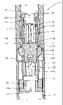
In the following is described an example of a preferred em-
bodiment illustrated in the enclosed drawings, where:
Fig. 1 shows a longitudinal section of a valve in accordance
with the invention in a closed position;
Fig. 2 shows the valve of fig. 1 where the body of second
valve is displaced from a second valve seat; and
Fig. 3 shows the valve of fig. 1 where the body of the first
valve is displaced from a first valve seat.

CA 02721468 2010-05-07
WO 2008/085057 PCT/N02008/000002
4
In the drawings, the reference numeral 1 indicates a dual di-
rectional downhole overpressure valve comprising a valve
housing 2, a first valve body 4 and a second valve body 6.
The valve housing 2, which may be a part of an adjacent pipe
portion, is shaped inside with a first valve seat 8 in the
form of a conical parapet in the wall of the valve housing 2.
The first valve body 4 is clamped in the valve housing 1 be-
tween the first valve seat 8 and a first holder 10 which is
screwed into the first bore 12 of the valve housing 1, the
first holder 10 being formed with a central bore 14 there-
through.
The first valve body 4 comprises a central bore 16 there-
through, into which the guide bushing 18 of the first holder
10 displaceably extends. At the first valve seat 8, the first
valve body 4 is formed with an outside diameter being some-
what smaller than a second bore 20 of the valve housing 2.
The second bore 20 has a somewhat larger diameter than the
first bore 12.
At its mid-portion 22, the first valve body 4 is allocated a
relatively thin-walled barrel-shaped portion. The mid-portion
22 is provided with a number of longitudinal recesses 24 sur-
rounding the central through opening 16.
The function of the recesses 24 is dual. The recesses 24 pro-
vide a flow path between the through opening 16 and an annu-
lus 25 between the first valve body 4 and the valve housing
2. Further, the recesses 24 weakens the axial strength of the
barrel-shaped mid-portion 22, as the mid-portion 22 thereby
constitutes a spring which under axial loading is resilient
shortened coincident with a resilient deflection of the mate-
rial in the mid-portion 22 between the recesses 24.
RECTIFIED SHEET (RULE 91)

CA 02721468 2010-05-07
WO 2008/085057 PCT/N02008/000002
The closing power of the first valve body 4 against the first
valve seat 8 is thus among other tings determined by the num-
ber of recesses 24 in the mid-portion 22, the wall thickness,
and by the relative distance of the first holder 10 to the
5 first valve seat 8.
The second valve body 6 is clamped between a second valve
seat 26 positioned in the first valve body 4 at the through
opening 16 adjacent the first valve'seat 8, and a second
holder 28 being screwed into the third bore 30 of the valve
housing 2.
The second holder 28 is in the same manner as the first
holder provided with a central bore 32 and a guide bushing
34, as the guide bushing 34 extends displaceably into a cen-
tral bore 36 in the second valve body 6. The central bore 36
is in the second valve body 6 is not a through bore, but runs in
to a pressure surface 38.
The mid-portion 40 of the second valve body 6 is also formed
with a relatively thin-walled barrel-shape and also provided
with longitudinal recesses 42.
In this preferred embodiment, the second valve body 6 is pro-
vided with more recesses 42 than the number of recesses 24 in
the first valve body 4. The second valve body 6 therefore ex-
erts a closing force against the second valve seat 26, which
is. considerably less than the closing force of the first
valve body 4 against the first valve seat 8.
A guide portion 44 of the second valve body 6 extends with a
radial clearance into the through opening 16 of the first
valve body 4. The guide portion 44 is provided with a trans-
verse slot 46.

CA 02721468 2010-05-07
WO 2008/085057 PCT/N02008/000002
6
The transverse slot 46 is arranged to be able to prevent the
second valve body 6 being able to rotate during a possible
drilling of the second valve body 6 once the cement has hard-
ened after the concrete is poured.
Fig. 1 shows the valve 1 in a closed position where the first.
valve body 4 abuts closingly against the first valve seat 8,
and the second valve body 6 abuts closingly against the sec-
ond valve seat 26.
When fluid flows into the through opening 16 of the first
valve body and the fluid pressure is increased, the second
valve body 6 will, due to liquid pressure against the guide
portion 44 at a given pressure being displaced away from the
second valve seat 26, as the mid portion 40 of the second
valve body 6 is resilient shortened.
Fluid may therefore flow through the valve 1 via the central
bore 14, the central opening 16, the second valve seat 26, an
annulus 48 encircling the mid-portion 40 of the second valve
body 6, the recesses 42, the central bore 36 and the central
bore 32, see fig. 2.
The valve 1 closes when the pressure is reduced.
When the fluid pressure in the central bore 36 in the second
valve body 6 is increased, the pressure acting against, among
other things, the pressure surface 38 will be transferred via
the second valve seat 26 to the first valve body 4 and tend
to displace this away from the first valve seat 8. At a given
pressure, the fluid pressure will overcome the force from the
mid-portion of the second valve body 6, whereby the first
valve body 4 is displaced out from the first valve seat 8 at
the same time as the second valve body 6 follows and is dis-
placed somewhat out beyond the guide bushing 34 of the second
holder 28, see fig. 3.
RECTIFIED SHEET (RULE 91)

CA 02721468 2010-05-07
WO 2008/085057 PCT/N02008/000002
7
Fluid may now flow through the valve 1 via the central bores
32, 36, the recesses 42, the second annulus 48, the first
valve seat 8, the first annulus 25, the recesses 24, the cen-
tral opening 16 and the central bore 14.
s The valve bodies 4 and 6 are advantageously produced from a
synthetic material or a metal, which may easily be removed
e.g. by drilling.

Representative Drawing
A single figure which represents the drawing illustrating the invention.
Administrative Status

2024-08-01:As part of the Next Generation Patents (NGP) transition, the Canadian Patents Database (CPD) now contains a more detailed Event History, which replicates the Event Log of our new back-office solution.

Please note that "Inactive:" events refers to events no longer in use in our new back-office solution.

For a clearer understanding of the status of the application/patent presented on this page, the site Disclaimer , as well as the definitions for Patent , Event History , Maintenance Fee  and Payment History  should be consulted.

Event History

Description Date
Time Limit for Reversal Expired 2023-07-07
Letter Sent 2023-01-09
Letter Sent 2022-07-07
Letter Sent 2022-01-07
Common Representative Appointed 2019-10-30
Change of Address or Method of Correspondence Request Received 2018-06-11
Grant by Issuance 2015-06-23
Inactive: Cover page published 2015-06-22
Pre-grant 2015-04-08
Inactive: Final fee received 2015-04-08
Notice of Allowance is Issued 2015-02-10
Letter Sent 2015-02-10
Notice of Allowance is Issued 2015-02-10
Inactive: QS passed 2014-10-31
Inactive: Approved for allowance (AFA) 2014-10-31
Amendment Received - Voluntary Amendment 2014-08-15
Inactive: S.30(2) Rules - Examiner requisition 2014-02-26
Inactive: Report - No QC 2014-02-24
Inactive: First IPC assigned 2013-09-26
Inactive: IPC assigned 2013-09-26
Letter Sent 2012-11-30
Request for Examination Requirements Determined Compliant 2012-11-21
All Requirements for Examination Determined Compliant 2012-11-21
Request for Examination Received 2012-11-21
Letter Sent 2012-03-08
Letter Sent 2011-02-22
Inactive: Single transfer 2011-02-03
Inactive: Cover page published 2010-12-14
Inactive: Notice - National entry - No RFE 2010-12-10
Inactive: First IPC assigned 2010-12-07
Inactive: IPC assigned 2010-12-07
Application Received - PCT 2010-12-07
Correct Applicant Request Received 2010-07-16
Inactive: Declaration of entitlement - PCT 2010-06-02
National Entry Requirements Determined Compliant 2010-05-07
Application Published (Open to Public Inspection) 2009-07-17

Abandonment History

There is no abandonment history.

Maintenance Fee

The last payment was received on 2014-12-30

Note : If the full payment has not been received on or before the date indicated, a further fee may be required which may be one of the following

  • the reinstatement fee;
  • the late payment fee; or
  • additional fee to reverse deemed expiry.

Please refer to the CIPO Patent Fees web page to see all current fee amounts.

Owners on Record

Note: Records showing the ownership history in alphabetical order.

Current Owners on Record
WELLTEC A/S
Past Owners on Record
OLAV EVERTSEN
STEFFEN EVERTSEN
Past Owners that do not appear in the "Owners on Record" listing will appear in other documentation within the application.
Documents

To view selected files, please enter reCAPTCHA code :


To view images, click a link in the Document Description column. To download the documents, select one or more checkboxes in the first column and then click the "Download Selected in PDF format (Zip Archive)" or the "Download Selected as Single PDF" button.

List of published and non-published patent-specific documents on the CPD .

If you have any difficulty accessing content, you can call the Client Service Centre at 1-866-997-1936 or send them an e-mail at CIPO Client Service Centre.


Document
Description 
Date
(yyyy-mm-dd) 
Number of pages   Size of Image (KB) 
Claims 2010-05-07 2 43
Description 2010-05-07 7 238
Drawings 2010-05-07 3 101
Abstract 2010-05-07 1 66
Representative drawing 2010-12-14 1 17
Cover Page 2010-12-14 1 46
Claims 2014-08-15 1 34
Representative drawing 2015-06-04 1 17
Cover Page 2015-06-04 1 46
Notice of National Entry 2010-12-10 1 193
Courtesy - Certificate of registration (related document(s)) 2011-02-22 1 103
Reminder - Request for Examination 2012-09-10 1 118
Acknowledgement of Request for Examination 2012-11-30 1 175
Commissioner's Notice - Application Found Allowable 2015-02-10 1 162
Commissioner's Notice - Maintenance Fee for a Patent Not Paid 2022-02-18 1 542
Courtesy - Patent Term Deemed Expired 2022-08-04 1 537
Commissioner's Notice - Maintenance Fee for a Patent Not Paid 2023-02-20 1 541
PCT 2010-06-23 1 27
Correspondence 2010-06-02 2 66
PCT 2010-05-07 3 128
Correspondence 2010-07-16 5 231
Fees 2014-12-30 1 26
Correspondence 2015-04-08 2 58