Note: Descriptions are shown in the official language in which they were submitted.
CA 02721495 2010-10-14
WO 2009/146171
PCT/US2009/040548
A. TITLE ¨ ARTICULATED DEVICE WITH VISUALIZATION SYSTEM
B. CROSS REFERENCE TO RELATED APPLICATIONS
[0001] This application claims priority to U.S. Provisional Application No.
61/044,783 filed on April 14, 2008.
C.-E. Not Applicable
F. BACKGROUND
[0002] This application discloses an invention that is related, generally and
in
various embodiments, to a multi-linked robotic device, a continuum robot, or
other
highly articulated device having a visualization system. Typically, physicians
and
other health care professionals must dispense saline over visualization
devices to
maintain visibility during surgery and/or other exploratory procedures.
However, the
visualization device may be used in certain regions, such as cardiac areas,
where
dispersal of saline is not practical or safe.
G. SUMMARY
[0003] Before the present methods are described, it is to be understood that
this
invention is not limited to the particular systems, methodologies or protocols
described, as these may vary. It is also to be understood that the terminology
used
herein is for the purpose of describing particular embodiments only, and is
not
intended to limit the scope of the present disclosure which will be limited
only by the
appended claims.
[0004] It must be noted that as used herein and in the appended claims, the
singular forms "a," "an," and "the" include plural reference unless the
context clearly
dictates otherwise. Unless defined otherwise, all technical and scientific
terms used
herein have the same meanings as commonly understood by one of ordinary skill
in
the art. As used herein, the term "comprising" means "including, but not
limited to."
[0005] In an embodiment, an articulated device may include a first steerable
multi-linked mechanism and a second steerable multi-linked mechanism. The
second
steerable multi-linked mechanism may include a first link, a plurality of
intermediate
links and a second link movably coupled to a second one of the intermediate
links. A
first one of the intermediate links may be movably coupled to the first link.
The
articulated device may include a camera located within at least a portion of
the second
link and a protective shield connected to a distal end of the second link. The
protective
shield may surround at least a portion of the camera.
CA 02721495 2010-10-14
WO 2009/146171
PCT/US2009/040548
[0006] In an embodiment, a visualization system for a steerable multi-linked
device may include a first steerable multi-linked mechanism that defines a
first
plurality of grooves and a second steerable multi-linked mechanism that
defines a
second plurality of grooves. The second steerable multi-linked mechanism may
include a first link, a plurality of intermediate links and a second link
movably coupled
to a second one of the intermediate links. A first one of the intermediate
links may be
movably coupled to the first link. The second link may include a protective
shield
connected to a distal end of the second link. The first plurality of grooves
and the
second plurality of grooves may cooperate to define one or more working ports
along a
length of the device. A camera may be located within at least a portion of the
second
link.
[0007] In an embodiment, a visualization system for a steerable multi-linked
device may include a steerable multi-linked device. The steerable multi-linked
device
may include a first steerable multi-linked mechanism that defines a first
plurality of
grooves, and a second steerable multi-linked mechanism that defines a second
plurality
of grooves. The first plurality of grooves and the second plurality of grooves
may
cooperate to define one or more working ports along a length of the device. A
camera
may be connected to one or more image fibers, and the one or more image fibers
may
occupy one or more of the working ports.
[0008] In an embodiment, a visualization system for a steerable multi-linked
device may include a steerable multi-linked device which may include a first
steerable
multi-linked mechanism that defines a first plurality of grooves, and a second
steerable
multi-linked mechanism that defines a second plurality of grooves. The first
plurality
of grooves and the second plurality of grooves may cooperate to define one or
more
working ports along a length of the device. A camera may be connected to one
or more
image fibers. The one or more image fibers may be enclosed in a sheath, and
the
sheath enclosed image fibers may occupy one or more of the working ports.
H. BRIEF DESCRIPTION OF DRAWINGS
[0009] Various embodiments of the invention are described herein by way of
example in conjunction with the following figures.
[00101 FIGS. IA and I B illustrate various embodiments of a steerable multi-
linked device.
[0011] FIG. 2 illustrates various embodiments of a core mechanism of the
device of FIG I.
-2-
CA 02721495 2010-10-14
WO 2009/146171
PCT/US2009/040548
[0012] FIGS. 3A-3C illustrate various embodiments of a proximal link of the
core mechanism.
[0013] FIGS. 4A-4C illustrate various embodiments of an intermediate link of
the core mechanism.
[0014] FIGS. 5A-5C illustrate various embodiments of a distal link of the core
mechanism.
[0015] FIG. 6 illustrates various embodiments of a sleeve mechanism of the
device of FIG I.
[0016] FIGS. 7A-7C illustrate various embodiments of a proximal link of the
sleeve mechanism.
100171 FIGS. 8A-8C illustrate various embodiments of an intermediate link of
the sleeve mechanism.
[0018] FIGS. 9A-9D illustrate various embodiments of a distal link of the
sleeve mechanism.
[0019] FIG. 10 illustrates various embodiments of a motion sequence of the
device of Figure I.
[0020] FIG. 11 illustrates various embodiments of a steerable multi-linked
device traversing a path having tight curvatures.
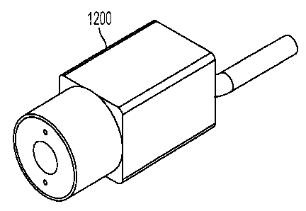
[0021] FIG. 12 illustrates an exemplary camera according to an embodiment.
[0022] FIGS. 13A and 13B illustrate an exemplary camera housed in a link
according to an embodiment.
[0023] FIG. 14A illustrates one or more image fibers enclosed by an
exemplary sheath according to an embodiment.
[0024] FIG. 14B illustrates an exemplary sheath and protective shield filled
with a fluid according to an embodiment.
[0025] FIG. I5A and 1513 illustrate an exemplary protective shield according
to an embodiment.
DETAILED DESCRIPTION
[0026] It is to be understood that at least some of the figures and
descriptions
of the invention have been simplified to focus on elements that are relevant
for a clear
understanding of the invention, while eliminating, for purposes of clarity,
other
elements that those of ordinary skill in the art will appreciate may also
comprise a
portion of the invention. However, because such elements are well known in the
art,
-3-
CA 02721495 2010-10-14
WO 2009/146171
PCT/US2009/040548
and because they do not necessarily facilitate a better understanding of the
invention, a
description of such elements is not provided herein.
[0027] According to various embodiments, the invention described herein may
be utilized to control movement of an articulated device, which in the figures
and
description herein is described as a steerable multi-linked device. For ease
of
explanation purposes, the invention will be described in the context of its
use with
various embodiments of the steerable multi-linked device described herein.
However,
one skilled in the art will appreciate that the invention may be utilized with
other types
of multi-linked devices as well as other types of devices such as, but not
limited to,
endoscopes, highly articulated devices and/or the like.
[0028] FIGS. IA and 1B illustrate various embodiments of a highly articulated
device 10. According to various embodiments, the device may be a steerable
multi-
linked device such as a snake-like robot, a continuum robot or the like.
Various
embodiments of the device 10 may be utilized for medical procedures (e.g., as
a
robotic bore, positioning device, ablation tool, camera or instrument support,
or
guidance system for minimally invasive procedures), for surveillance
applications, for
inspection applications, for search and rescue applications, etc. For purposes
of clarity
only, the utility of the device 10 will be described hereinbelow in the
context of its
applicability to medical procedures. However, a person skilled in the art will
appreciate that the device 10 can be utilized in a variety of different
applications.
100291 The device 10 comprises a first mechanism 12 and a second mechanism
14. According to various embodiments, a mechanism may be a series of
articulated
links, a snake-like robot, a continuum robot or the like. According to various
embodiments, the second mechanism 14 is structured and arranged to receive and
surround the first mechanism 12 as shown in FIG. I B. Thus, the first
mechanism and
second mechanism may be concentric. For such embodiments, the first mechanism
12
may be considered the inner mechanism or the core mechanism, and the second
mechanism 14 may be considered the outer mechanism or the sleeve mechanism.
According to other embodiments, the first and second mechanisms 12, 14 may be
structured and arranged to have a relationship other than a concentric
relationship. For
example, one skilled in the art will appreciate that, according to various
embodiments,
the first and second mechanisms 12, 14 may be structured and arranged to
operate in a
side-by-side arrangement, where the first mechanism 12 operates adjacent to
the
second mechanism 14. According to various embodiments, additional and/or
alternate
-4-
CA 02721495 2010-10-14
WO 2009/146171
PCT/US2009/040548
configurations may be used within the scope of this disclosure. According to
various
embodiments, a three-dimensional space 240 may be provided between the first
and
second mechanisms. This space will be described in more detail below.
100301 As described in more detail hereinbelow, the first mechanism 12 may
operate in either a rigid mode or a limp mode, the second mechanism 14 may
operate
in either a rigid mode or a limp mode, and the first and second mechanisms 12,
14 may
operate independent of one another. Both the first mechanism 12 and the second
mechanism 14 may be steerable mechanisms. Accordingly, it will be appreciated
that
the device 10 may be utilized to navigate a luminal space as well as any three-
dimensional path within an intracavity space. According to various
embodiments, the
device 10 may advance by alternating the operation of the first mechanism 12
and the
second mechanism 14 between a limp mode and a rigid mode.
100311 According to various embodiments, the device 10 may also comprise
one or more cables. According to various embodiments, one or more of the
cables
may be steering cables and/or tensioning cables. For example, the device may
include
three cables for steering and tensioning
100321 FIG. 2 illustrates various embodiments of the first mechanism 12 of the
device 10. The first mechanism 12 is a multi-linked mechanism and includes a
first
end 24 and a second end 26. The first end 24 may be considered the proximal
end and
the second end 26 may be considered the distal end. The first mechanism 12 may
comprise a first link 28, a second link 30, and one or more intermediate links
32
between the first and second links 28, 30. The first link 28 may be considered
the
proximal link, and the second link 30 may be considered the distal link.
100331 FIGS. 3A-3C illustrate various embodiments of the first link 28 (inner
proximal link) of the first mechanism 12. The first link 28 includes a first
end 34 and a
second end 36, and defines a longitudinal axis 38 that passes through the
center of the
first end 34 and the center of the second end 36 as shown in FIG. 3B. The
first link 28
may be fabricated from any suitable material. According to various
embodiments, the
first link 28 is fabricated from a fiber reinforced material such as, for
example,
G10/FR4 Garolitet. The first link 28 has a generally cylindrical shaped
exterior and
is described in more detail hereinbelow.
100341 The first link 28 comprises a first portion 40 and a second portion 42.
The first portion 40 may be considered the proximal portion and the second
portion 42
may be considered the distal portion. The first portion 40 may be fabricated
integral
-5-
CA 02721495 2010-10-14
WO 2009/146171
PCT/US2009/040548
with the second portion 42. The first portion 40 has a cylindrical shaped
exterior, and
extends from the first end 34 of the first link 28 toward the second end 36 of
the first
link 28. According to various embodiments, the diameter of the first portion
40 may
be on the order of approximately 6.35 millimeters. Other sizes are possible.
[00351 The second portion 42 has a generally cylindrically shaped exterior,
with other features described below. The second portion 42 has a cylindrically
shaped
exterior where it contacts the first portion 40, and tapers toward the second
end 36 of
the first link 28. The second portion 42 may be shaped in the form of a
generally
segmented hemisphere at the second end 36 of the first link 28. According to
various
embodiments, the diameter of the second portion 42 may be on the order of
approximately 4.75 millimeters where it contacts the first portion 40. Other
sizes are
possible.
100361 The second portion 42 comprises a first surface 44. The first surface
44
may be considered the outer surface of the second portion 42. The second
portion 42
defines a first groove 46 parallel to the longitudinal axis 38 along the first
surface 44, a
second groove 48 parallel to the longitudinal axis 38 along the first surface
44, and a
third groove 50 parallel to the longitudinal axis 38 along the first surface
44. Each of
the first, second and third grooves 46, 48, 50 extend along the first surface
44 toward
the second end 36 of the first link 28. The first, second and third grooves
46, 48, 50
may be semi-tubular shaped and may be evenly spaced about the first surface 44
of the
second portion 42 of the first link 28 as shown in FIG. 3C. According to
various
embodiments, the first, second, and third grooves 46, 48, 50 may be configured
in the
shape of a segmented cylinder. The size of each of the grooves 46, 48, 50 may
be
identical to one another or may be different from one another. For example,
according
to various embodiments, the first and second grooves 46, 48 may be configured
as
segments of a cylinder having a diameter on the order of approximately 1.25
millimeters, and the third groove 50 may be configured as a segment of a
cylinder
having a diameter on the order of approximately 2.50 millimeters. The length
of the
first link 28 may be on the order of approximately 65 millimeters. However,
one
skilled in the art will appreciate that the length or diameter of the first
link 28 can vary
based on the application.
100371 The first link 28 also defines a passage 52 extending from the first
end
34 to the second end 36 along the longitudinal axis 38 as shown in FIG. 3B.
The
passage 52 is of a size sufficient to allow at least one cable to pass
therethrough.
-6-
CA 02721495 2010-10-14
WO 2009/146171
PCT/US2009/040548
According to various embodiments, the passage 52 may be of a sufficient size
to allow
a tensioning cable to pass therethrough. According to various embodiments, the
passage 52 is generally configured as a complex shape that comprises a
combination of
a first cylinder 54 that extends from the first end 34 toward the second end
36, and a
second cylinder 56 that extends from the first cylinder 54 toward the second
end 36.
The diameter of the first cylinder 54 is larger than the diameter of the
second cylinder
56. For example, according to various embodiments, the first cylinder 54 may
have a
diameter on the order of approximately 3.20 millimeters and the second
cylinder 56
may have a diameter on the order of approximately 1.50 millimeters. Other
sizes are
possible.
100381 FIGS. 4A-4C illustrate various embodiments of one of the intermediate
links 32 (inner intermediate link) of the first mechanism 12. The intermediate
link 32
is representative of the other intermediate links 32. The intermediate link 32
includes
a first end 58 and a second end 60, and defines a longitudinal axis 62 that
passes
through the center of the first end 58 and the center of the second end 60 as
shown in
FIG. 4B. The intermediate link 32 may be fabricated from any suitable
material.
According to various embodiments, the intermediate link 32 is fabricated from
a fiber
reinforced material such as, for example, Gl0/FR4 Garolite . The intermediate
link
32 has a generally bullet-shaped exterior and is described in more detail
hereinbelow.
[00391 The intermediate link 32 comprises a first portion 64 and a second
portion 66. The first portion 64 may be considered the proximal portion and
the
second portion 66 may be considered the distal portion. The first portion 64
may be
fabricated integral with the second portion 66. The first portion 64 has a
generally
cylindrical shaped exterior, and extends from the first end 58 of the
intermediate link
32 toward the second end 60 of the intermediate link 32. According to various
embodiments, the second portion 66 has a generally cylindrically shaped
exterior
where it contacts the first portion 64, and tapers toward the second end 60 of
the
intermediate link 32. The exterior of the second portion 66 is configured in
the form
of a generally segmented hemisphere. According to various embodiments, the
diameter of the intermediate link 32 may be on the order of approximately 4.75
millimeters at the first end 58 thereof. The length of the intermediate link
32 may be
on the order of approximately 5.85 millimeters. However, one skilled in the
art will
appreciate that the length or diameter of the intermediate link 32 can vary
based on the
application.
-7-
CA 02721495 2010-10-14
WO 2009/146171
PCT/US2009/040548
100401 The intermediate link 32 also comprises a first surface 68 that extends
from the first end 58 of the intermediate link 32 to the second end 60 of the
intermediate link 32. The first surface 68 may be considered the outer surface
of the
intermediate link 32. The intermediate link 32 also defines a first groove 70
parallel to
the longitudinal axis 62 along the first surface 68, a second groove 72
parallel to the
longitudinal axis 62 along the first surface 68, and a third groove 74
parallel to the
longitudinal axis 62 along the first surface 68. Each of the first, second and
third
grooves 70, 72, 74 extend along the first surface 68 from the first end 58 of
the
intermediate link 32 toward the second end 60 of the intermediate link 32. The
first,
second and third grooves 70, 72, 74 may be semi-tubular shaped and may be
evenly
spaced about the first surface 68 of the intermediate link 32 as shown in FIG.
4C.
According to various embodiments, the first, second, and third grooves 70, 72,
74 may
be configured in the shape of a segmented cylinder. The size of each of the
grooves
70, 72, 74 may be identical to one another or may be different from one
another. For
example, according to various embodiments, the first and second grooves 70, 72
are
configured as segments of a cylinder having a diameter on the order of
approximately
1.75 millimeters at the first end 58 of the intermediate link 32, and the
third groove 74
is configured as a segment of a cylinder having a diameter on the order of
approximately 2.50 millimeters at the first end 58 of the intermediate link
32. The
first, second and third grooves 70, 72, 74 are each configured to receive and
partially
surround any of a variety of tools or instruments (e.g., ablation tools) which
may pass
from the first end 24 of the multi-linked device 10 to the second end 26 of
the multi-
linked device 10.
100411 The intermediate link 32 also defines a passage 76 extending from the
first end 58 to the second end 60 along the longitudinal axis 62 as shown in
FIG. 4B.
The passage 76 may be of a size sufficient to allow one or more cables to pass
therethrough. According to various embodiments, the passage 76 may be of a
size
sufficient to allow a tensioning cable to pass therethrough. According to
various
embodiments, the passage 76 is generally configured as a complex shape that
comprises a combination of a first segmented hemisphere 78 that extends from
the first
end 58 toward the second end 60, a second segmented hemisphere 80 that extends
from the first segmented hemisphere 78 toward the second end 60, a cylinder 82
that
extends from the second segmented hemisphere 80 toward the second end 60, and
a
third segmented hemisphere 84 that extends from the cylinder 82 to the second
end 60
-8-
CA 02721495 2010-10-14
WO 2009/146171
PCT/US2009/040548
of the intermediate link 32. According to various embodiments, the first
segmented
hemisphere 78 represents a portion of a sphere having a diameter on the order
of
approximately 4.75 millimeters, the second segmented hemisphere 80 represents
a
portion of a sphere having a diameter on the order of approximately 2.25
millimeters,
the cylinder 82 may have a diameter on the order of approximately 1.0
millimeter, and
the third segmented hemisphere 84 represents a portion of a sphere having a
diameter
on the order of approximately 2.25 millimeters. Other sizes are possible.
[0042] The first segmented hemisphere 78 of the passage 76 is configured to
receive the second end 36 of the first link 28 when the first link 28 is
coupled to the
intermediate link 32. Similarly, for a given intermediate link 32, the first
segmented
hemisphere 78 of the passage 76 is configured to receive the second end 60 of
another
intermediate link 32 when the other intermediate link 32 is coupled to the
given
intermediate link 32. The third segmented hemisphere 84 may serve to reduce
the
pinching or binding a cable when one intermediate link 32 moves relative to an
adjacent intermediate link 32 coupled thereto. Similarly, when the second link
30 is
coupled to a given intermediate link 32, the third segmented hemisphere 84 may
serve
to reduce the pinching or binding of a cable when the second link 30 moves
relative to
the given intermediate link 32.
100431 With the above described structure, the first link 28 may be coupled to
the intermediate link 32 by seating the second end 36 of the first link 28 in
the first
segmented hemisphere 78 of the passage 76 of the intermediate link 32. As the
convex
configuration of the second end 36 of the first link 28 generally corresponds
with the
concave configuration of the first segmented hemisphere 78 of the passage 76
of the
intermediate link 32, the first link 28 may be coupled to the intermediate
link 32 such
that the longitudinal axis 38 and the first, second and third grooves 46, 48,
50 of the
first link 28 are respectively aligned with the longitudinal axis 62 and the
first, second
and third grooves 70, 72, 74 of the intermediate link 32. The intermediate
link 32 may
be moved relative to the first link 28 such that the longitudinal axis 62 of
the
intermediate link 32 is not aligned with the longitudinal axis 38 of the first
link 28.
According to various embodiments, the configuration of the first link 28 and
the
intermediate link 32 allows for the intermediate link 32 to be moved relative
to the first
link 28 coupled thereto such that the longitudinal axis 38 of the first link
28 and the
longitudinal axis 62 of the intermediate link 32 are up to approximately 25
out of
alignment with one another. Similarly, one intermediate link 32 may be coupled
to
-9-
CA 02721495 2010-10-14
WO 2009/146171
PCT/US2009/040548
another intermediate link 32, and so on, by seating the second end 60 of one
intermediate link 32 in the first segmented hemisphere 78 of the passage 76 of
another
intermediate link 32. As the convex configuration of the second end 60 of the
intermediate link 32 generally corresponds with the concave configuration of
the first
segmented hemisphere 78 of the passage 76 of the intermediate link 32, the
intermediate links 32 may be coupled such that the respective longitudinal
axes 62 and
the respective first, second and third grooves 46, 48, 50 of the intermediate
links 32 are
aligned. The coupled intermediate links 32 may be moved relative to one
another such
that the respective longitudinal axes 62 of the coupled intermediate links 32
are not
aligned. According to various embodiments, the configuration of the coupled
intermediate links 32 allows for one intermediate link 32 to be moved relative
to an
adjacent intermediate link 32 coupled thereto such that the respective
longitudinal axes
62 are up to approximately 25 out of alignment with one another.
[0044] FIGS. 5A-5C illustrate various embodiments of the second link 30
(inner distal link) of the first mechanism 12. The second link 30 includes a
first end 86
and a second end 88, and defines a longitudinal axis 90 that passes through
the center
of the first end 86 and the center of the second end 88 as shown in FIG. 5B.
The
second link 30 may be fabricated from any suitable material. According to
various
embodiments, the second link 30 is fabricated from a thermoplastic material
such as,
for example, Delrin .
[00451 The second link 30 comprises a first portion 92 and a second portion
94. The first portion 92 may be considered the proximal portion and the second
portion 94 may be considered the distal portion. The first portion 92 may be
fabricated
integral with the second portion 94. The first portion 92 has a generally
cylindrical
shaped exterior, and extends from the first end 86 of the second link 30
toward the
second end 88 of the second link 30. According to various embodiments, the
second
portion 94 has a generally cylindrically shaped exterior where it contacts the
first
portion 92, and tapers toward the second end 88 of the second link 30. The
exterior of
the second portion 64 is configured in the form of a generally segmented cone.
According to various embodiments, the diameter of the second link 30 may be on
the
order of approximately 4.75 millimeters at the first end 86 thereof, and the
taper of the
second portion 94 may be at an angle of approximately 30 relative to the
exterior of
the first portion 92. The length of the second link 30 may be on the order of
-10-
CA 02721495 2010-10-14
WO 2009/146171
PCT/US2009/040548
approximately 5.90 millimeters. However, one skilled in the art will
appreciate that
the length or diameter of the second link 30 can vary based on the
application.
[0046] The second link 30 also comprises a first surface 96 that extends from
the first end 86 of the second link 30 to the second end 88 of the second link
30. The
first surface 96 may be considered the outer surface of the second link 30.
The second
link 30 also defines a first groove 98 parallel to the longitudinal axis 90
along the first
surface 96, a second groove 100 parallel to the longitudinal axis 90 along the
first
surface 96, and a third groove 102 parallel to the longitudinal axis 90 along
the first
surface 96. Each of the first, second and third grooves 98, 100, 102 extend
along the
first surface 96 from the first end 86 of the second link 30 toward the second
end 88 of
the second link 30. The first, second and third grooves 98, 100, 102 may be
semi-
tubular shaped and may be evenly spaced about the first surface 96 of the
second link
30 as shown in FIG. 5C. According to various embodiments, the first, second,
and
third grooves 98, 100, 102 may be configured in the shape of a segmented
cylinder.
The size of each of the grooves 98, 100, 102 may be identical to one another
or may be
different from one another. For example, according to various embodiments, the
first
and second grooves 98, 100 are configured as segments of a cylinder having a
diameter on the order of approximately 1.25 millimeters at the first end 86 of
the
second link 30, and the third groove 102 is configured as a segment of a
cylinder
having a diameter on the order of approximately 2.50 millimeters at the first
end 86 of
the second link 30. The first, second and third grooves 98, 100, 102 are each
configured to receive and partially surround any of a variety of tools or
instruments
(e.g., ablation tools) which may pass from the first end 24 of the multi-
linked device
10 to the second end 26 of the multi-linked device 10.
[0047] The second link 30 also defines a passage 104 extending from the first
end 86 to the second end 88 along the longitudinal axis 90 as shown in FIG.
5B. The
passage 104 may be of a size sufficient to allow at least one cable to pass
therethrough.
According to various embodiments, the passage 104 may be of a size sufficient
to
allow a tensioning cable to pass therethrough. According to various
embodiments, the
passage 104 is generally configured as a complex shape that comprises a
combination
of a first segmented hemisphere 106 that extends from the first end 86 toward
the
second end 88, a second segmented hemisphere 108 that extends from the first
segmented hemisphere 106 toward the second end 88, and a cylinder 110 that
extends
from the second segmented hemisphere 108 to the second end 88 of the second
link
-11-
CA 02721495 2010-10-14
WO 2009/146171
PCT/US2009/040548
30. According to various embodiments, the first segmented hemisphere 106
represents
a portion of a sphere having a diameter on the order of approximately 4.75
millimeters,
the second segmented hemisphere 108 represents a portion of a sphere having a
diameter on the order of approximately 2.50 millimeters, and the cylinder 110
may
have a diameter on the order of approximately 1.0 millimeter. The first
segmented
hemisphere 106 of the passage 104 may be configured to receive the second end
60 of
an intermediate link 32 when the intermediate link 32 is coupled to the second
link 30.
[0048] With the above described structure, an intermediate link 32 may be
coupled to the second link 30 by seating the second end 60 of the intermediate
link 32
in the first segmented hemisphere 106 of the passage 104 of the second link
30. As the
convex configuration of the second end 60 of the intermediate link 32
generally
corresponds with the concave configuration of the first segmented hemisphere
106 of
the passage 104 of the second link 30, the intermediate link 32 may be coupled
to the
second link 30 such that the longitudinal axis 62 and the first, second and
third grooves
70, 72, 74 of the intermediate link 32 are respectively aligned with the
longitudinal
axis 90 and the first, second and third grooves 98, 100, 102 of the second
link 30. The
second link 30 may be moved relative to the intermediate link 32 coupled
thereto such
that the respective longitudinal axes 62, 90 are not aligned. According to
various
embodiments, the configuration of the second link 30 allows for an
intermediate link
32 coupled thereto to be moved relative to the second link 30 such that the
respective
longitudinal axes 62, 90 are up to approximately 25 out of alignment with one
another.
[0049] FIG. 6 illustrates various embodiments of the second mechanism 14 of
the device 10. The second mechanism 14 is a multi-linked mechanism and
includes a
first end 120 and a second end 122. The first end 120 may be considered the
proximal
end and the second end 122 may be considered the distal end. The second
mechanism
14 comprises a first link 124, a second link 126, and any number of
intermediate links
128 between the first and second links 124, 126. The first link 124 may be
considered
the proximal link, and the second link 126 may be considered the distal link.
[0050] FIGS. 7A-7C illustrate various embodiments of the first link 124 (outer
proximal link) of the second mechanism 14. The first link 124 includes a first
end 130
and a second end 132, and defines a longitudinal axis 134 that passes through
the
center of the first end 130 and the center of the second end 132 as shown in
FIG. 7B.
The first link 124 may be fabricated from any suitable material. According to
various
-12-
CA 02721495 2010-10-14
WO 2009/146171
PCT/US2009/040548
embodiments, the first link 124 is fabricated from a stainless steel material
such as, for
example, 316 stainless steel. The first link 124 has a generally bullet-shaped
exterior
and is described in more detail hereinbelow.
10051] The first link 124 comprises a first portion 136 and a second portion
138. The first portion 136 may be considered the proximal portion and the
second
portion 138 may be considered the distal portion. The first portion 136 may be
fabricated integral with the second portion 138. The first portion 136 has a
cylindrical
shaped exterior, and extends from the first end 130 of the first link 124
toward the
second end 132 of the first link 124. According to various embodiments, the
diameter
of the first portion 136 may be on the order of approximately 12.70
millimeters. Other
sizes are possible.
[0052] The second portion 138 has a generally cylindrically shaped exterior.
The second portion 138 has a cylindrically shaped exterior where it contacts
the first
portion 136, and tapers toward the second end 132 of the first link 124. The
second
portion 138 may be shaped in the form of a generally segmented hemisphere at
the
second end 132 of the first link 124. According to various embodiments, the
diameter
of the second portion 138 may be on the order of approximately 9.50
millimeters
where it contacts the first portion 136. Other sizes and shapes are possible.
10053] The second portion 138 comprises a first surface 140. The first surface
140 may be considered the outer surface of the second portion 138. The second
portion 138 defines a first groove 142 along the first surface 140, a second
groove 144
along the first surface 140, and a third groove 146 along the first surface
140. Each of
the first, second and third grooves 142, 144, 146 are oblique relative to the
longitudinal
axis 134 and extend along the first surface 140 toward the second end 132 of
the first
link 124. According to various embodiments, each of the grooves 142, 144, 146
are
oriented at an angle on the order of approximately 15 relative to the
longitudinal axis
134. As shown in FIG. 7C, the first, second and third grooves 142, 144, 146
may be
evenly spaced about the first surface 140 of the first link 124. According to
various
embodiments, the first, second, and third grooves 142. 144, 146 may be
configured in
the shape of a segmented cylinder. The size of each of the grooves 142, 144,
146 may
identical to one another or may be different from one another. For example,
according
to various embodiments, each of the grooves 142, 144, 146 are configured as
segments
of respective cylinders having diameters on the order of approximately 3.0
millimeters.
The first, second and third grooves 142, 144, 146 are each configured to
facilitate the
-13-
CA 02721495 2010-10-14
WO 2009/146171
PCT/US2009/040548
introduction of various tools or instruments (e.g., ablation tools) into the
multi-linked
device 10. The length of the first link 124 may be on the order of
approximately 18.5
millimeters. However, one skilled in the art will appreciate that the length
or diameter
of the first link 124 can vary based on the application.
[0054] The first link 124 also defines a passage 148 extending from the first
end 130 to the second end 132 along the longitudinal axis 134 as shown in FIG.
7B.
The passage 148 is of a size sufficient to allow the first mechanism 12 to
pass
therethrough. According to various embodiments, the passage 148 is generally
configured as a complex shape that comprises a combination of a segmented cone
150
that extends from the first end 130 toward the second end 132, and a cylinder
152 that
extends from the segmented cone 150 to the second end 132 of the first link
124.
According to various embodiments, the segmented cone 150 has a diameter on the
order of approximately 7.0 millimeters at the first end 130 of the first link
124, and
may be tapered at an angle on the order of approximately 450 relative to the
longitudinal axis 134. The cylinder 152 may have a diameter on the order of
approximately 5.50 millimeters. Other dimensions are possible.
[0055] The first link 124 also defines a first through-hole 154, a second
through-hole 156, and a third through-hole 158. (See FIG. 7C). The first
through-hole
154 is substantially parallel to the longitudinal axis 134, extends from the
first portion
136 toward the second end 132, and is positioned between the passage 148 and
the
first surface 140. The second through-hole 156 is substantially parallel to
the
longitudinal axis 134, extends from the first portion 136 to the second end
132, and is
positioned between the passage 148 and the first surface 140. The third
through-hole
158 is substantially parallel to the longitudinal axis 134, extends from the
first portion
136 to the second end 132, and is positioned between the passage 148 and the
first
surface 140. The first, second and third through-holes 154, 156, 158 are
generally
cylindrically shaped. According to various embodiments, the through-holes 154,
156,
158 are evenly spaced from one another as shown in FIG. 7C. The size of each
of the
through-holes 154, 156, 158 may be identical to one another or may be
different from
one another. For example, according to various embodiments, the respective
diameters associated with the through-holes 154, 156, 158 may each be on the
order of
approximately 1.20 millimeters. The first through-hole 154 is configured to
receive
and surround a cable. The second through-hole 156 is configured to receive and
surround a cable. The third through-hole 158 is configured to receive and
surround a
-14-
CA 02721495 2010-10-14
WO 2009/146171
PCT/US2009/040548
cable. The first, second and third through-holes 154, 156, 158 may serve as
guidepaths for movement of the cables.
[00561 FIGS. 8A-8C illustrate various embodiments of one of the intermediate
links 128 (outer intermediate link) of the second mechanism 14. The
intermediate link
128 is representative of the other intermediate links 128. The intermediate
link 128
includes a first end 160 and a second end 162, and defines a longitudinal axis
164 that
passes through the center of the first end 160 and the center of the second
end 162 as
shown in FIG. 8C. The intermediate link 128 may be fabricated from any
suitable
material. According to various embodiments, the intermediate link 128 is
fabricated
from a polymer thermosplastic material such as, for example, polysulfone. The
intermediate link 128 has a generally bullet-shaped exterior and is described
in more
detail hereinbelow.
[00571 The intermediate link 128 comprises a first portion 166 and a second
portion 168. The first portion 166 may be considered the proximal portion and
the
second portion 168 may be considered the distal portion. The first portion 166
may be
fabricated integral with the second portion 168. The first portion 166 has a
generally
cylindrical shaped exterior, and extends from the first end 160 of the
intermediate link
128 toward the second end 162 of the intermediate link 128. According to
various
embodiments, the second portion 168 has a generally cylindrically shaped
exterior
where it contacts the first portion 166, and tapers toward the second end 162
of the
intermediate link 128. The exterior of the second portion 168 is configured in
the form
of a generally segmented hemisphere. According to various embodiments, the
diameter of the intermediate link 128 is on the order of approximately 9.65
millimeters
at the first end 160 thereof. The length of the intermediate link 128 may be
on the
order of approximately 8.40 millimeters. However, one skilled in the art will
appreciate that the dimensions of the intermediate link 128 can vary based on
the
application.
[00581 The intermediate link 128 also comprises a first surface 170 that
extends from the first end 160 of the intermediate link 128 to the second end
162 of the
intermediate link 128, and a second surface 170 that extends from the first
end 160 of
the intermediate link 128 to the second end 162 of the intermediate link 128.
The first
surface 170 may be considered the outer surface of the intermediate link 128,
and the
second surface 172 may be considered the inner surface of the intermediate
link 128.
The intermediate link 32 also defines a first groove 174 substantially
parallel to the
-15-
CA 02721495 2010-10-14
WO 2009/146171
PCT/US2009/040548
longitudinal axis 164 along the second surface 172, a second groove 176
substantially
parallel to the longitudinal axis 164 along the second surface 172, and a
third groove
178 substantially parallel to the longitudinal axis 164 along the second
surface 172.
Each of the first, second and third grooves 174, 176, 178 extend along the
second
surface 172 toward the second end 162 of the intermediate link 128. The first,
second
and third grooves 174, 176, 178 may be semi-tubular shaped and may be evenly
spaced about the second surface 172 of the intermediate link 128 as shown in
FIG. 8C.
According to various embodiments, the first, second, and third grooves 174,
176, 178
may be configured in the shape of a segmented cylinder. The size of each of
the
grooves 174, 176, 178 may be identical to one another or may be different from
one
another. For example, according to various embodiments, the first and second
grooves
174, 176 are configured as segments of cylinders having diameters on the order
of
approximately 1.75 millimeters at the first end 160 of the intermediate link
128, and
the third groove 178 is configured as a segment of a cylinder having a
diameter on the
order of approximately 2.50 millimeters at the first end 160 of the
intermediate link
128. The first, second and third grooves 174, 176, 178 are each configured to
receive
and partially surround any of a variety of tools or instruments (e.g.,
ablation tools)
which may pass from the first end 24 of the multi-linked device 10 to the
second end
26 of the multi-linked device 10.
100591 The intermediate link 128 also defines a passage 180 extending from
the first end 160 to the second end 162 along the longitudinal axis 164 as
shown in
FIG. 8B. The passage 180 is of a size sufficient to allow the first mechanism
12 to
pass therethrough. According to various embodiments, the passage 180 is
generally
configured as a complex shape that comprises a combination of a segmented
hemisphere 182 that extends from the first end 160 toward the second end 162,
a first
segmented cone 184 that extends from the segmented hemisphere 182 toward the
second end 162, a cylinder 186 that extends from the first segmented cone 184
toward
the second end 162, and a second segmented cone 188 that extends from the
cylinder
186 to the second end 162 of the intermediate link 128. According to various
embodiments, the segmented hemisphere 182 represents a portion of a sphere
having a
diameter on the order of approximately 9.65 millimeters, the first segmented
cone 184
is tapered at an angle on the order of approximately 15 relative to the
longitudinal
axis 164, the cylinder 186 has a diameter on the order of approximately 5.50
millimeters, and the second segmented cone 188 is tapered at an angle on the
order of
-16-
CA 02721495 2010-10-14
WO 2009/146171
PCT/US2009/040548
approximately 15 relative to the longitudinal axis 164. The segmented
hemisphere
182 of the passage 180 is configured to receive the second end 132 of the
first link 124
when the first link 124 is coupled to the intermediate link 128. Similarly,
for a given
intermediate link 128, the segmented hemisphere 182 of the passage 180 is
configured
to receive the second end 162 of another intermediate link 128 when the other
intermediate link 128 is coupled to the given intermediate link 128.
[00601 The intermediate link 128 also defines a first through-hole 190, a
second through-hole 192, and a third through-hole 194. (See FIG. 8C). The
first
through-hole 190 is substantially parallel to the longitudinal axis 164,
extends from the
first portion 166 toward the second end 162, and is positioned between the
passage 180
and the first surface 170. The second through-hole 192 is substantially
parallel to the
longitudinal axis 164, extends from the first portion 166 to the second end
162, and is
positioned between the passage 180 and the first surface 170. The third
through-hole
194 is substantially parallel to the longitudinal axis 164, extends from the
first portion
166 to the second end 162, and is positioned between the passage 180 and the
first
surface 170. The first, second and third through-holes 190, 192, 194 are
generally
cylindrically shaped. According to various embodiments, the through-holes 190,
192,
194 are evenly spaced from one another. The size of each of the through-holes
190,
192, 194 may be identical to one another or may be different from one another.
For
example, according to various embodiments, the respective diameters associated
with
the through-holes 190, 192, 194 may each be on the order of approximately 1.25
millimeters. The first through-hole 190 is configured to receive and surround
a cable.
The second through-hole 192 is configured to receive and surround a cable. The
third
through-hole 194 is configured to receive and surround a cable. The first,
second and
third through-holes 190, 192, 194 may serve as guidepaths for movement of the
cables.
100611 As shown in FIG. 8C, the intermediate link 128 also defines first,
second and third indents 196, 198, 200 at the second end 162 thereof
resulting, in part,
from the combination of the taper associated with the second portion 168 and
the
configuration and orientation of the first, second, and third grooves 174,
176, 178. The
first, second and third indents 196, 198, 200 may be evenly spaced about the
second
end 162 of the intermediate link 128 as shown in FIG. 8C. The first, second
and third
indents 196, 198, 200 may serve to reduce the pinching or binding of various
tools or
instruments (e.g., ablation tools) when one intermediate link 128 of the
second
mechanism 14 is moved relative to another intermediate link 128 coupled
thereto.
-17-
CA 02721495 2010-10-14
WO 2009/146171
PCT/US2009/040548
100621 The intermediate link 128 also defines fourth, fifth and sixth indents
202, 204, 206 at the second end 162 thereof resulting from the combination of
the
taper associated with the second portion 168 and the configuration and
orientation of
the first, second, and third through-holes 190. 192, 194. The fourth, fifth
and sixth
indents 202, 204, 206 may be evenly spaced about the second end 162 of the
intermediate link 128, and may be evenly spaced from the first, second and
third
indents 196, 198, 200 as shown in FIG. 8C. The fourth, fifth and sixth indents
202,
204, 206 may serve to reduce the pinching or binding of the cables when one
intermediate link 128 of the second mechanism 14 is moved relative to another
intermediate link 128 coupled thereto.
100631 According to various embodiments, an intermediate link 128 may also
define an opening (not shown) that extends from the second surface 172 or from
one of
the grooves 174, 176, 178 to the first surface 170 of the intermediate link
128. The
intermediate link 128 may have any number of such openings, and any number of
the
intermediate links 128 may have such openings. Referring to FIGs. 2 and 4, the
opening may be utilized as an exit point for a tool or instrument which may
pass from
the first end 24 of the multi-linked device 10 toward the second end 26 of the
multi-
linked device 10. For such embodiments, the respective intermediate link 128
may be
positioned proximate to the second link 126 of the second mechanism 14. The
opening may be oriented at any angle relative to the longitudinal axis 134 of
the
intermediate link 128. When the first mechanism 12 is removed from the second
mechanism 14, and a relatively large tool or instrument is advanced from the
first end
120 of the second mechanism 14 to the second end 122 of the second mechanism
14,
sufficient room may not exist for a second tool or instrument (e.g., fiber
optic cable) to
pass through the second end 122 of the second mechanism 14. For such
instances, the
second tool or instrument may exit through an opening of one of the
intermediate links
128.
[0064] With the above described structure, the first link 124 may be coupled
to
the intermediate link 128 by seating the second end 132 of the first link 124
in the
segmented hemisphere 182 of the passage 180 of the intermediate link 128. As
the
convex configuration of the second end 132 of the first link 124 generally
corresponds
with the concave configuration of the segmented hemisphere 182 of the passage
180 of
the intermediate link 128, the first link 124 may be coupled to the
intermediate link
128 such that the longitudinal axis 134, the first, second and third grooves
142, 144,
-18-
CA 02721495 2010-10-14
WO 2009/146171
PCT/US2009/040548
146, and the first, second and third through-holes 154, 156, 158 of the first
link 124 are
respectively aligned with the longitudinal axis 164, the first, second and
third grooves
174, 176, 178, and the first, second and third through-holes 190, 192, 194 of
the
intermediate link 128. The intermediate link 128 may be moved relative to the
first
link 124 such that the longitudinal axis 164 of the intermediate link 128 is
not aligned
with the longitudinal axis 134 of the first link 124. According to various
embodiments, the configuration of the first link 124 and the intermediate link
128
allows for the intermediate link 128 to be moved relative to the first link
124 coupled
thereto such that the longitudinal axis 134 of the first link 124 and the
longitudinal axis
164 of the intermediate link 128 are up to approximately 100 out of alignment
with one
another. Similarly, one intermediate link 128 may be coupled to another
intermediate
link 128, and so on, by seating the second end 162 of one intermediate link
128 in the
segmented hemisphere 182 of the passage 180 of another intermediate link 128.
As
the convex configuration of the second end 162 of the intermediate link 128
generally
corresponds with the concave configuration of the segmented hemisphere 182 of
the
passage 180 of the intermediate link 128, the intermediate links 128 may be
coupled
such that the respective longitudinal axes 164, the respective first, second
and third
grooves 174, 176, 178, and the respective first, second and third through-
holes 190,
192, 194 of the intermediate links 128 are aligned. The coupled intermediate
links 128
may be moved relative to one another such that the respective longitudinal
axes 164 of
the coupled intermediate links 128 are not aligned. According to various
embodiments, the configuration of the coupled intermediate links 128 allows
for one
intermediate link 128 to be moved relative to another intermediate link 128
coupled
thereto such that the respective longitudinal axes 164 are up to approximately
10 out
of alignment with one another.
100651 FIGS. 9A-9D illustrate various embodiments of the second link 126
(outer distal link) of the second mechanism 14. The second link 126 includes a
first
end 208 and a second end 210, and defines a longitudinal axis 212 that passes
through
the center of the first end 208 and the center of the second end 210 as shown
in FIG.
9C. The second link 126 may be fabricated from any suitable material.
According to
various embodiments, the second link 126 is fabricated from a thermoplastic
material
such as, for example, Delring.
[00661 The second link 126 comprises a first portion 214 and a second portion
216. The first portion 214 may be considered the proximal portion and the
second
-19-
CA 02721495 2010-10-14
WO 2009/146171
PCT/US2009/040548
portion 216 may be considered the distal portion. The first portion 214 may be
fabricated integral with the second portion 216. The first portion 214 has a
generally
cylindrical shaped exterior, and extends from the first end 208 of the second
link 126
toward the second end 210 of the second link 126. According to various
embodiments, the diameter of the first portion 214 is on the order of
approximately
4.80 millimeters.
[0067] According to various embodiments, the second portion 216 has a
generally cylindrically shaped exterior where it contacts the first portion
214, and
tapers toward the second end 210 of the second link 126. The exterior of the
second
portion 216 is configured in the form of a generally segmented cone. According
to
various embodiments, the exterior of the second portion 216 tapers from the
first
portion 214 to the second end 210 of the second link 126 at an angle on the
order of
approximately 200 relative to the exterior of the first portion 214. The
length of the
second link 126 may be on the order of approximately 15 millimeters. However,
one
skilled in the art will appreciate that the length of the second link 126 can
vary based
on the application.
[0068] The second link 126 also comprises a first surface 218 that extends
from the first end 208 of the second link 126 to the second end 210 of the
second link
126, and a second surface 220 that extends from the first end 208 of the
second link
126 toward the second end 210 of the second link 126. The first surface 218
may be
considered the outer surface of the second link 126, and the second surface
220 may be
considered the inner surface of the second link 126.
[0069] The second link 126 also defines a first port 222, a second port 224,
and
a third port 226. (See FIG. 913). The first port 222 extends from the second
surface
220 to the first surface 218 and is substantially parallel to the longitudinal
axis 212.
The second port 224 extends from the second surface 220 to the first surface
218 and
is substantially parallel to the longitudinal axis 212. The third port 226
extends from
the second surface 220 to the first surface 218 and is substantially parallel
to the
longitudinal axis 212. The first, second and third ports 222, 224, 226 may be
cylindrical shaped and may be evenly spaced about the longitudinal axis 212 of
the
second link 126 as shown in FIG. 9D. The size of each of the ports 222, 224,
226 may
be identical to one another or may be different from one another. For example,
according to various embodiments, the first and second ports 222, 224 are
configured
as cylinders having diameters on the order of approximately 1.50 millimeters,
and the
-20-
CA 02721495 2010-10-14
WO 2009/146171
PCT/US2009/040548
third port 226 is configured as a cylinder having a diameter on the order of
approximately 2.50 millimeters. Other dimensions are possible. The first,
second and
third ports 222, 224, 226 are each configured to receive and surround any of a
variety
of tools or instruments (e.g., ablation tools) which may pass from the first
end 24 of
the multi-linked device 10 to the second end 26 of the multi-linked device 10.
[00701 The second link 126 also defines a first through-hole 228, a second
through-hole 230, and a third through-hole 232. (See FIG. 9B). The first
through-hole
228 extends from the second surface 220 to the first surface 218 and is
substantially
parallel to the longitudinal axis 212. The second through-hole 230 extends
from the
second surface 220 to the first surface 218 and is substantially parallel to
the
longitudinal axis 212. The third through-hole 232 extends from the second
surface
220 to the first surface 218 and is substantially parallel to the longitudinal
axis 212.
The first, second and third through-holes 228, 230, 232 are generally
cylindrically
shaped. According to various embodiments, the through-holes 228, 230, 232 are
evenly spaced from one another as shown in FIG 9D. The size of each of the
through-
holes 228, 230, 232 may be identical to one another or may be different from
one
another. For example, according to various embodiments, the respective
diameters
associated with the through-holes 228, 230, 232 may each be on the order of
approximately 1.25 millimeters. The first through-hole 228 is configured to
receive
and surround a cable. The second through-hole 230 is configured to receive and
surround a cable. The third through-hole 232 is configured to receive and
surround a
cable.
[00711 The second link 126 also defines a recess 234 that extends from the
first
end 208 toward the second end 210 along the longitudinal axis 212 as shown in
FIG.
9C. According to various embodiments, the recess 234 is generally configured
as a
complex shape that comprises a combination of a first segmented hemisphere 236
that
extends from the first end 208 toward the second end 210, and a second
segmented
hemisphere 238 that extends from the first segmented hemisphere 236 toward the
second end 210 of the second link 126. According to various embodiments, the
first
segmented hemisphere 236 represents a portion of a sphere having a diameter on
the
order of approximately 9.50 millimeters, and the second segmented hemisphere
238
represents a portion of a sphere having a diameter on the order of
approximately 7.0
millimeters. The first segmented hemisphere 236 of the recess 234 is
configured to
-21-
CA 02721495 2010-10-14
WO 2009/146171
PCT/US2009/040548
receive the second end 162 of an intermediate link 128 when the intermediate
link 128
is coupled to the second link 126.
[0072] With the above described structure, an intermediate link 128 may be
coupled to the second link 126 by seating the second end 162 of the
intermediate link
128 in the first segmented hemisphere 236 of the recess 234 of the second link
126.
As the convex configuration of the second end 162 of the intermediate link 128
generally corresponds with the concave configuration of the first segmented
hemisphere 236 of the recess 234 of the second link 126, the intermediate link
128
may be coupled to the second link 126 such that the longitudinal axis 164, the
first,
second and third grooves 174, 176, 178, and the first, second and third
through-holes
190, 192, 194 of the intermediate link 128 are respectively aligned with the
longitudinal axis 212, the first, second and third ports 222, 224, 226, and
the first,
second and third through-holes 228, 230, 232 of the second link 126. The
second link
126 may be moved relative to the intermediate link 128 coupled thereto such
that the
respective longitudinal axes 164, 212 are not aligned. According to various
embodiments, the configuration of the second link 126 allows for an
intermediate link
128 coupled thereto to be moved relative to the second link 126 such that the
respective longitudinal axes 164, 212 are up to approximately 10 out of
alignment
with one another.
[0073] When the first mechanism 12 is inserted into the second mechanism 14,
the first second and third grooves 70, 72, 74 of the intermediate links 32 of
the first
mechanism 12 may be substantially aligned with the first, second and third
grooves
174, 176, 178 of the intermediate links 128 of the second mechanism 14, and
the first,
second and third grooves 98, 100, 102 of the second link 30 of the first
mechanism 12
may be substantially aligned with the first, second and third ports 222, 224,
226 of the
second link 126 of the second mechanism 14. The combination of the first
grooves 70
of the intermediate links 32 of the first mechanism 12 aligned with the first
grooves
174 of the intermediate links 128 of the second mechanism 14 allows the
respective
first grooves 70, 174 to collectively serve as a first working port that is
substantially
aligned with the first port 222 of the second link 126 of the second mechanism
14.
The first groove 70 may be considered the inner portion of the first working
port and
the first groove 174 may be considered the outer portion of the first working
port.
[0074] Similarly, the combination of the second grooves 72 of the intermediate
links 32 of the first mechanism 12 aligned with the second grooves 176 of the
-22-
CA 02721495 2010-10-14
WO 2009/146171
PCT/US2009/040548
intermediate links 128 of the second mechanism 14 allows the respective second
grooves 72, 176 to collectively serve as a second working port that is
substantially
aligned with the second port 224 of the second link 126 of the second
mechanism 14,
and the combination of the third grooves 74 of the intermediate links 32 of
the first
mechanism 12 aligned with the third grooves 178 of the intermediate links 128
of the
second mechanism 14 allows the respective third grooves 74, 178 to
collectively serve
as a third working port that is substantially aligned with the third port 226
of the
second link 126 of the second mechanism 14. The second groove 72 may be
considered the inner portion of the second working port and the second groove
176
may be considered the outer portion of the second working port. The third
groove 74
may be considered the inner portion of the third working port and the third
groove 178
may be considered the outer portion of the third working port. The first,
second and
third working ports may be utilized to pass various tools or instruments
(e.g., ablation
tools) from the first end 24 of the multi-linked device 10 to the second end
26 of the
multi-linked device 10. For the exemplary sizes described hereinabove, the
third
working port is larger than the first and second working ports. Accordingly,
the third
working port may be utilized to carry a particular tool or instrument that is
too large to
be carried by the first or second working ports.
100751 When the respective grooves 70, 72, 74, 174, 176, 178 of the respective
intermediate links 32, 128 are aligned and collectively surround the various
tools and
instruments, the combination of the grooves 70, 72, 74, 174, 176, 178 and the
tools and
instruments may serve to limit or prevent the rotation of the first mechanism
12
relative to the second mechanism 14.
[00761 As the diameter of the passage 180 of the intermediate link 128 of the
second mechanism 14 is larger than the diameter of any portion of the first
mechanism
12, a three-dimensional space 240 exists between the first mechanism 12 and
the
second mechanism 14 when the first mechanism 12 is received by the second
mechanism 14 (See FIG. 1B). According to various embodiments, the space 240
may
be utilized to carry wiring, tools, instruments, etc. from the first end 24 of
the multi-
linked device 10 toward the second end 26 of the multi-linked device 10.
[0077] According to various embodiments, one or more steering cables may be
fabricated from any suitable material. For example, according to various
embodiments, the steering cables may be fabricated from a polyethylene fiber
cable
such as, for example, Spectra . The steering cables may be utilized to control
the
-23-
CA 02721495 2010-10-14
WO 2009/146171
PCT/US2009/040548
movement of the multi-linked device 10. For example, by applying a
substantially
equal tension to each of the steering cables, the first mechanism 12 and/or
second
mechanism 14 may be steered in a direction such that the respective
longitudinal axes
38, 62, 90, 134, 164, 212 of each of the links 28, 30, 32, 124, 126, 128 are
all aligned.
By applying a different tension to one or more of the steering cables, the
first
mechanism 12 and/or the second mechanism 14 may be steered in a direction such
that
the respective longitudinal axes 38, 62, 90, 134, 164, 212 of each of the
links 28, 30,
32, 124, 126, 128 are not all aligned. The cables 16, 18, 20 may also be
utilized to
control the relative state of the second mechanism 14. For example, when a
uniform
tension is applied to the steering cables, the second mechanism 14 may be
placed in a
"rigid" state, and when a tension is removed from the steering cables, the
second
mechanism 14 may be placed in a "limp" state. According to various
embodiments,
one or more of the steering cables may be attached at the first end 130 of the
first link
124 of the second mechanism 14 to respective pullies (not shown) by, for
example,
respective stopper knots. The steering cables may be attached to the second
end 132
of the second link 126 of the second mechanism 14 by, for example, respective
stopper
knots. One skilled in the art will appreciate that, according to other
embodiments, the
"rigid" and "limp" states may be achieved by subjecting the first and/or
second
mechanisms 12, 14 to a twisting force, or by any other manner known in the
art.
[0078] According to various embodiments, one or more tensioning cables may
be fabricated from any suitable material. For example, according to various
embodiments, the tensioning cables may be fabricated from a polyethylene fiber
cable
such as, for example, Spectra . The tensioning cables may be utilized to
control the
relative state of the first mechanism 12. For example, when the tensioning
cable is
drawn tight, the first mechanism 12 may be placed in a "rigid" state, whereas
when the
tensioning cable is let loose, the first mechanism 12 may be placed in a
"limp" state.
According to various embodiments, the tensioning cable may be attached at the
first
end 34 of the first link 28 of the first mechanism 12 to a pulley (not shown)
by, for
example, a stopper knot. The tensioning cable may be attached to the second
end 88
of the second link 30 of the first mechanism 12 by, for example, a stopper
knot.
100791 FIG. 10 illustrates various embodiments of a motion sequence of the
steerable multi-linked device 10. At the start of the sequence, the second
mechanism
14 surrounds the first mechanism 12 as shown in step "a" of FIG. 10, the
longitudinal
axes 38, 62, 90 of the links 28, 30, 32 of the first mechanism 12 are
substantially
-24-
CA 02721495 2010-10-14
WO 2009/146171
PCT/US2009/040548
aligned with the respective longitudinal axes 134, 164, 212 of the links 124,
126, 128
of the second mechanism, and the second end 26 of the first mechanism 12 is at
substantially the same position as the second end 122 of the second mechanism
14. A
tensioning cable is pulled tight, thereby placing the first mechanism 12 in
the rigid
mode. The steering cables are not pulled tight, thereby placing the second
mechanism
14 in the limp mode.
[0080] The second mechanism 14 is then advanced so that its second link 126
is positioned approximately one link ahead of the second end 24 of the first
mechanism 12 as shown in step "b" of FIG. 10. The cables 16, 18, 20 may be
utilized
to orient the second link 126 to a particular orientation, where the
longitudinal axis 134
of the first link 124 is no longer aligned with the longitudinal axes 164 of
the
intermediate links 128 of the second mechanism 14 or the longitudinal axis 90
of the
second link 30 of the first mechanism 12. After the second link 126 is in the
desired
position and orientation, the steering cables are pulled with identical force
in order to
place the second mechanism 14 in the rigid mode, thereby preserving the
position and
orientation of the second mechanism 14.
100811 The pulling force of the tensioning cable is then released to place the
first mechanism 12 in the limp mode. After the first mechanism 12 is placed in
the
limp mode, the first mechanism 12 is advanced so that its second link 30 is at
substantially the same position as the second end 122 of the second mechanism
14 as
shown in step "c" of FIG. 10. After the second link 30 of the first mechanism
12 is in
the desired position and orientation, the tensioning cable is pulled tight to
place the
first mechanism 12 back in the rigid mode, thereby preserving the position and
orientation of the first mechanism 12.
[0082J The pulling forces of the steering cables are then released to place
the
second mechanism 14 back in the limp mode. After the second mechanism 14 is
placed back in the limp mode, the second mechanism 14 is advanced so that its
second
link 126 is once again positioned approximately one link ahead of the second
end 26 of
the first mechanism 12 as shown in step "d" of FIG. 10. After the second link
126 is in
the desired position and orientation, the steering cables are pulled with
identical force
in order to place the second mechanism 14 in the rigid mode, thereby
preserving the
position and orientation of the second mechanism 14.
[0083] The pulling force of the tensioning cable is then released to place the
first mechanism 12 back in the limp mode. After the first mechanism 12 is
placed
-25-
CA 02721495 2010-10-14
WO 2009/146171
PCT/US2009/040548
back in the limp mode, the first mechanism 12 is advanced so that its second
link 30 is
once again at substantially the same position as the second end 122 of the
second
mechanism 14 as shown in step "e" of FIG. 10. After the second link 30 of the
first
mechanism 12 is in the desired position and orientation, the tensioning cable
is pulled
tight to place the first mechanism 12 back in the rigid mode, thereby
preserving the
position and orientation of the first mechanism 12. The general motion
sequence
described hereinabove, may be repeated any number of times, and the second
link 126
of the second mechanism 14 may be advancing in any direction and orientation.
One
skilled in the art will appreciate that any number of motion sequences may be
utilized
with the multi-linked device 10. For example, according to various
embodiments, the
second mechanism 14 may advance any number of links ahead of the first
mechanism
12.
100841 The exemplary sizes described hereinabove are generally relative to
each other, and one skilled in the art will appreciate that the multi-linked
device 10 can
be scaled up or scaled down. For example, although the diameter at the largest
portion
of the intermediate link 128 of the multi-linked device 10 is on the order of
approximately 9.65 millimeters for the embodiments described hereinabove, one
skilled in the art will appreciate that, for other embodiments, the
intermediate link 128
can be scaled down such that the diameter at the largest portion of the
intermediate
link 128 of the multi-linked device 10 is on the order of approximately 1.0
millimeter.
For such embodiments, each of the other components of the multi-linked device
10
would also be proportionally scaled down.
[00851 The combination of the unique configuration of the respective links 28,
30, 32 which comprise the first mechanism 12 and the unique configuration of
the
respective links 124, 126, 128 which comprise the second mechanism 14 provides
the
multi-linked device 10 with the ability to traverse a path defined by the
circumference
of a circle having a relatively small radius. For example, for the exemplary
sizes
described hereinabove, the multi-linked device 10 can traverse a path defined
by the
circumference of a circle having a radius on the order of approximately 45
millimeters.
An example of the multi-linked device 10 navigating such tight curvatures is
shown in
FIG. 11. For embodiments, where the largest portion of the intermediate link
128 of
the multi-linked device 10 is on the order of approximately 1.0 millimeter,
the multi-
linked device 10 can traverse a path defined by the circumference of a circle
having a
radius significantly smaller than 45 millimeters. One skilled in the art will
appreciate
-26-
CA 02721495 2010-10-14
WO 2009/146171
PCT/US2009/040548
that the ability to navigate such tight curvatures makes the multi-linked
device 10
suitable for use in a number of different minimally invasive procedures, both
in
lumina( spaces and in intracavity spaces.
100861 In an embodiment, the flexible, articulated device 10 may include a
visualization system. The visualization system may include one or more
cameras, such
as a charge-coupled device ("CCD") camera, a complimentary metal-oxide
semiconductor ("CMOS") camera and/or the like. In an embodiment, one or more
wires may electronically connect a camera to a display device, such as a video
monitor, a computer display and/or the like. In other embodiment, the camera
or the
articulated device 10 may include a wireless transmitter for communication
with a
remote display. In an embodiment, multiple cameras or other sensors (such as
audio
sensors) may be used to provide additional capabilities. For example, a stereo
camera
system may be used to provide augmented stereoscopic vision. FIG. 12
illustrates an
exemplary camera 1200 according to an embodiment.
100871 In an embodiment, the camera may be mounted distally on the
articulated device 10. For example, the camera may be housed in a second link
30 as
illustrated in FIGS. I3A and 13B. In an embodiment, a camera system 1300 may
be
fastened to the second link 30 by one or more screws, an adhesive, a press-
fit, or in
any other suitable manner. As used herein, a camera system may include a
single
camera or multiple cameras to provide stereoscopic vision.
100881 In an embodiment, the second link 30 may define one or more ports,
such as a first port 222, a second port 224, and a third port 226. The camera
1300 may
occupy at least a portion of the second link 30. The camera may be mounted to
the
link or it may occupy one or more of the ports. In an embodiment, one or more
wires
1305 for the transmission of electrical signals may be connected to the camera
1300
and may occupy one or more ports 222, 224, 226. In an embodiment, the one or
more
wires 1305 may extend from the second link 30 to a feeder mechanism via the
one or
more ports 222, 224, 226. Alternatively, the camera may transmit images via a
wireless signal. In such an embodiment, no cables may be connected to the
camera or
may occupy a port. The feeder mechanism may be positioned at or near the
proximal
end of the articulated device to mechanically feed cameras, wires, and/or
other
equipment through the ports, or to feed the cables through the inner or outer
articulated
device in order to move the device.
-27-
CA 02721495 2010-10-14
WO 2009/146171
PCT/US2009/040548
100891 In an embodiment, the articulated device 10 may include one or more
mirrors whose reflective surface may be positioned within the view of the
camera
1300. The mirrors may be mounted on the second link 30 in such a way to allow
the
camera 1300 to transmit images of an area surrounding the device 10, such as
an area
located to the side of and/or behind the camera. This mirrored configuration
may allow
a user of a articulated device 10 to view areas that are not located in direct
view of the
camera 1300.
(00901 In an embodiment, the second link 30 may include a protective shield.
The protective shield may be fabricated from plastic, glass and/or any other
suitable
material. In an embodiment, the protective shield may be secured to the second
link 30
in any suitable manner, including, but not limited to by a snap-fit
connection, an
adhesive connection and/or the like. In an embodiment, the protective shield
may be
secured to the distal end of the second link 30. The protective shield may be
substantially spherical, oval, cylindrical, dome or otherwise shaped.
Optionally, the
protective shield may exhibit optical properties. For example, a protective
optical
shield may be made of a material having an internal or external transmittance,
surface
reflectance, and/or refractive index that enhances the ability of the camera
system to
obtain images. The shield may also have an inner or outer surface having a
concave or
convex radius of curvature to magnify or reduce certain images received by the
camera
system.
(00911 FIGs. 15A and 15B illustrate an exemplary protective shield according
to an embodiment. As illustrated by FIGS. 15A and 15B, the protective shield
1500
may include a first shield section 1501 that fully covers at least one port
1511 and a
second shield section 1502 that leaves a substantial portion of at least one
port 1512
exposed. The first shield section 1501 extends along a side of the device's
tip and
extends along at least a portion of the device's body 1525, such as the second
link 30
of the multi-linked device. The first shield section and second shield section
are
connected at a seam 1510 and together may provide a blunt leading surface 1505
that
may protect against the damage of tissue or other surroundings. In an
embodiment, the
protective shield 1500 may have a spade-like shape if for example, it is being
used to
assist in blunt dissection of facial planes. The protective shield 1500 may be
shaped to
minimize glare from an integrated light guide or other similar light source.
The
protective shield 1500 also may provide beneficial optical properties, such as
by
increasing the field of view.
-28-
CA 02721495 2010-10-14
WO 2009/146171
PCT/US2009/040548
100921 In an embodiment, the protective shield 1500 may be filled with a
fluid,
such as air, water, oil and/or the like. The fluid may serve to magnify the
image of the
region being viewed. The fluid may also mitigate adverse visual conditions
such as
condensing moisture on the inside and/or outside of the shield.
[0093] In an embodiment, the protective shield may be used in conjunction
with one or more image fibers enclosed in a sheath. A sheath may be a
catheter, shaft
or the like. The sheath enclosed image fibers may occupy one or more ports
222, 224,
226 of the device, and may extend from a proximal end of the device 10 to a
distal end
of the device 10. The distal end of the device may include a protective shield
such as
that described above.
[0094] In an embodiment, the sheath may include one or more mirrors. The
mirrors may be mounted on the sheath in such a way to allow the image fibers
to
transmit images of an area surrounding the device 10, such as an area located
to the
side of and/or behind the image fibers. This mirrored configuration may allow
a user
of an articulated device 10 to view areas that are not located in direct view
of the
image fibers.
100951 In an embodiment, the protective shield may surround at least a portion
of a camera 1300, one or more image fibers and/or the like. As such, the
protective
shield may provide a barrier between the camera 1300, one or more image fibers
and/or the like and an area exterior to the device 10. The protective shield
may allow
viewing of the exterior area at an optimal focal distance. For example, the
shield may
maintain a proper separation between the camera 1300 and/or other optical
components and the exterior region to allow viewing of the region at a proper
distance.
In an embodiment, the optimal focal distance may be between approximately 6mm
and
lOmm, with a depth of field to infinity. The field of view may be a cone that
may be at
least +/- 35 degrees.
[0096] In an embodiment, a camera may be mounted on the feeder of the
articulated device 10 and positioned to be fed to the proximal end of the
articulated
device. For example, the camera may be mounted on the feeder mechanism. In an
embodiment, one or more image fibers, such as fiber optics, may be connected
to the
camera. The one or more image fibers may occupy one or more ports 222, 224,
226 of
the device 10, and may extend from a proximal end of the device 10 to a distal
end of
the device 10 and into the feeder. In an embodiment, the image fibers may
include an
-29-
CA 02721495 2015-12-02
integrated light guide. In an embodiment, a protective shield, may be fastened
to a
distal end of the second link 30 in any suitable manner.
[0097] In an embodiment, one or more image fibers may be enclosed by a
sheath 1400, such as a catheter, shaft and/or the like as illustrated by FIGS.
14A and
14B. The sheath enclosed image fibers 1420 may occupy one or more ports 222,
224,
226 of the device 10, and may extend from a proximal end of the device 10 to a
distal
end of the device 10. In an embodiment, the sheath 1400 may provide protection
for
the image fibers 1420. In addition, the sheath 1400 may be steerable to
provide added
maneuverability to the visualization system. In an embodiment, a protective
shield
1405 may be fastened to a distal end 1410 of the sheath 1400 in any suitable
manner.
[0098] In an embodiment, the sheath 1400 and protective shield 1405 may be
filled with a fluid 1415, such as air, water, oil and/or the like. The fluid
1415 may
serve to magnify the image of the region being viewed. The fluid 1415 may also
mitigate adverse visual conditions such as condensing moisture on the inside
and/or
outside of the shield 1405.
[0099] While several embodiments of the invention have been described herein
by way of example, those skilled in the art will appreciate that various
modifications,
alterations, and adaptations to the described embodiments may be realized
without
departing from the scope of the invention defined by the appended claims.
-30-