Note: Descriptions are shown in the official language in which they were submitted.
CA 02721500 2010-11-16
1
Device for monitoring the correct operation of a plurality of devices,
notably actuators
BACKGROUND OF THE INVENTION
1. Field of the invention
The present invention relates to a device for monitoring the correct
operation of a plurality of devices distributed in a structure, notably of
actuators. It applies to the monitoring of the correct operation of items of
equipment and of systems, notably applied in vehicles, and more particularly
in aircraft.
2. Discussion on the background
There are, notably in the transport field, an increasing number of
onboard systems comprising a plurality of actuators distributed in a
structure,
sometimes in large numbers. The development of actuators of ever smaller
dimensions allows a better integration of the latter and hence an increase in
their number within a given system. In the aviation field, for example, it is
desirable that an ever increasing number of actuators of various types are
used in aircraft in order to allow an optimized management of the flight by
precisely located actions. The said actuators are activated on the basis of
measurements originating from a plurality of sensors of physical parameters.
These sets of sensors and actuators participate in the flight of the aircraft
by
optimizing the energy budget amongst other functions. Finally, a second set
of sensors monitors the detailed state of health of the vehicle in real time,
usually called "health monitoring"; in this case, the sensors participate in
heightening the safety of the flight and in optimized maintenance operations.
Therefore, a developed aircraft wing is designed to contain a large population
of items of microequipment dispersed throughout the latter. Such a wing may
specifically comprise a plurality - several tens or even hundreds - of
microactuators making it possible to supervise the air flows at precise points
of the wing surface. In this way, a turbulent air flow located on a portion of
the
wing surface, detected by a sensor provided for this purpose, can be
corrected as a laminar flow, by means of one or more microactuators situated
CA 02721500 2010-11-16
2
close by.
There now follows a description of actuator types chosen as examples
in order to clearly describe the invention: boundary-layer actuators. The
invention can be applied with all types of known or future actuators, provided
that the said actuators have a physical effect the thermal and/or acoustic
signature of which can be measured, as is explained in greater detail below.
The abovementioned microactuators can for example be fluid
microactuators, also commonly known by the name Plasma Synthetic Jet
Actuators or by the corresponding acronym "PSJA". PSJA actuators take the
form of small cavities containing a plasma, an electric arc heating the
content
of the cavity in order to produce a discharge of the air contained in the
cavity,
followed by an expansion. PSJA actuators can take the form of discrete
components, or else the form of components of the micro-electromechanical
systems type commonly called "MEMS", that is to say components that are
micro-machined, for example in a collective manner with other components
or circuits.
A PSJA actuator can be activated periodically with a certain frequency
for the purpose of emulating a mechanical-vortex generator. The air exits and
then enters a PSJA actuator in an alternating manner, which disrupts the air
flow in its vicinity, making it possible to reduce the separation of the
boundary
layer. It is also possible to cite piezoelectric microactuators assembled in
sets, and distributed over the wing surface, that are capable of generating a
deformation of the surface of the latter on request.
It is possible also to cite MEMS micromotor-based microactuators, or
else shape-memory alloy actuators or actuators of the artificial muscles type.
It should be noted that a system may comprise a plurality of items of
equipment of one of the aforementioned types, but equally a heterogeneous
plurality of sensors of various types.
It is desirable, for example, for a wing comprising a plurality of
microactuators of the aforementioned types, that the partial or total failure
of
each of the actuators to be able to be detected. Specifically, the failure of
a
single actuator may have unfortunate consequences with respect to the
aerodynamic flow around the whole surface of the wing, a contamination
effect being able to rapidly extend an initially localized turbulent flow to
the
whole of the wing surface.
CA 02721500 2010-11-16
3
It is possible to attach to each microactuator an integrated monitoring
device directly measuring the correct operation of the actuator. Nevertheless,
such a solution may be detrimental in practice, because:
1) it supposes an increasing complexity of the microactuators;
2) such an increasing complexity notably brings with it an
excessive cost of the monitoring function relative to the cost of
the microsystem to which it is fitted;
3) the addition of an integrated monitoring device can be
detrimental in terms of space requirement, the monitoring
device necessarily providing a significant space requirement;
4) in the same way, the addition of a monitoring device to each
microactuator results in a greater weight, which is detrimental to
the flight performance of the aircraft;
5) each monitoring device has to be powered;
6) in any case, it is necessary to use a connection system that is
made more complex in order to connect each monitoring device
electrically and functionally to the associated microactuator,
and the microsystems thus formed with a centralized
management device;
7) each monitoring device itself has a susceptibility with respect to
the environment;
8) the quality of coverage of the test by the said integrated
monitoring device is usually limited, only certain members of
the actuator being monitored rather than the effective course of
its action by its physical consequences.
SUMMARY OF THE INVENTION
One object of the present invention is to alleviate at least the
aforementioned drawbacks, by proposing a monitoring device making it
possible to diagnose the correct operation of a plurality of items of
equipment
such as actuators, the monitoring device being both simple and not very
demanding with respect to the weight of the system in which it is used.
One advantage of the invention is that the monitoring device is
common to a plurality of items of equipment, these items of equipment being
CA 02721500 2010-11-16
4
equally able to be of the same type as of heterogeneous types.
Another advantage of the invention is that the monitoring device
imposes no additional lack of robustness relative to the thermal, mechanical
and electric environment of the system in which it is used.
Yet another advantage of the invention is that the monitoring device
provides no reliability penalty with respect to the system in which it is
used.
Another advantage of the invention lies in the fact that the monitoring
device makes it possible to ensure good coverage of the failure modes of the
microactuators with which it is associated.
Accordingly, the subject of the invention is a monitoring device for
monitoring a plurality of microactuators comprising an optical fibre
comprising
a plurality of sensors, each sensor being placed close to a microactuator, and
having optical properties that vary as a function of at least one
environmental
parameter, the monitoring device also comprising a polling device for a fibre
optic network comprising at least one transmitter and one receiver, and
processing means capable of modulating the frequency of the optical signal
transmitted by the transmitter so as to select the sensor close to a given
microactuator, and of comparing the received optical signal with a template
characteristic of the correct operation of the microactuator.
According to one embodiment of the invention, the optical fibre can be
of the monomode type, and the sensors can consist of a network of fibre
optic sensors using Bragg interference networks, the processing means
comparing the received optical signal with a thermal signature of
microactuator.
According to one embodiment of the invention, the optical fibre can be
of the monomode type, and the sensors can be formed by a Bragg network,
the processing means comparing the received optical signal with a pressure
signature of the microactuator.
According to one embodiment of the invention, the microactuators can
be plasma synthetic jet microactuators.
According to one embodiment of the invention, the plasma synthetic
jet microactuators can comprise two planar electrodes made on either side of
a dielectric substrate.
CA 02721500 2010-11-16
According to one embodiment of the invention, the optical fibre can be
placed in the structure of the dielectric substrate.
According to one embodiment of the invention, the optical fibre can be
made in a cavity formed in the dielectric substrate, the sensor being made by
5 deposited layers of material forming the fringes of an interference network.
According to one embodiment of the invention, the microactuators can
be of the piezoelectric type.
According to one embodiment of the invention, the microactuators can
be micromotors.
According to one embodiment of the invention, the microactuators can
be shape-memory alloy actuators.
According to one embodiment of the invention, the microactuators can
be of the artificial muscle type.
According to one embodiment of the invention, the microactuators can
form a nonuniform population of actuators of different types among the
following types: plasma synthetic jet microactuators, piezoelectric actuators,
micromotors, shape-memory alloy actuators, artificial muscles.
According to one embodiment of the invention, the monitoring device
can comprise synchronization means for synchronizing the comparative
analysis of the signals with the actuation commands of the microactuators.
A further subject of the present invention is an aircraft wing, wherein a
monitoring device as described above monitors a plurality of actuators placed
on the wing surface, the sensors being placed along the optical fibre placed
in the material of the wing, each of the sensors being placed close to an
actuator.
BRIEF DESCRIPTION OF THE DRAWINGS
Other features and advantages of the invention will appear on reading
the description, given as an example, made with respect to the appended
drawings which represent:
Figure 1, a series of views in section of a PSJA microactuator
in various characteristic phases of its operation;
- Figure 2, a curve illustrating the characteristic thermal
CA 02721500 2010-11-16
6
signature of the correct operation of a microactuator;
Figure 3, a view in section illustrating the positioning of a
unitary sensor with respect to a PSJA microactuator, in an
exemplary embodiment of the invention;
- Figures 4a and 4b, respectively a view in section and a top
view illustrating the positioning of a plurality of unitary sensors
with respect to a plurality of PSJA microactuators, in an
exemplary embodiment of the invention;
Figures 5a and 5b, the positioning of a unitary sensor with
respect to a micro-machined PSJA microactuator in an
exemplary embodiment of the invention, respectively in a view
in lateral section and a top view;
Figure 6, as a block diagram, a diagram illustrating a
monitoring device according to an exemplary embodiment of
the invention.
The present invention uses a signature that can be appreciated via the
measurement of physical parameters that are characteristic of the operation
of the monitored actuators.
Devices for detecting operating anomalies of a device, which use the
detection of physical phenomena characteristic of the malfunction of the
device, for example abnormal vibrations, are known in themselves. This
monitoring is of a continuous nature.
The device according to the invention uses a comparison of the
expected physical consequence following the operation of the actuator with
the physical consequence that is actually measured. "Physical consequence"
is understood to be the change in physical parameters such as temperature
or the characteristic vibration in the immediate vicinity of the actuator.
This
comparison is made each time the actuator is made to operate.
The device according to the invention uses a network of sensors
making it possible to monitor a plurality of actuators independently of one
another.
The device according to the invention comprises, for example, a unit
for processing the measurements of the network of sensors which ensures
the operation of the sensors on the one hand, the processing of the
CA 02721500 2010-11-16
7
measurements so as to deliver information on the correct operation on the
other hand. The processing unit comprises, for example, a module for the
acquisition of the signals originating from the sensors, a signal-processing
module, a transmission module. The processing unit is of any known
technology for this type of equipment.
The network of sensors according to the invention may consist of
conventional electric sensors of known type or, preferably, of sensors of an
optical nature. The prior art discloses sensors arranged on an optical fibre
in
which interference networks known as "Bragg networks" are formed. A single
fibre may in a known manner comprise a plurality of sensors forming a
network, the sensors also being known as "nodes", or else "sensor-nodes". A
monitoring device according to the invention may comprise such an optical
fibre along which nodes forming the sensors are distributed. Each of these
nodes corresponds to a microactuator to be monitored. Such a sensor of
known type makes it possible to treat the nodes independently.
DESCRIPTION OF THE PREFERRED EMBODIMENTS
Figure 1 shows a series of views in section of a PSJA microactuator in
various phases characteristic of its operation.
In the example illustrated by Figure 1, a PSJA microactuator 100
shown in three phases 11, 12, 13 characteristic of its operation comprises a
cavity 101 surrounded by an armature 102, covered by a first electrode 103
in which an orifice 104 is made, the bottom of the armature 102 being
traversed by a second electrode 105 showing through in the bottom of the
cavity 101.
During the first phase 11, a deposit of energy is made by applying a
considerable difference of potentials between the first electrode 103 and the
second electrode 105. The air contained in the cavity 101 is thus heated.
During the second phase 12, a potential difference is applied between
the first electrode 103 and the second electrode 105. The electric gradient
thus present in the volume included in the cavity 101 causes the ionized air
(or plasma) to be ejected through the orifice 104.
During the third phase 13, no difference of potentials is applied
between the first electrode 103 and the second electrode 105, and the
CA 02721500 2010-11-16
8
volume included in the cavity 101 refills with non-ionized air the temperature
of which is substantially the ambient temperature.
Figure 2 shows a curve illustrating the thermal signature characteristic
of the correct operation of a microactuator.
The curve shows an example of the change in temperature at a
microactuator 100, with reference to Figure 1, as a function of time, during
an
operating cycle of the microactuator 100.
It should be noted that the first phase 11 of operation of the
microactuator 100, with reference to Figure 1, is accompanied by an increase
in the temperature of the air contained in the cavity 101; the temperature
then
typically follows a reduction during the second and third steps 12, 13.
Similarly, the pressure of the air contained in the cavity 101 experiences a
similar change during the three phases 11, 12, 13. Therefore, in operation, a
PSJA microactuator 100 exhibits characteristic changes in the temperature
and in the pressure of the air contained in the cavity 101. Hereinafter, these
characteristic changes in temperature and pressure are respectively called
thermal signature and pressure signature. In the same manner, actuators of
other types to which the invention can be applied have characteristic
signatures in operation. Any atypical operation of an actuator, for example in
the event of failure, results in a signature that differs from the
characteristic
signature of its correct operation.
The present invention proposes to detect the thermal signature or
pressure signature of an actuator and to compare it with the characteristic
signature of its correct operation. The thermal signature can be detected by
transmission of heat in the walls and the immediate environment of the
structure accommodating the actuator. The pressure signature can be
detected by vibratory or acoustic transmission through the structure of the
actuator and the immediate environment of the structure accommodating the
actuator. This is called the vibratory or acoustic signature.
The thermal or vibratory signature of correct operation of an actuator
can be characterized in advance, and a template can be defined. This
template can be stored in a dedicated unit for each actuator or each actuator
type. An example of global structure of a monitoring device is described in
detail below with reference to Figure 6.
CA 02721500 2010-11-16
9
In a preferred exemplary embodiment of the invention, optical sensors
can be placed along an optical fibre called a Bragg network fibre. A Bragg
network fibre is known in itself from the prior art. The operation of this
type of
sensor is known in itself and consequently it is not described in detail in
the
present description. The characteristics that are important for the purposes
of
the invention for this type of sensor are:
the sensitive nodes or sensor nodes, that is to say the
independent sensors placed along the optical fibre, must be
individually accessible by processing the signal from a polling
device;
the sensitive nodes and the optical fibre from the polling
device must be of an optical nature without electrical
conduction phenomena occurring;
the sensitive nodes may, for example, be sensitive to
temperature or to vibrations, depending on their geometry and
that of their accommodating structure.
For example, a monomode optical fibre comprises interference
networks etched into it in the form of fringes which each reflect a very
precise
specific wavelength. Such interference networks are extremely sensitive
notably to variations in temperature; specifically, if the optical fibre is
locally
stretched or contracted, the distance between the fringes is respectively
reduced or increased, and the reflected wavelength is modified accordingly. If
each sensitive node of the optical fibre is kept in a system that sustains few
stresses, for example sunk into the structure of the wing, the main cause of
its stretching or its contraction is the variation in temperature.
A monitoring device can, for example, comprise a laser emitter
emitting in the optical fibre along which sensors forming a Bragg network are
placed. The emission can be achieved over a given range of wavelengths; a
poll can then be made by varying the frequency of the laser. In this way, a
study of propagation time can make it possible to precisely locate the
position
in which the wave is reflected along the optical fibre, and therefore the
sensor
node from which a signal is detected. An analysis of the optical signal
received by a receiver makes it possible to quantify the variations in
temperature at this sensor. A given sensor can be selected by a judicious
CA 02721500 2010-11-16
choice of the laser frequency, a frequency of the laser beam being able to be
reflected by the chosen sensor, while all the other sensors are transparent to
it.
It should be noted that, in a similar manner, it is possible to quantify, if
5 necessary by means of specific filters, transducers and/or amplifiers,
variations in pressure or else acoustic or electromagnetic waves or even
mechanical deformations. Advantageously, it is therefore possible to carry
out the monitoring of a nonuniform population of items of equipment via a
device as described above. Preferably, the sensor nodes must be placed in
10 the immediate vicinity of the actuators or other items of equipment to be
monitored, so that the attenuation of the signal to be measured is as little
as
possible, as is the time constant associated with the signal propagation time.
"Immediate vicinity" in this instance means a distance which corresponds to
an acceptable attenuation for the detection and location of the thermal or
acoustic propagation, depending on the chosen type of signature.
It is also possible for the sensors to be of another type, for example
electric or piezoelectric. Therefore, the device according to the invention
can
also be made with a set of conventional electric thermometers.
Examples of positioning of an optical fibre close to actuators, or in a
network of actuators, are illustrated by Figures 3 to 5.
Figure 3 shows a view in section, in perspective, illustrating the
positioning of a unitary sensor with respect to a PSJA microactuator in an
exemplary embodiment of the invention.
In the example illustrated by Figure 3, an optical fibre 300 can be
placed under the microactuator 100 so that a sensor node 301 runs around
the cavity 101 while remaining close to it. This embodiment, for example,
allows easy maintenance with the possibility of replacing a faulty
microactuator 100, the fibre 300 remaining in place, and being for example
sunk into an accommodating structure.
In an alternative embodiment, it is also possible for the fibre 300 to be
placed in the structure of the first electrode of the microactuator 100.
Figures 4a and 4b show respectively a view in section and a top view
illustrating the positioning of a plurality of unitary sensors with respect to
a
plurality of PSJA microactuators in an exemplary embodiment of the
CA 02721500 2010-11-16
11
invention.
In the example illustrated by Figure 4a, a portion of the suction
surface 400 of an aircraft wing is shown in a view in lateral section. A PSJA
microactuator can be sunk into the structure of the wing so that its orifice
104
is arranged so that the light stream of air expelled by the microactuator
forms
an angle a with the tangent to the surface of the wing.
The optical fibre 300 can be sunk into the structure of the wing, and a
sensor node can be placed close to the microactuator running round the
orifice 104.
As illustrated by Figure 4b, a plurality of microactuators can be placed,
for example in a straight line, along the suction surface of the wing. The
same optical fibre 300 can be placed so as to present sensor nodes close to
each of the orifices 104 of the various microactuators while running round the
orifices 104.
Figures 5a and 5b show respectively a view in section and a top view
illustrating the positioning of a unitary sensor with respect to a
micromachined PSJA microactuator in an exemplary embodiment of the
invention.
With reference to Figure 5a, a PSJA microactuator 500 can also,
according to a technique of the prior art known per se, be made using a
micromachining technique by two metal layers forming two annular
electrodes 503 and 505, respectively above and below a dielectric
substrate 501.
With reference to Figure 5b, the electrodes 503 and 505 can be two
planar rings the centres of which are aligned on a vertical axis. The ionized
air or plasma can then be included in a zone 502 situated above the surface
of the substrate 501, that is substantially annular, and situated inside the
first
annular electrode 503 and above the second annular electrode 505.
It is then possible to place the optical fibre 300 so that a sensor node
is situated close to a zone 502 occupied by the plasma: for example by
sinking the fibre into the dielectric substrate 501, or by sinking it into the
structure situated beneath the dielectric substrate 501, which can for
example be the structure of an aircraft wing.
In one embodiment of the invention, the optical fibre 300 can also be
CA 02721500 2010-11-16
12
made directly within the dielectric substrate 501, for example by a cavity in
which layers of material are microdeposited forming fringes of an interference
network in order to form the plurality of sensors.
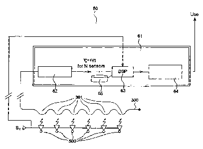
Figure 6 shows, as a block diagram, a diagram illustrating a
monitoring device according to an exemplary embodiment of the invention.
In a preferred exemplary embodiment of the invention, a monitoring
device 60 may comprise a processing unit 61. The processing unit 61 may
comprise an optoelectronic polling device 62 comprising for example an
emitter, not shown in the figure, emitting a laser beam in the optical fibre
300.
The optical fibre 300 comprises, in the example illustrated by the figure, a
plurality of sensor nodes 301 forming a Bragg network, the sensor nodes
each being placed close to microactuators 500. The polling device 62 may
also comprise a receiver not shown in the figure. The polling device 62 can
be connected to a signal processing device or "DSP" 63. Advantageously,
the DSP 63 is connected to a processing and diagnostic device 64 capable of
communicating with a central system for monitoring the system in which it is
incorporated, allowing, for example, a user to view alarms in the event of
malfunction. The DSP 63 notably makes it possible to establish a comparison
between the received signals, which are representative of the signatures of
the items of equipment placed close to the sensor nodes 301, and the
reference templates characteristic of their correct operation, in order to
generate a signal representative of the correct operation of the latter. The
reference templates can, for example, be stored in a database 65
communicating with the DSP 63.
Advantageously, the monitoring device 60 comprises means for
synchronizing the comparative analysis of the signals with the commands for
actuating the microactuators 500, these commands being represented by a
command signal Sc. The means for synchronizing the comparative analysis
of the signals can for example be implemented in the DSP 63. Specifically it
is possible to know in advance the microactuator for which the correct
operation must be monitored, since the microactuators are typically
commanded by a command device.
The embodiment of the comparative analysis between the stored
reference signature and the measured signature is of any known type, for
CA 02721500 2010-11-16
13
example a waveform template, or digital signal processing by Fourier
transform, or any other known method.
The embodiment described has the advantage of adding no
complexity to the monitored actuator system while introducing very simple
additional members: the optical fibre 300 and the processing unit 61. The
aforementioned first drawback of the prior art, that is to say the drawback
associated with increasing complexity, is thus resolved.
The embodiment described offers the advantage of a total price
reduced to that of the fibre sensor; the aforementioned second drawback of
the prior art, that is to say the drawback associated with cost, is thus
resolved.
The embodiment described also offers the advantage of a total space
requirement reduced to that of the fibre sensor; in particular, the outlying
space requirement close to the actuators is reduced to the fibre; the
aforementioned third drawback of the prior art, that is to say the drawback
associated with space requirement, is thus resolved. In the same manner,
the fourth drawback, that is to say the drawback associated with weight, is
resolved, in particular in the zone of the actuators,
The power consumption for the whole device according to the
invention is minimized by the time-multiplexed nature of the Bragg network
sensors; the aforementioned fifth drawback, that is to say the drawback
associated with power consumption, is thus resolved.
It should be noted that the only failure mode of each node of a
monitoring device 60 of an optical nature as described above is the total or
partial breakage of the optical fibre 300. Such a breakage has no functional
effect on the system into which the monitoring device 60 is incorporated.
Therefore, the penalty in reliability provided by the monitoring device 60 is
zero with respect to the system into which it is incorporated. The
aforementioned seventh drawback of the prior art, associated with the
penalty surrounding the reliability of the actuators, is thus resolved.
Moreover, the optical nature of the Bragg network sensors makes the
latter immune to thermal and electric environments and to impacts and
vibrations when the latter are appropriately maintained in the system into
which they are incorporated; that is to say, for example in the case of an
CA 02721500 2010-11-16
14
aircraft wing: because the latter are sunk into the structure of the wing in
an
appropriate manner. The aforementioned sixth drawback of the prior art,
associated with susceptibility, is thus resolved.