Note: Descriptions are shown in the official language in which they were submitted.
CA 02721987 2013-11-07
ROTOR FOR A PERMANENT MAGNET ELECTRIC MACHINE
Field of the invention
[0001] This disclosure relates to a permanent magnet electrical machine, such
as a motor
or generator, more specifically, to the field of interior permanent magnet
(IPM) electric
motors and the rotors for such machines.
[0002] The drive for energy efficiency and low cost motors in recent years has
led to
development of many types of electric motors and generators for various
applications.
Among the electric motor types, permanent magnet synchronous motors (PMSM) are
known to have high power density and efficiency. One of the more prevalent
types is often
referred to as an interior permanent magnet (IPM) motor, which is a specific
type of PMSM.
It is also known as a permanent magnet reluctance (PMR) motor because of its
hybrid
ability to produce reluctance torque as well as permanent magnet torque. A PMR
motor,
which includes a rotor having one or more permanent magnets embedded therein,
generates
a higher torque than a motor with magnets mounted on the surface of the rotor.
This
embedded structure produces an additional reluctance torque due to the
permanent magnets
positioned in the rotor core in such a way as to provide a variable reluctance
magnetic
circuit in the rotor core, also known as saliency.
[0003] During operation, each magnet embedded in the rotor core is subject to
centrifugal
force. In order to retain the magnets within the rotor core under the
centrifugal force,
narrow sections of rotor core material, called "bridges" or bridge regions,
are often retained
between the ends of a magnet pole and the outer periphery of the rotor core.
The centrifugal
force acting on the permanent magnets and the centrifugal force acting on the
rotor core are
concentrated in these bridges. For this reason, the radial widths of the
bridges are made
large enough to maintain the required mechanical strength. A difficulty in the
conventional
motor is that the bridge portions need to be made thick to meet the mechanical
strength
requirement at the expense of a higher flux leakage through the bridge
portions that leads to
a lower torque production. Conversely, thinner bridges lead to a reduction in
rotor strength,
thereby limiting the speed capability of the motor. This trade-off
relationship between
mechanical strength and magnetic flux leakage has limited the development of
higher-
speed, higher torque motors.
[0004] U.S. Patent 6,906,444 discloses various types of rotors configured to
address the
trade-off issue. Figs. 1 and 2 of the accompanying drawing are schematic
transverse cross
CA 02721987 2013-11-07
sectional diagrams of rotor cores described in the aforementioned patent. The
prior art rotor
core 11 in Fig. 1 includes a center pole section 15 having a plurality of
poles, wherein each
pole has three trapezoidal shaped magnet holes 12 and three permanent magnets,
i.e., a
center magnet 13a and two end-most magnets 13b, inserted in respective ones of
the magnet
insertion holes 12. The center pole section 15 forms bridges 16 disposed
between the outer
periphery of the center pole section 15 and the end-most magnets 13b. Between
neighboring
holes 12 there are disposed intermediate ribs 14 that prevent the centrifugal
force acting on
the permanent magnets 13 and center pole section 15 from being concentrated in
the bridges
16, thereby enhancing the rotational speed limit without increasing the radial
width of the
bridges 16. However, the multiple magnet insertion holes 12 and ribs 14
increase magnetic
flux leakage between neighboring poles and thus reduce torque production,
i.e., a higher
rotational speed may be obtained at the expense of torque reduction.
[0005] The prior art rotor core 21 shown in Fig. 1 includes U-shaped permanent
magnet
insertion holes 22 and permanent magnets 24 inserted in the holes. The rotor
core 21 also
includes an annular nonmagnetic ring 25 that covers the outer peripheral
portion of the rotor
core. The ring 25, which is formed of highly rigid nonmagnetic material, is
used in place of
the afore-mentioned bridges or in addition to the bridges. Because the annular
nonmagnetic
ring 25 is fitted over the outer peripheral portion of the rotor core 21, the
structure is able to
resist the breakage of the rotor due to the centrifugal force acting on the
magnets 24 and
center pole section 21 during operation. Also, the magnetic flux leakage from
the center
pole section 26 is reduced, thereby making it possible to obtain a high
magnetic flux density
in the center pole section 26. As the size of the permanent magnets 24 can be
made large
and the magnetic flux density produced in the center pole section 26 as well
as the saliency
in the rotor core 21 can increase, the overall torque can be increased.
However, the
disadvantage of incorporating the nonmagnetic ring 25 is that it significantly
increases the
manufacturing cost. Also, the gap between the rotor core 21 and stator (not
shown)
decreases and eddy current loss may increase if the ring 25 is metallic. Thus,
there is a need
for low cost electric machines having enhanced rotational speeds, power, and
torque
densities, without a ring such as shown in this prior art.
[0006] It would be desirable provide a permanent magnet electrical machine
which is
economical to produce and which reduces flux loss without weakening the rotor
and without
the use of intermediate ribs and annular rings.
2
CA 02721987 2013-11-07
Summary
[0007] In one embodiment, a rotor for a permanent magnet electric machine
includes: a
rotor core having a generally cylindrical shape with an outer circumferential
surface and a
rotational axis; a plurality of magnet insertion hole arrangements formed in
the rotor core
and arranged circumferentially at a preset angular interval about the
rotational axis, each
hole arrangement extending in a direction parallel to the rotational axis and
having a
radially inward side, a radially outward side, and two ends that are
respectively spaced apart
from the circumferential surface by respective bridge regions formed by the
rotor core, the
material of the bridge regions being metallurgically transformed to possess
greater magnetic
reluctance than the material of adjacent portions of the rotor core.
[0008] Also disclosed is a method for making the rotor in which the
metallurgical
transforming of the bridge region material is performed by changing the grain
structure of
the material. A preferred technique for achieving that change is by heating
the material to at
least its Curie temperature, e.g., by laser heating.
Brief Description of the Drawings
[0009] Fig. I is a fragmentary view of a first prior art permanent magnet
rotor.
[0010] Fig. 2 is a fragmentary view of a second prior art permanent magnet
rotor.
[0011] Fig. 3 is a longitudinal sectional view of a prior art permanent magnet
electric
machine.
[0012] Fig. 4 is a fragmentary view of a first permanent magnet rotor
according to the
invention, being used in the machine of Fig. 3.
[0013] Fig. 5 is a fragmentary view of a second permanent magnet rotor
according to the
invention.
[0014] Fig. 6 is a fragmentary view of a third permanent magnet rotor
according to the
invention.
[0015] Fig. 7 is a fragmentary view of a fourth permanent magnet rotor
according to the
invention.
[0016] Fig. 8 is a fragmentary view of a fifth permanent magnet rotor
according to the
invention.
[0017] Fig. 9 is a fragmentary view of a sixth permanent magnet rotor
according to the
invention.
3
CA 02721987 2013-11-07
Detailed Description of Preferred Embodiments
[0018] As explained in detail below, bridge regions of a permanent magnet
rotor, which
retain the permanent magnets against centrifugal force, are treated or
manipulated so as to
reduce their magnetic permeability, i.e., to increase their magnetic
reluctance, whereby the
magnetic permeability of the bridge regions is less than that of portions of
the rotor core
situated adjacent the bridge regions. That produces advantages including
increasing the
saliency of the rotor and the reluctance torque produced by the motor,
minimizing flux
leakage to the opposite magnet pole within the rotor core to allow more magnet
flux to link
the stator, and strengthening the bridge regions to allow the motor to operate
at higher
speeds.
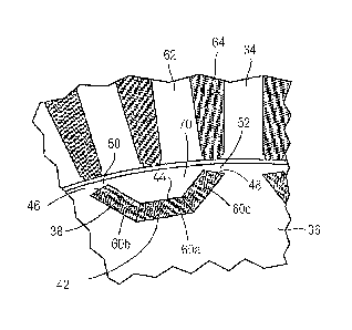
[0019] Depicted in Figs. 3 and 4 is a permanent embedded magnet-type electric
machine
such as an electric motor 30, comprising a housing 32 in which is disposed a
conventional
stator 34 surrounding a rotor core 36 that is rotatably mounted in a
conventional manner.
Formed in the rotor core are magnet insertion holes 38, preferably of a U-
shape which is
concave with respect to a circumferential surface of the rotor core. Each hole
38 extends in
a direction parallel to the rotational axis A of the rotor and having a
generally concave cross
sectional shape relative to the circumferential surface 40 of the rotor core.
Each hole has a
radially inward side 42, a radially outward side 44 and two ends 46, 48 that
are spaced apart
from the circumferential surface 40 by respective bridge regions 50, 52 formed
by the rotor
core 36. Permanent magnets, i.e., a center magnet 60a and two outer magnets
60b and 60c,
are inserted in each of the holes.
[0020] The rotor core (and thus the bridge regions) can be formed of various
metals, such
as silicon steel (SiFe), carbon steel, nickel iron (NiFe) and cobalt iron
(CoFe), for example.
[0021] The stator includes teeth 62 formed along the inner periphery thereof
at a preset
angular interval and windings or coils 64 wound around the teeth. The coils
may be, for
instance, three-phase windings, if a three-phase alternating current is
allowed to flow
through the coils. The rotor core is caused to rotate by a permanent magnetic
field torque
due to the interaction between the current flowing through the coils and the
magnetic flux of
the permanent magnets. Also, each permanent magnet tends to align itself in
the minimum
reluctance position relative to the magnetic field generated by the current
flowing through
the coils, thereby generating the reluctance torque that also turns the rotor
core with respect
to the stator core.
4
CA 02721987 2013-11-07
[0022] The bridge regions, which retain the magnets against centrifugal force
generated
during motor operation, can be of various shapes, including a constant width
shape or a
varying width shape as shown in Fig. 4 and described in U.S. Patent No.
7,598,645. The
cross sections of the magnets shown in Fig. 4 are designed such that one
magnet makes tight
contact with neighboring permanent magnet(s) in the hole during operation,
i.e., one side
surface of the center magnet 60a is in contact or would be forced to be in
contact with a side
surface of the left outer magnet 60b under excitation from centrifugal or
radial force during
operation. Likewise, the other side surface of the center magnet 60a is in
contact or would
be forced in contact with a side surface of the right outer magnet 60c under
excitation from
centrifugal force. The centrifugal force acting on the permanent magnets
during operation
is then transmitted through the permanent magnets to appropriate ones of the
bridge regions
50, 52.
[0023] In accordance with the invention, the amount of flux loss through the
bridge
regions 50, 52, is reduced by treating or manipulating the material of the
bridge regions so
as to reduce the magnetic permeability thereof, i.e., to increase their
magnetic reluctance,
whereby the magnetic permeability of the bridge regions is less than that of
portions of the
rotor core situated adjacent the bridge regions. Such local reluctance
enhancement (LRE)
results in a number of benefits. First, it increases the saliency of the rotor
and therefore
increases the reluctance torque produced by the motor. Second, it minimizes
flux leakage to
other poles within the rotor core, allowing more magnet flux to link the
stator, thereby
increasing the torque produced by the permanent magnets. Third, it may
strengthen the
bridge regions which will allow the motor to operate at higher speeds. Those
benefits,
resulting in additional torque production, will translate to less material
needed in the motor
to produce the same torque and power. Therefore, less cost will be incurred in
motor
production.
100241 The localized manipulation of the material properties in the bridge
regions 50, 52
may be accomplished in a number of different ways in order to change the grain
structure of
the bridge regions. For example, the bridge regions can be locally heated to
at least the
Curie temperature of the rotor core material. (The Curie temperature of SiFe
is 1400-1450
and that of CoFe is 15751625 ). Such heating will change the grain structure
of the
material and thus reduce, possibly eliminating, the magnetic permeability of
the material. It
is apparent that this goal is achievable because certain phases of ferrous
materials with
CA 02721987 2013-11-07
modified or randomized grain structures have been shown to be almost
completely non-
magnetic or exhibit high magnetic reluctance close to that of air.
[0025] The local heating would preferably be achieved by use of a laser. In
laser heat
treating, energy is rapidly transmitted to the material in order to effect a
metallurgical
transformation. Both CO2 and Nd:YAG continuous wave lasers would be suitable
for this
purpose.
[0026] Other techniques for changing the grain structure of the bridge
material include,
but are not necessarily limited to: quenching or various methods of controlled
cooling of the
bridge regions, cold working (also called work hardening) by impacting the
bridge regions,
hot working (deformation of the material at elevated temperatures) of the
bridge regions, or
combinations of the above techniques.
[0027] Due to the resulting increased reluctance in the bridge regions, the
magnetic flux
leakage from the center pole section 70 to neighboring poles is reduced by
decreasing the
ability of the bridge regions to conduct flux, thereby making it possible to
obtain a higher
magnetic flux density in the center pole section 70. Moreover, there is no
limit on the
thickness with which the bridge regions can be made in order to make them able
to resist
rotor breakage under the action of centrifugal forces acting on the magnets
during operation,
thereby enabling rotor speed to be increased. Also, the size of the permanent
magnets can
be made larger, resulting in an even greater increase in magnetic flux density
produced in
the center pole section 70. The increased magnetic flux density in the center
pole section,
combined with the fact that the saliency in the rotor core 36 will be
increased, means that
the overall torque of the motor can be increased.
[0028] In addition, the rotor core 31 requires no retention ring covering the
outer
peripheral portion of the rotor core as proposed in the prior art. The
elimination of such a
nonmagnetic retention ring reduces the manufacturing cost, and allows the air
gap between
the rotor core 36 and stator 34 to be optimized to improve performance. It
also improves
the performance of machines which rely on magnetic saturation and small bridge
regions to
minimize flux linkage. Because of local reluctance enhancement in the bridge
regions, the
bridge regions can be larger, providing for more strength and higher speed.
Additionally,
for bridge regions of a given size, local reluctance enhancement will provide
higher torque.
Thus, this invention provides a means for low cost motors with enhanced
rotational speeds,
power, and torque densities.
6
CA 02721987 2013-11-07
100291 As noted above, the increased reluctance in the bridge regions will
improve
generated torque by increasing the saliency of the rotor and reducing PM
magnet flux
leakage from the primary path through the stator. The same process that
produces the
increased reluctance is also expected to increase mechanical strength of the
bridge regions.
Such increased strength may allow the bridge thickness to be made smaller than
would
otherwise be the case, further increasing the rotor' saliency and reducing the
flux leakage.
[0030] The above-described local reluctance enhancement of the rotor's bridge
regions is
applicable to a variety of IPM rotor geometry employing bridges, which retain
magnets and
contain the flux leakage between magnet poles, e.g., as shown in Figs. 5-8,
respectively. In
Fig. 5, a rotor core 80 possesses generally concave V-shaped permanent magnet
insertion
holes 82, two trapezoidal-shaped permanent magnets 84 inserted in the holes,
and bridge
regions 86. In Fig. 6, a rotor core 90 possesses generally concave V-shaped
arrangement of
permanent magnet insertion holes 92, two rectangular permanent magnets 94
inserted in the
holes, and bridge regions 96. In Fig. 7, a rotor core 100 possesses a
generally concave U-
shaped permanent magnet insertion hole 102, a correspondingly U-shaped
permanent
magnet 104 inserted in the hole, and bridge regions 106. In Fig. 9, a
generally concave U-
shaped permanent magnet insertion hole 112 receives, two curve-shaped
permanent
magnets 114, and bridge regions 116. The localized treatment or manipulation
of the
material properties in the bridge regions 86, 96, 106 and 116 of Figs. 5-8 may
be
accomplished using one or more of the techniques described above.
[0031] It is also possible to employ a rotor wherein each hole arrangement
comprises
multiple holes separated from one another by ribs, as shown in Fig. 1, wherein
the ribs 14
and the bridge regions 16 are metalurgically transformed to reduce the
magnetic
permeability thereof.
[0032] It should be apparent to those of ordinary skill in the art that the
rotor core may
have any suitable numbers of magnet-receiving holes, and can be used in any
suitable type
of permanent magnet motor.
[0033] While the invention has been described in detail with reference to
specific
embodiments thereof, it will be apparent to those skilled in the art that
various changes and
modifications can be made, and equivalents employed, without departing from
the scope of
the appended claims.
7
CA 02721987 2013-11-07
100341 The magnet need not be curved. It could be a flat magnet 124 as shown
in Fig. 8,
which forms bridge regions 126.
8