Note: Descriptions are shown in the official language in which they were submitted.
CA 02722080 2010-10-20
WO 2009/133460 PCT/IB2009/005597
1
Profiled gasket for lined piping
The present invention relates to lined piping systems, and more particularly
to a
profiled gasket for flanged joints in a lined piping system.
BACKGROUND OF THE INVENTION
Internally lined piping systems are used in numerous commercial applications
by the
pharmaceutical, chemical, petroleum, food, and other industries for
transporting and
processing products and chemicals in dry, liquid, or gaseous forms and
combinations
thereof. Lined piping generally includes two components: (1) a tubular
metallic
outer jacket or pipe which provides strength for pressure retention and
support, and
(2) an inner liner applied or affixed thereto. The liners are typically made
of a
chemically and/or abrasion resistant non-metallic material. The choice of
liner
materials depends on the intended use, such as to prevent contamination of the
product by the outer pipe or conversely to prevent the outer pipe from
corrosion,
abrasion, or chemical attack caused by the transported media. Some common
liner
materials used include without limitation Polytetrafluoroethylene (PTFE),
Polypropylene (PP), Perfluoroalkoxy (PFA), Polyvinylidene Difluoride (PVDF),
Polyvinylidene Chloride (PVDC), Ethylenetetrafluoroethylene (ETFE),
elastomerics,
glass, ceramic glass, and others. Accordingly, various plastic-lined and glass-
lined
piping is commercially available and used in many applications.
Flanged connections may be used for joining multiple sections of lined pipe to
create
various piping system configurations and/or to connect the lined piping to
various
types of in-line components such as valves, pumps, process tanks, mixers, etc.
One
common arrangement of a flanged piping assembly for a lined piping system is
shown in U.S. Patent Nos. 4,313,625 and 4,643,457, both of which are
incorporated
herein by reference in their entireties. The inner pipe liner is gradually
flared at the
end with respect to the longitudinal axis of the piping and protrudes radially
outward
beyond the terminal end of the pipe to at least partially cover and extend
across a
CA 02722080 2010-10-20
WO 2009/133460 PCT/IB2009/005597
2
portion of the end face of the radially-extending flange. In some embodiments,
such
as in the case of plastic-lined pipe, the flared liner may be made by heating
an
exposed end of the liner followed by flaring or molding the liner over against
the end
face of the flange. A pressure seal is formed by compression at the piping
joint by
the mating inner liners of adjoining sections of piping when the flanges are
coupled
together by bolting, clamping, or other similar compression assembly means.
Accordingly, this design eliminates the need for any additional gaskets or
sealing
members since the abutting flared or formed liner portions creates the seal
and
prevents the flowing material from contacting the metal outer pipe at the
joints.
As more clearly shown herein in FIG. 1, however, each of mating flanges in the
foregoing known joint design has a smooth, gradual inner liner radius R formed
where the liner is flared outward and transitions between the inside axial
portion of
the pipe and end face of the flange. The radius defines convex, rounded end
surface
R that forms a smooth transition in contrast to sharp 90-degree liner end
edges as
found in other known designs such as shown in U.S. Patent No. 5,876,070, which
is
incorporated herein by reference in its entirety. Accordingly, when two lined
flanges
with smooth convex edges are coupled together, this creates a V-shaped annular
groove or gap G between flanges at the adjoining sections of inner liners. The
gap G
results in a "dead-zone" where flowing material or product may collect in the
piping
system such as, for example, in pneumatic or vacuum material transport,
liquid,
liquid slurry, or other type of fluid piping systems. In pharmaceutical final
product
and/or food-grade lined piping system applications that must meet rigid
sanitary
standards, such product accumulation is undesirable and may'lead to eventual
contamination of the product over time. This requires periodic disassembly of
the
flanged piping joints to remove the accumulated debris or product, which is
time
consuming, increases maintenance expenses, and adds to final product costs.
Although in some applications, food grade and pharmaceutical grade "sanitary-
type"
CA 02722080 2010-10-20
WO 2009/133460 PCT/IB2009/005597
3
piping systems employing special clamped fittings having zero dead-space may
be
used to eliminate dead-zones (such as Tri-Clover fittings available from Alfa
Laval
of Richmond, Virginia), these systems are more expensive than a lined flange
joint
system.
An improved lined piping system flange joint with less, and preferably zero,
dead-
space is desirable.
SUMMARY OF INVENTION
The present invention provides a specially profiled gasket that reduces the
foregoing
problems in lined piping systems utilizing flanged joints. In one embodiment,
the
gasket is configured and adapted to minimize or eliminate the dead space that
would
otherwise form at the flange joints between the liners. This embodiment
prevents the
accumulation of debris that might otherwise lead to contamination of the
flowing
product. Advantageously, this embodiment is intended to greatly reduce or
preferably eliminate the need for periodic disassembly of the piping systems
to
remove the accumulated debris. Furthermore, this embodiment is intended to
facilitate the use of a more cost-effective flanged lined piping system rather
than
conventional sanitary-grade systems having zero dead-space clamped joints.
According to one embodiment of the present invention, a lined piping assembly
defining an interior flow path and a longitudinal axis includes: a first
piping section
terminated with a first flange and including an inner liner having a first
flared portion
extending radially outward along an end face of the first flange, the first
flared
portion defining a first convex liner end surface; a second piping section
terminated
with a second flange and including an inner liner having a second flared
portion
extending radially outward along an end face of the second flange, the second
flared
CA 02722080 2010-10-20
WO 2009/133460 PCT/IB2009/005597
4
portion defining a second convex liner end surface; the first and second
flared
portions of the liners forming a gap therebetween having a narrow portion
distal to
the interior flow path of the piping assembly and a wider portion proximal to
the
interior flow path of the piping assembly; and a profiled gasket disposed
between the
first and second flared portions and having a configuration that fills the
gap. By
filling the gap, the profiled gasket serves to prevent accumulation of
material at the
juncture of the first and second flanges.
According to another embodiment of the present invention, a lined piping
assembly
defining an interior flow path and a longitudinal axis includes: a first
piping section
terminated with a first flange and including an inner liner having an axial
portion and
a radial portion extending radially outward along an end face of the first
flange, the
liner having a first rounded convex end surface formed at a transition between
the
axial and radial portions of the liner; a second piping section terminated
with a
second flange and including an inner liner having an axial portion and a
radial
portion extending radially outward along an end face of the second flange, the
liner
of the second piping section having a second rounded convex end surface formed
at a
transition between the axial and radial portions of the liner, the first and
second
rounded convex end surfaces defining an annular V-shaped gap therebetween
opening into the interior flow path of the piping assembly when the first and
second
flanges are positioned proximate to each other; and a profiled gasket disposed
between the first and second flanges, the gasket having a pair of concave side
surfaces facing in opposing directions, each side surface being configured to
engage
one of the first and second rounded convex end surfaces for filling the
annular V-
shaped gap when the first and second flanges are drawn together.
According to another embodiment of the present invention, a lined piping
assembly
defining an interior flow path and a longitudinal axis includes: a first
piping section
CA 02722080 2010-10-20
WO 2009/133460 PCT/IB2009/005597
terminated with a first flange and including an inner liner having an axial
portion and
a radial portion extending radially outward along an end face of the first
flange, the
liner having a first rounded convex end surface formed at a transition between
the
axial and radial portions of the liner; a second piping section terminated
with a
second flange and including an inner liner having an axial portion and a
radial
portion extending radially outward along an end face of the second flange, the
liner
of the second piping section having a second rounded convex end surface formed
at a
transition between the axial and radial portions of the liner; and a gasket
including a
generally V-shaped portion when viewed in cross-sectional profile for
positioning
along the interior flow path, the gasket having a width that gradually narrows
in a
radial direction away from the flow'path, the gasket being engaged between the
first
and second convex end surfaces of the liners for forming a pressure seal when
the
first and second flanges are drawn together.
According to yet another embodiment of the present invention, a lined piping
assembly defining an interior flow path and a longitudinal axis includes: a
first
piping section including a first flange and an inner liner having a first
flared portion
extending radially outward from an end of the first piping section, the first
flared
portion defining a first convex liner end surface; a second piping section
including a
second flange and an inner liner having a second flared portion extending
radially
outward from an end of the second piping section, the second flared portion
defining
a second convex liner end surface; the first and second flared portions of the
liners
being abutted and forming a V-shaped gap therebetween with the wider portion
of
the V-shaped gap located proximal to the interior flow path of the piping
assembly;
and a profiled gasket disposed between the first and second flared portions of
the
liners and having a configuration that fills the V-shaped gap when the first
and
second flared portions are drawn together to prevent accumulation of material
in the
gap. In one embodiment, the first and second flared portions of the liners
each
CA 02722080 2010-10-20
WO 2009/133460 PCT/IB2009/005597
6
extend radially outward along the face of the first and second flanges,
respectively.
In another embodiment, the first and second flared portions of the liners each
extend
radially outward along a radially flared portion of the end of the first and
second
piping sections, respectively, wherein the first and second piping sections
have
lapped pipe ends. In one embodiment, the first and second flanges may be loose-
fitting lap joint rotating flanges.
In another embodiment, the present invention provides a profiled annular
gasket
adapted for flanged piping joints used in a lined piping system defining an
interior
flow path, which gasket includes: an annular inner portion for positioning
along an
interior flow path,of a piping system, the annular inner portion having an
axial width
that gradually narrows in a radial direction away from the flow path; an
annular outer
portion adjacent to the inner portion; a pair of sides extending between the
annular
inner portion and the annular outer portion; and a recessed annular side
surface
disposed in each side of the gasket, each side surface being adapted and
configured
to engage a convex end surface of an inner liner of a pipe section.
Preferably, the
gasket is engageable between an opposing pair of the end surfaces defined by
inner
liners of two abutting pipe sections at a piping joint. The gasket forms a
pressure
seal when the piping sections are drawn together. In one embodiment, the
piping
joint is a flanged joint.
BRIEF DESCRIPTION OF THE DRAWINGS
The features of several embodiments of the present invention will be described
with
reference to the following drawings where like elements are labeled similarly,
and in
which:
CA 02722080 2010-10-20
WO 2009/133460 PCT/IB2009/005597
7
FIG. 1 is a partial cross-sectional side view of a prior art flanged joint for
a lined
piping system;
FIG. 2 is a magnified view of a portion of FIG. 1;
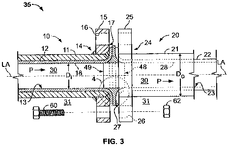
FIG. 3 is a partial cross-sectional side view of a first embodiment of a
gasket and
flanged joint for a lined piping system according to the present invention;
FIG. 4 is a magnified view of a portion of FIG. 3;
FIG. 5 is a partial cross-sectional side view of a second embodiment of a
gasket and
flanged joint for a lined piping system according to the present invention;
FIG. 6 is a magnified view of a portion of FIG. 5;
FIG. 7 is a partial cross-sectional side view of the gasket of FIGS. 3 and 4
according
to the present invention;
FIG. 8 is a partial cross-sectional perspective view of the gasket of FIGS. 3
and 4
according to the present invention;
FIG. 9 is a detailed partial cross-sectional side view of a third embodiment
of a
gasket and flanged joint for a lined piping system according to the present
invention;
and
FIG. 10 is a partial cross-sectional side view of an alternative embodiment of
a
flanged joint for a lined piping system in the form of a pipe lap joint and
gasket of
FIGS. 3 and 4 according to the present invention.
CA 02722080 2010-10-20
WO 2009/133460 PCT/IB2009/005597
8
All drawings are schematic and not drawn to scale.
DETAILED DESCRIPTION OF THE INVENTION
In the description of embodiments of the present invention disclosed herein,
any
reference to direction or orientation is merely intended for convenience of
description and is not intended in any way to limit the scope of the present
invention.
Moreover, although the features and benefits of the invention are illustrated
by
reference to particular embodiments, the invention expressly should not be
limited to
such embodiments illustrating some possible but non-limiting combination of
features that may be provided alone or in other combinations of features.
FIGS. 3 and 4 show a first embodiment of a profiled gasket that is configured
to fill
the gap or "dead zone" (see, e.g. FIG. 2) that may otherwise be created at
flanged
joints in a lined piping system. Lined pipe useable with this profiled gasket
may be,
for example, ResistoflexTM brand piping available from Crane Resistoflex
Corporation of Marion, North Carolina.
Referring to FIGS. 3 and 4, one embodiment of a lined piping assembly is shown
in
the form of a flanged joint 35 that couples together two adjoining piping
sections 10,
20, each section having an inner liner'(12, 22). The flanged joint is coupled
by
conventional flange bolting including a plurality of bolts 60 and nuts 62.
Piping
sections 10 and 20 collectively define an interior 30 and an exterior 31 of
the coupled
piping assembly. Pipe section 10 includes an outer jacket or pipe 11 and an
inner
liner 12 having an inner surface 13 defining a flow path P therethrough. Pipe
section
20 similarly includes an outer jacket or pipe 21 and an inner liner 22 having
an inner
surface 23 defining a flow path P therethrough. Although flow path P is shown
in a
direction from left to right, it will be appreciated that flow path P may be
in an
CA 02722080 2010-10-20
WO 2009/133460 PCT/IB2009/005597
9
opposite direction and in any orientation including horizontal, vertical, or
at an angle
therebetween. In some embodiments, either one or both of pipe sections 10, 20
may
be any type of pipe section including a nipple or similar connection disposed
on
various in-line piping system components and equipment such as, without
limitation,
fittings (e.g. elbows, tees, etc.), valves, pumps, strainers, process tanks,
heaters, etc.
adapted to connect to a piping system. Accordingly, the invention is not
limited in
use to piping-to-piping joints alone.
Pipe sections 10, 20 each define a longitudinal axis "LA" extending along the
flow
path P which is defined and referred to herein as the axial direction. A
radial
direction is defined as being transverse or perpendicular to the longitudinal
axis LA
and the term as used herein is given its conventional meaning in the art. Each
pipe
section 10, 20 has an inside diameter Di measured between diametrically
opposed
inner surfaces 13, 23 of liners 18, 28, respectively. Each pipe section 10, 20
further
has an outside diameter Do measured between diameter opposed exterior surfaces
of
outer pipes 11, 21.
With continuing reference to FIGS. 3 and 4, outer pipes 11, 21 may be made of
any
suitable material commonly used in commercially-available lined piping
systems. In
some embodiments, outer pipes 11, 21 may be, for example, metal, such as
without
limitation steel, aluminum, copper, brass, cast iron, or other suitable
metals. Inner
liners 12, 22 may be, for example, made of any suitable materials commonly
used in
conventional lined piping systems, such as without limitation PTFE, PP, PFA,
PVDF, elastomerics, rubbers, and others. In a preferred embodiment, inner
liners 12,
22 are made of a pharmaceutical-grade or food-grade material of the type used
in
sanitary piping systems.
CA 02722080 2010-10-20
WO 2009/133460 PCT/IB2009/005597
With continuing reference to FIGS. 3 and 4, pipe sections 10, 20 each have
terminal
ends 14, 24 that are terminated in one embodiment with radial flanges 15, 25
extending in a radial direction transverse to longitudinal axis LA. Flanges
15, 25
each define respectively a radial end face 17, 27 for mating to an opposing
flange.
Flanges 15, 25 may be formed as an integral part of outer pipes It, 21, or as
separate
components attached to outer pipes 11, 21 by welding, threading, or other
suitable
conventional means used in the art, or loose. In one embodiment, flanges 15,
25 may
be welded to outer pipes 11, 21.
It will therefore be appreciated that the flanges may be of any type suitable
for use
with lined piping systems wherein the piping liners are abutted to form a
joint,
including but not limited to loose lap joint/rotating flanges, slip-on welded
flanges,
socket weld flanges, weld-neck flanges, threaded flanges, etc. Accordingly,
the
invention is not limited to, or for use in, any particular type of flange.
In one embodiment, with reference to FIG. 3, flanges 15, 25 each include a
plurality
of conventional circumferentially-spaced bolting holes 16, 26 configured to
receive
flange bolts 60 used with nuts 62 for coupling the two flanges together and
drawing
piping sections 10 and 20 together. However, other suitable means such as,
without
limitation, clamping may be used to couple the flanges together.
With continuing reference to FIGS. 3 and 4, in one embodiment, inner liner 12
has a
flared portion that extends radially outward from the interior 30 of pipe
section 10 in
a direction transverse to longitudinal axis LA, and more preferably along at
least a
portion of radial end face 17 of flange 15 as shown to form part of a pressure
seal at
the flange joint. In one embodiment, accordingly, inner liner 12 is a
continuous
element that includes a flared radial flange liner portion 19 (see FIG. 4) and
a
contiguous axial liner portion 18 extending along longitudinal axis LA.
Similarly, in
CA 02722080 2010-10-20
WO 2009/133460 PCT/IB2009/005597
11
one embodiment, inner liner 22 of pipe section 20 also preferably has a flared
portion
that extends radially outward along at least a portion of radial end face 27
of flange
25 in the same manner to be coupled with opposing end face 17 of flange 15, as
further described herein. Inner liner 22 therefore may also be a continuous
element
that includes a flared radial liner portion 29 (see FIG. 4) and a contiguous
axial liner
portion 28 extending along longitudinal axis LA. In one embodiment, inner
liners
12, 22 are permanently adhered to their respective outer pipes 11, 21 and
flanges 15,
25.
Referring to FIG. 4, liners 12 and 22 define a radial, generally convex liner
end
surface RI formed at a transition between radial liner portions 19, 29 and
axial liner
portions 18, 28 (shown in FIG. 3), respectively. Convex liner end surface R1
may be
rounded and smooth in cross-sectional profile in some embodiments as shown
(FIGS. 3-6). In other embodiments (e,g, as shown in FIG. 9), convex liner end
surface R3 may be chamfered or angled in cross-sectional profile. Since the
convex
liner end surface shape of the applied liner will be generally dictated by the
shape of
the underlying pipe end preparation used (as shown, e.g., in FIGS. 4 and 9),
numerous variations are possible in the liner end surface shape. Accordingly,
the
invention is not limited to gaskets fitting any particular liner end surface
shape.
With continuing reference to the embodiment shown in FIGS. 3 and 4, an annular
and generally triangular (or V-shaped) groove or gap G is formed between
flanges 15
and 25 when pipe sections 10, 20 are positioned proximate to each other as
shown
(see also FIG. 2). Gap G extends circumferentially along the inner surfaces 13
and
23 of inner liners 12, 22 of pipe sections 10 and 20, respectively. The widest
portion
of gap G lies closest to inner surfaces 13, 23 proximal to the flow path P and
the
narrowest portion of gap G lies more distal to and radially outward from the
flow
path P than the wider portion at joint 35. It will be appreciated that gap G
may not
CA 02722080 2010-10-20
WO 2009/133460 PCT/IB2009/005597
12
be perfectly V-shaped, but this term is used herein with the understanding
that gap G
will generally approximate a V-shape in cross-section. Depending on the
manufacturing process, and the type of material or product being transported
in the
piping system, debris may accumulate in gap G, and this accumulation may be
undesirable, particularly for a lined piping system.
With continuing reference to FIGS. 3 and 4, gap G is filled in one embodiment
by
inclusion of a profiled annular gasket 40 having a complementary V-shaped
portion
which extends circumferentially in gap G. Preferably, gasket 40 is continuous
in
structure forming an unbroken ring-shaped element that is configured and
adapted to
fill gap G. With additional reference to FIGS. 7 and 8, gasket 40 includes an
inner
portion 41 disposed in contact with the two generally convex liner end
surfaces R1
on inner surfaces 13 and 23 of inner liners 12 and 22, respectively, when
installed.
In one embodiment, inner portion 41 of gasket 40 has a generally triangular or
V
shape, which progressively narrows or tapers in width in a radial direction
away from
the interior 30 to the exterior 31 of the piping, wherein the gasket 40 is
dimensioned
and toleranced to approximately "match" or align with the adjacent surfaces.
Inner portion 41 of gasket 40 further defines an inner axial gasket face 43
which is in
direct communication with the flow path P and exposed to the material or media
being transported in piping sections 10, 20. Accordingly, gasket face 43 forms
part
of the flow path P in the interior 30 of piping sections 10, 20 when installed
between
flanges 15 and 25. In one embodiment, inner gasket face 43 has a substantially
flat
surface which preferably aligns with and is parallel to axial liner portions
18, 28 as
shown. In this embodiment, the inside diameter of gasket 40 measured between
diametrically opposed sections of gasket at face 43 is approximately equal to
the
inside diameter Di of piping sections 10 and 20 measured between diametrically
opposed inner surfaces 13, 23 of liners 18, 28 to form a relatively smooth
flow path P
CA 02722080 2010-10-20
WO 2009/133460 PCT/IB2009/005597
13
without gaps between the flanges. In other embodiments as shown in FIGS. 5 and
6,
inner gasket face 43 may have a convex shaped surface in profile to produce a
venturi effect for increasing flow velocity and clean sealing of the mating
area
between the gasket and interior 30 of piping sections 10, 20. Accordingly,
when a
convex shaped gasket face 43 is provided, the inside diameter of gasket 40
will be
slightly less than the inside diameter Di of piping sections 10 and 20.
Gasket 40 further includes an outer portion 42 that is disposed opposite inner
portion
41 as shown in FIGS. 4, 6, 7, and 9. In one embodiment, outer portion 42 may
be
generally rectangular in cross-sectional profile and may be defined as
beginning
where the tapered sides 46, 47 of inner portion 41 end and become generally
parallel
to each other. Outer portion 42 is positioned toward the exterior 31 of piping
sections 10, 20 at flanges 15, 25, and does not have portions in contact with
flow
path P unlike inner portion 41. Preferably, outer portion 42 extends outward
to a
radial distance at least equal to or greater than flared radial liner portions
19, 29 so as
to securely compress and retain gasket 40 between the coupled flanges 15, 25
when
drawn together.
Referring to FIGS. 4 and 7, inner portion 41 of gasket 40 has an axial width
Wi and
outer portion 42 has an axial width Wo. Preferably, the maximum width of Wi is
larger than the maximum width of Wo to correspond with the general V-shaped
configuration of gap G. Accordingly, in a preferred embodiment, gasket 40
becomes
progressively narrower in width in a radially outward direction from the
interior 30
of piping sections 10, 20 to the exterior 31 of the same. The widest portion
of gasket
40 is therefore disposed closest to inner surfaces 13 and 23 of pipe sections
10 and
20 adjacent to the flow path P.
CA 02722080 2010-10-20
WO 2009/133460 PCT/IB2009/005597
14
With continuing reference to FIGS. 4 and 7, gasket 40 further includes a pair
of
axially spaced-apart radial sides 46 and 47 formed along inner portion 41 and
outer
portion 42. In one embodiment, sides 46, 47 converge towards each other along
inner portion 41 and are disposed in parallel relation to each other along
outer
portion 42 as shown in FIG. 7. Sides 46 and 47 define a pair of spaced-apart
annular
sealing edges 48, 49 that extend circumferentially along the inner diameter of
pipe
sections 10, 20 when the gasket 40 is mounted in flanged joint 35. As shown,
for
example, in FIG. 4, sealing edges 48, 49 engage and mate with inner surfaces
13, 23
of liners 12, 22, respectively, on opposite sides of gasket 40 to form a seal
in the
interior 30 of pipe sections 10, 20 and to provide a smooth transition between
inner
surfaces 13, 23 at the joint. Accordingly, in one embodiment, sealing edges
48, 49
define annular line contact between gasket 40 and inner surfaces 13, 23 on the
interior 30 of the piping to seal flanged joint 35. The adapted detailed
design and
configuration of any particular gasket 40 would preferably be dimensioned and
toleranced to appropriately "match" the adjacent surfaces.
In a further embodiment, with reference to FIGS. 3-4 and 7-8, sides 46, 47 of
gasket
40 each further define a respective annular axial side surface 44, 45 that is
configured
and adapted to receive and engage the two generally convex liner end surfaces
R1 on
inner liners 12, 22. In one embodiment, side surfaces 44 and 45 preferably
face in
opposite axial directions. In one embodiment, side surfaces 44, 45 are
preferably
formed as recesses in each side 46, 47 of gasket 40, and more preferably may
be
generally concave in shape as shown. Side surfaces 44, 45 have a radius of
curvature
R2 selected to complement and approximate the shape or radius of the mating
liner
end surfaces R1 of each radial flange liner portion 19 and 29. It will be
appreciated
by those skilled in the art that the radius of curvature of R2 of side
surfaces 44, 45
need not exactly match the radius or shape of end surfaces RI of the flange
liners 12,
22 since the gasket 40 and/or the liners may be compressible and deformable to
a
CA 02722080 2010-10-20
WO 2009/133460 PCT/IB2009/005597
certain degree depending on the types of materials selected for the gasket and
liners.
In other embodiments to be further described herein with reference to FIG. 9,
side
surfaces 44, 45 may have other suitable cross-sectional shapes such as angular-
shaped recesses to complement the shapes of the mating convex liner end
surfaces.
Thus the invention is not limited by the shape of side surfaces 44, 45 as
described by
the exemplary embodiments set forth herein.
Profiled gasket 40 may be made of any suitable metallic or non-metallic
material
depending on the requirements of the intended application. In a preferred
embodiment, gasket 40 is made of a pharmaceutical-grade or food-grade
compatible
material suitable for use where a chemically resistant lined process piping
system is
needed. In some embodiments, gasket 40 may be made of a relatively resilient
and
deformable material such as PTFE, enhanced PTFE, reinforced PTFE or other
suitable materials compatible with pharmaceutical-grade or food-grade sanitary
process piping systems. In other embodiments, gasket 40 may be made of a
relatively hard or minimally deformable non-metallic material such as carbon
fiber,
para-aramid synthetic fiber such as KevlarTM available from E. 1. du Pont de
Nemours and Company of Wilmington, Delaware, polyamide-imide such as Torlon
available from Solvay Advanced Polymers of Alpharetta, Georgia, composites, or
similar. In yet other embodiments, gasket 40 may be made of a hard metallic
material such as wrought corrosion-resistant nickel-molybdenum-chromium alloy
such as Nikelvac HC-276TH, pharmaceutical grade stainless steels, and other
similar
metals. In other embodiments, gasket 40 may be made of any non-metallic or
metallic material for non-sanitary grade process piping. Accordingly, it will
be
appreciated that the invention is not limited to any particular material for
gasket 40.
It is well within the ambit of those skilled in the art to select a material
appropriate
for the intended application.
CA 02722080 2010-10-20
WO 2009/133460 PCT/IB2009/005597
16
Gasket 40 may be made by any suitable commercial manufacturing process
typically
used to make gaskets; the particular process selected for manufacture being
dependent upon the type of material selected for the gasket. Gasket 40 may
therefore
be made by techniques including, without limitation, molding, casting,
forging,
machining, and combinations thereof or other suitable methods.
Figure 9 shows an alternative embodiment of a flanged joint 50 for use in a
piping
assembly. In FIG. 9, a common angled or chamfered end preparation has been
used
in place of the more rounded pipe end prep shown in FIGS. 3 and 5. When liners
12,
22 are applied to the interior of piping sections 11, 21, an angled convex
liner end
surface R3 is formed in liners 12 and 22, as shown in FIG. 9, which generally
approximates the shape of the piping end chamfer. Accordingly, a profiled
gasket 52
is provided having complementary angled-shape recessed side surfaces 51, 53.
Alternatively, depending on the degree of the angles used for angled convex
liner
end surface R3, other gasket configurations such as gasket 40 as shown in FIG.
7 for
example may be used depending on whether the gasket and/or liners 12, 22 are
made
of sufficiently pliable material to deform and create an adequate pressure
seal at the
flange joint.
FIG. 10 shows an alternative embodiment of a commonly used piping assembly in
the form of a flanged lap joint 100 with loose lap joint rotating flanges 150,
250.
Piping sections 10, 20 are generally the same as shown, for example, in FIGS.
3 and
4. However, outer pipes 11, 21 are terminated with outward, radially-extending
flared pipe ends 110, 112. Inner liners 12, 22 are flared or formed radially
outward
over the flared pipe ends 110, 112. Liners 12, 22 are flared and formed to
extend
radially-outward along the flared pipe ends 110, 112 as shown. The joint 100
is
formed when flared ends 110, 112 of piping sections 10 and 20 are abutted,
which
also forms a generally triangular or V-shaped gap G therebetween. Profiled
gasket
CA 02722080 2010-10-20
WO 2009/133460 PCT/IB2009/005597
17
40 according to principles of the present invention is disposed between flared
pipe
ends 110, 112 and in gap G to reduce or preferably eliminate any dead space.
The
lap joint flanges 150, 250 shown allow the flanges to be conveniently rotated
to a
desired position before tightening the flange bolting (not shown) for
convenient
assembly and disassembly of piping sections 10, 20.
Although embodiments of the invention have been most conveniently described
with
reference to connection of two piping sections, it will be appreciated that
the
invention may be used in connecting any type of inline components of a piping
or
conveying system. In addition, embodiments according to principles of the
present
invention may be used in any type of fluid transport system for conveying
solids,
liquids, gases or combinations thereof where it is desirable to 'eliminate
dead zones at
piping joints. Some exemplary applications include without limitation
conveying
abrasive slurries where annular gaps at the piping joints can increase fluid
turbulence
resulting in abrasion and erosion of the piping liner at the flanged joints;
pneumatic/vacuum transport of dry solids suspended in air or other gases;
liquid
transport with or without dissolved solids or solids in suspension, etc. In
addition, it
will be appreciated that the invention may be used with any type of lined
piping
system including plastic-lined piping, glass-lined piping, elastomeric or
rubber lined
piping, etc. Accordingly the invention is not limited in use to any particular
type of
inner liner material.
While the foregoing description and drawings represent the preferred
embodiments
of the present invention, it will be understood that various additions,
modifications
and substitutions may be made therein without departing from the spirit and
scope of
the present invention as defined in the accompanying claims. In particular, it
will be
clear to those skilled in the art that the present invention may be embodied
in other
specific forms, structures, arrangements, proportions, sizes, and with other
elements,
CA 02722080 2010-10-20
WO 2009/133460 PCT/IB2009/005597
18
materials, and components, without departing from the spirit or essential
characteristics thereof. One skilled in the art will appreciate that the
invention may
be used with many modifications of structure, arrangement, proportions, sizes,
materials, and components and otherwise, used in the practice of the
invention,
which are particularly adapted to specific environments and operative
requirements
without departing from the principles of the present invention. The presently
disclosed embodiments are therefore to be considered in all respects as
illustrative
and not restrictive, the scope of the invention being defined by the .appended
claims,
and not limited to the foregoing description or embodiments.