Note: Descriptions are shown in the official language in which they were submitted.
CA 02722646 2010-11-26
Title
AIR ASSISTED SEVERANCE OF VISCOUS FLUID STREAM
Scope Of The Invention
[0001] This invention relates generally to methods and pumps useful for
dispensing pastes
and high viscosity or viscoelastic flowable materials and, more preferably, to
methods and
pumps for assisted severance of a stream of flowable materials by the
injection of air.
Background Of The Invention
[0002] Many pump assemblies are known for dispensing flowable materials,
however, most
pumps generally have the disadvantage that they have difficulty in dispensing
high viscosity
flowable creams and lotions such as toothpaste, viscous skin creams and hand
cleaners whether
or not they include particulate solid matter. Difficulty in dispensing is
particularly acute where
the fluids are viscoelastic. For example, in dispensing liquid honey, a
difficulty arises that after
dispensing, an elongate string of honey is formed which extends from a
discharge outlet.
[0003] Some high viscosity flowable pastes include particulate solid matter.
The particulate
solid matter may include grit and pumice. Grit is granular material,
preferably sharp and
relatively fine-sized as being used as an abrasive. Pumice is a volcanic glass
which is full of
cavities and very lightweight and may be provided as different sized particles
to be used as an
abrasive and absorbent in cleaners.
Summary Of The Invention
[0004] To at least partially overcome these disadvantages of previously known
devices the
present invention provides methods and apparatus for dispensing flowable
fluids, particularly
those which are viscous or viscoelastic, by ejecting air into a stream of the
fluid being dispensed
to assist in severing the stream.
[0005] The present invention is particularly applicable to fluid dispensers in
which fluid is to
be dispensed out of an outlet with the outlet forming an open end of a tubular
member.
Preferably, the tubular member has its outlet opening downwardly and fluid
stream which passes
through the tubular member is drawn downwardly by gravity, however, this is
not necessary.
1
CA 02722646 2010-11-26
[0006] The present invention provides a method of dispensing of fluid
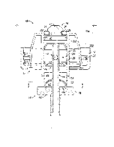
comprising passing
fluid longitudinally outwardly and preferably downwardly through an elongate
discharge
passageway as a fluid stream to thereby dispense the stream at a preferably
downwardly directed
discharge outlet of the passageway preferably open to the atmosphere, and
injecting an allotment
of air into the passageway proximate the discharge outlet with the injected
allotment of air
having a volume sufficient to substantially sever an inner stream portion of
the fluid stream
inward of the injected allotment of air from an outer stream portion of the
fluid stream outward
of the injected allotment of air. Preferably, the step of injecting the
allotment of air into the
passageway includes displacing with the injected air the outer stream portion
outwardly in the
passageway relative the inner stream portion.
[0007] The method may be carried out in an apparatus which will discharge the
fluid and
will provide pressurized air at a suitable location in a stream of discharge
fluid preferably within
a discharge passageway within a stream of fluid being discharged is
contrained. Almost any
manner of pump may be used to discharge the fluid and the pressurized air may
come from
various sources such as pumps and reservoirs of pressurized air.
[0008] The method is particularly advantageous for use with fluids having a
sufficiently high
viscosity to assist in resisting flow of air upwardly within the fluid in the
discharge passageway
through the inner stream portion. The passageway preferably has a cross-
sectional area selected
having regard to the viscosity of the fluid so as to assist in resisting flow
of air upwardly within
the fluid in the passageway through the inner stream portion.
[0009] The method in accordance with the present invention is preferably
carried out with
viscous and viscoelastic flowable materials, however, is not limited to the
extent that the fluid
may not be viscous or viscoelastic, then the injection of air into a discharge
passageway can
serve to extrude with the allotment of air fluid within the passageway
downstream from the point
of injection of the air as can have the advantage of clearing the discharge
outlet of fluid. The
present invention is particularly advantageous for use of fluids which are
viscous or viscoelastic.
The extent to which the viscous or viscoelastic fluid will have an impact on
whether an air
bubble may be formed in the discharge passageway by the injection of air. The
creation of an air
2
CA 02722646 2010-11-26
bubble and its subsequent sudden violent discharge can be of substantial
assistance in providing
for a complete severance of viscous and viscoelastic fluids.
[00101 Preferably, the method is carried out wherein after injecting the
allotment of air into
the passageway so as to substantially sever the inner stream portion from the
outer stream
portion, then drawing the inner stream portion of the fluid stream
longitudinally inwardly and
upwardly within the discharge passageway to assist in severing the inner
stream portion from the
outer stream portion.
100111 The method may be carried out using a pump which is operated to pass
the fluid
longitudinally outwardly through an elongate discharge passageway with the
pump preferably
comprising a piston pump having a piston-forming element reciprocally
removable relative to a
piston chamber-forming body to pass fluid longitudinally through the
passageway. Preferably,
the injection of the allotment of air is via an air port opening into the
passageway and, optionally,
after injecting the allotment of air into the passageway, the method is
carried out to draw air back
via the air port from the passageway. Preferably, after injecting the
allotment of air into the
passageway so as to substantially sever the inner stream portion from the
outer stream portion,
the pump is operated to drawback the inner stream portion of the fluid stream
longitudinally
inwardly within the passageway.
100121 The invention provides an advantageous piston pump assembly in which
the piston
has a two-piece construction which selectively collapses during a stroke of
operation as to
discharge fluid during an initial segment of movement in one stroke and to
then discharge air in a
later segment of a stroke, preferably a retraction stroke. The piston pump in
accordance with the
present invention can be manually operated or operated by an automatic motor
powered actuator.
Use of a motor powered actuator is advantageous so as to ensure that the pump
is cycled through
a full cycle of operation.
100131 The method in accordance with the present invention is preferably
operated such that
the injection of the allotment of air forms an air bubble in the passageway,
which air bubble
preferably extends across a substantial portion of the cross-section of the
passageway and, more
preferably, with the air bubble extending from within the passageway to at
least partially
outwardly of the discharge opening of the passageway. The method may be also
carried out such
3
CA 02722646 2010-11-26
that an air bubble is formed by the allotment of air to extend at least
partially outwardly of the
discharge opening and while the air bubble extends outwardly of the discharge
opening
collapsing the bubble preferably suddenly as by continued injection of air to
enlarge the bubble
outwardly of the discharge opening so that it collapses. Drawing air back via
the air port from
the passageway and/or drawing the inner stream portion of the fluid stream
longitudinally
inwardly and upwardly within the passageway are other methodologies used
towards assisting in
stressing, breaking or collapsing the bubble and severing any remaining fluid
connecting the
inner stream portion from the outer stream portion after collapse of the
bubble. Relatively
sudden collapse of the air bubble can be violent and, for example, generate
sound pressures
which are believed to assist in severing the walls of the bubble which
otherwise would join the
inner stream portion and the outer stream portion.
[0014] The method in accordance with the present invention may be carried out
in a wide
manner of different mechanisms preferred of which comprise piston pumps. The
invention is not
limited to the use of piston pumps.
[0015] In one aspect, the present invention provides a method of dispensing a
fluid
comprising:
passing fluid longitudinally outwardly and downwardly through an elongate
discharge
passageway as a fluid stream to thereby dispense downwardly the stream at a
downwardly directed
discharge outlet of the passageway open to the atmosphere, and
injecting an allotment of air into the passageway proximate the discharge
outlet of a
volume sufficient to substantially sever an inner stream portion of the fluid
stream inward of the
injected allotment of air from an outer stream portion of the fluid stream
outward of the injected
allotment of air.
[0016] In another aspect, the present invention provides a piston pump
comprising a piston
chamber-forming body and a piston element reciprocally slidable relative the
body about an axis,
the piston element including a sleeve portion and a tube portion ,
the sleeve portion disposed coaxially about the axis annularly about the tube
portion,
the tube portion coaxially slidable along the axis relative the sleeve
portion,
the tube portion having an elongate discharge passageway and a discharge
outlet,
4
CA 02722646 2010-11-26
the sleeve portion coaxially slidable relative the body along the axis between
a
retracted position and extended position,
the tube portion captured for axial between the sleeve portion and the body
such that
relative outward sliding of the tube portion on the sleeve is limited to an
outer position relative
the sleeve portion by engagement of an outwardly directed stop surface on the
tube portion with
an inwardly directed stop surface on the sleeve portion and relative inward
sliding of the tube
portion relative the body is limited to an inner position relative the body by
engagement of an
inwardly directed stop surface of the tube portion with an outwardly directed
stop surface on the
body,
in sliding of the sleeve portion inwardly relative the body from the extended
position
toward the retracted position, the sleeve portion moves the tube portion
inwardly from the outer
position to the inner position with, when the tube portion is in the inner
position relative the
sleeve portion, the sleeve portion is in a partially retracted position
intermediate the extended
position and the retracted position,
in sliding of the sleeve portion inwardly from the partially retracted
position to the
retracted position the sleeve portion moves inwardly relative both the body
and the tube portion,
a fluid compartment selected from the group consisting of a fluid compartment
defined between the body and the tube portion and a fluid compartment defined
between the
body, the tube portion and the sleeve,
the fluid compartment in communication with a fluid in a reservoir by a one-
way
valve permitting fluid flow outwardly from the reservoir to the fluid
compartment but preventing
fluid flow inwardly,
an air compartment selected from the group of an air compartment defined
between
the tube portion and the sleeve portion and an air compartment defined between
the sleeve
portion and the body,
on sliding of the sleeve portion inwardly from the extended position to the
partially
retracted position with the sleeve portion moving the tube portion inwardly
from the outer
position to the inner position, a volume of the fluid compartment is reduced
discharging fluid
CA 02722646 2010-11-26
from the fluid compartment as a fluid stream through the passageway of the
tube portion and out
the discharge opening,
on sliding of the sleeve portion inwardly from the partially retracted
position to the
retracted position, a volume of the air compartment is reduced discharging air
from the air
compartment into the fluid stream in the elongate discharge passageway,
on sliding of the sleeve portion outwardly from the fully retracted position
to the
partially retracted position, the volume of the air compartment increases
drawing air into the air
compartment, and
on sliding of the sleeve portion outwardly from the partially retracted
position toward
the extended position, the tube portion moves outwardly toward the outer
position and the
volume of the fluid chamber increases drawing fluid from the fluid reservoir
past the one way
valve into the fluid chamber. Preferably, the piston pump as includes a spring
member biasing
the sleeve portion biased outwardly relative the tube portion. Preferably in
the piston pump, the
sleeve portion carries an engagement flange for engagement by an actuator
adapted to slide the
sleeve portion relative the body.
[0017] In yet another aspect, the present invention provides a piston pump
comprising a
piston chamber forming body and a piston element reciprocally slidable
relative the body about
an axis,
the piston element including a sleeve portion and a tube portion,
the sleeve portion coaxially slidable relative the body along the axis
between a fully retracted position and extended position,
the tube portion coaxially slidable relative the body along the axis and
coaxially
slidable relative the sleeve portion between an outer position and an inner
position to discharge
fluid through a passageway and out a discharge outlet,
the body engaging the tube portion to prevent inward movement of the tube
portion
relative the body past the inner position,
the sleeve portion engaging the tube portion to prevent outward movement of
the tube
portion relative the body past the outer position,
6
CA 02722646 2010-11-26
wherein on sliding of the sleeve portion inwardly from the extended position
toward
the fully retracted position, the sleeve portion moves the tube portion
inwardly from the outer
position to the inner position and movement of the tube portion inwardly from
the outer position
to the inner position discharges fluid as a fluid stream through the
passageway and out a
discharge opening,
wherein on sliding of the sleeve portion inwardly from the extended position
toward
the fully retracted position on the tube portion reaching the inner position
the sleeve portion is in
a partially retracted position intermediate the extended position and the
retracted position,
wherein on sliding of the sleeve portion inwardly from the partially retracted
position
to the fully retracted position, the sleeve portion moves coaxially inwardly
relative to both the
body and to the tube portion and discharges air into the fluid stream in the
elongate discharge
passageway.
[00181 In yet another aspect, the present invention provides a fluid discharge
nozzle
providing a passageway for passage of a stream of fluid to an outlet and
providing for air to be
discharged into the fluid stream to assist in severing the fluid stream.
Preferably, the passageway
is provided within a hollow tubular stem and a tube is provided concentrically
about the stem to
selectively deliver air from coaxially between the stem and the tube into the
fluid stream while
the fluid is constrained within the stem and/or the tube.
Brief Description of the Drawings
100191 Further aspects and advantages of the present invention will become
apparent from
the following description taken together with the accompanying drawings in
which:
[00201 Figure 1 is a partially cut-away side view of a first embodiment of a
liquid dispenser
with a reservoir and a pump assembly in accordance with the present invention;
100211 Figure 2 is a schematic cross-sectioned side view of a pump assembly in
accordance
with a first embodiment of the present invention is a fully extended position;
100221 Figure 3 is a cross-sectional side view of the pump assembly of Figure
2 in a partially
retracted position in a retraction stroke;
7
CA 02722646 2010-11-26
[0023] Figure 4 is a cross-sectional side view of the pump of Figure 2 in a
fully retracted
position;
[0024] Figure 5 is a cross sectional side view of the pump assembly of Figure
2 in a partially
retracted position in a withdrawal stroke;
[0025] Figure 6 is a cross-sectional exploded side view of the piston of the
pump of Figure 2;
[0026] Figure 7 is a cross-sectional view along section line 7-7' in Figure 2;
[0027] Figure 8 is an enlarged cross-sectional side view of the pump assembly
of Figure 2
within the broken line circle indicated in Figure 2 but additionally showing
fluid being
dispensed;
[0028] Figure 9 is an enlarged cross-sectional side view the same as in Figure
8, however,
showing a condition with the pump assembly in a retraction stroke in the
partially retracted
position as shown in Figure 3;
[0029] Figure 10 is an enlarged cross-sectional side view the same as in
Figure 8 showing a
condition with the pump assembly in a retraction stroke in a first retracted
position between the
partially retracted position of Figure 3 and the fully retracted position of
Figure 4;
[0030] Figure 11 is an enlarged cross-sectional side view the same as in
Figure 8 showing a
condition with the pump assembly in a retraction stroke in a second retracted
position between
the partially retracted position of Figure 3 and the fully retracted position
of Figure 4;
[0031] Figure 12 is an enlarged cross-sectional side view the same as in
Figure 8 showing a
condition with the pump assembly in a retraction stroke in a third retracted
position between the
partially retracted position of Figure 3 and the fully retracted position of
Figure 4;
[0032] Figure 13 is an enlarged cross-sectional side view the same as in
Figure 8 showing a
condition with the pump assembly in a retraction stroke in a fourth retracted
position between the
partially retracted position of Figure 3 and the fully retracted position of
Figure 4;
[0033] Figure 14 is an enlarged cross-sectional side view the same as in
Figure 8 showing a
condition with the pump assembly in a retraction stroke with the fully
retracted position of
Figure 4;
[0034] Figure 15 is an enlarged side view the same as Figure 8 showing a
condition with the
pump assembly in a withdrawal stroke in a position between the position of
Figure 4 and Figure 5;
8
CA 02722646 2010-11-26
[0035] Figure 16 is an exploded view similar to Figure 6 but showing an
alternate
construction for the piston;
[0036] Figure 17 is a schematic cross-section side view of a pump assembly in
accordance
with a second embodiment of the present invention in a fully extended
position;
[0037] Figure 18 is a cross-sectional side view of the pump assembly of Figure
17 in a
partially retracted position;
[0038] Figure 19 is a cross-sectional side view of the pump of Figure 17 in a
fully retracted
position;
[0039] Figure 20 is a schematic cross-sectional side view of a pump assembly
in accordance
with a third embodiment of the present invention in a partially retracted
position similar to
Figure 3;
[0040] Figure 21 is a cross-sectional side view of the pump assembly of Figure
20 in a fully
retracted position;
[0041] Figure 22 is a schematic cross-sectional side view of a pump assembly
in accordance
with a fourth embodiment of the present invention in a fully extended position
at the
commencement of a retraction stroke;
[0042] Figure 23 is a cross-sectional side view of the pump of Figure 22 in a
partially
retracted position in a retraction stroke;
[0043] Figure 24 is a cross-sectional view of the pump assembly of Figure 22
in a fully
retracted position;
[0044] Figure 25 is a cross-sectional side view of the pump of Figure 22 in a
partially
retracted position in a withdrawal stroke;
[0045] Figure 26 is an enlarged cross-sectional side view of the pump assembly
of Figure 22
within the broken line circle indicated in Figure 24 additionally showing
fluid being dispensed in
a condition with the pump assembly in a retraction stroke in the fully
retracted position of Figure
24;
[0046] Figure 27 is an enlarged cross-sectional side view the same as in
Figure 26, however,
showing a condition with the pump assembly in a withdrawal stroke in the
partially retracted
position as in Figure 25;
9
CA 02722646 2010-11-26
[0047] Figure 28 is a schematic cross-sectional side view of a pump assembly
in accordance
with a fifth embodiment of the present invention in a fully retracted position
at the
commencement of the retraction stroke;
[0048] Figure 29 is a cross-sectional side view of the pump assembly of Figure
28 in a
partially retracted position in a retraction stroke;
[0049] Figure 30 is a cross-sectional side view of the pump assembly of Figure
29 in a fully
retracted position;
[0050] Figure 31 is a cross-sectional side view of the pump assembly of Figure
29 in a
partially retracted position in a withdrawal stroke; and
[0051] Figure 32 is a schematic cross-sectional side view of a pump assembly
in accordance
with a sixth embodiment of the present invention in a fully retracted position
at the
commencement of the retraction stroke.
Detailed Description of the Drawings
[0052] Reference is now made to Figure 1 which shows a liquid soap dispenser
generally
indicated 200 utilizing a pump assembly 10 coupled to the neck 202 of a
sealed, collapsible
container or reservoir 204 containing liquid hand soap 11 to be dispensed.
Dispenser 200 has a
housing generally indicated 206 to receive and support the pump assembly 10
and the reservoir
204. Housing 206 is shown with a back plate 208 for mounting the housing, for
example, to a
building wall 210. A bottom support plate 212 extends forwardly from the back
plate to support
and receive the reservoir 204 and pump assembly 10. The pump assembly 10 is
only
schematically shown in Figure 1, as including a slidable piston 14. As shown,
bottom support
plate 212 has a circular opening 214 therethrough. The reservoir 204 sits
supported on a
shoulder 216 of the support plate 212 with the neck 202 of the reservoir 204
extending through
the opening 214 and secured in the opening as by a friction fit, clamping and
the like. A cover
member 218 is hinged to an upper forward extension 220 of the back plate 208
so as to permit
replacement of reservoir 202 and its pump assembly 10.
[0053] Support plate 212 carries at a forward portion thereof an actuating
lever 222
journalled for pivoting about a horizontal axis at 224. An upper end of the
lever 222 carries a
CA 02722646 2010-11-26
hook 226 to engage an engagement disc 78 carried on the piston 14 of the
piston pump 10 and
couple the lever 222 to piston 14 such that movement of the lower handle end
228 of lever 222
from the dashed line position to the solid line position, in the direction
indicated by arrow 230
slides piston 14 inwardly in a retraction or discharge pumping stroke as
indicated by arrow 232.
On release of the lower handle end 228, a spring 234 biases the upper portion
of lever 222
downwardly so that the lever draws piston 14 outwardly to a fully withdrawn
position as seen in
dashed lines in Figure 1. Lever 222 and its inner hook 226 are adapted to
permit manual
coupling and uncoupling of the hook 226 as is necessary to remove and replace
reservoir 204 and
pump assembly 10. Other mechanisms for moving the piston 14 can be provided
including
mechanised and motorized mechanisms.
[0054] In use of the dispenser 200, once exhausted, the empty, collapsed
reservoir 204
together with the attached pump assembly 10 are preferably removed and a new
reservoir 204
and attached pump assembly 10 may be inserted into the housing.
[0055] Reference is made first to Figures 2 to 15 which schematically
illustrate a pump
assembly 10 in accordance with a first embodiment of the present invention
generally adapted to
be used as the pump assembly 10 shown in Figure 1.
[0056] The pump assembly 10 comprises three principle elements, a piston
chamber-forming
body 12, a piston-forming element or a piston 14, and a one-way inlet valve
16. The body 12
carries an outer annular flange 18 with internal threads 20 which are adapted
to engage threads of
the neck 202 of a bottle reservoir 204 shown in dashed lines only in Figure 2.
[0057] The body 12 includes an interior center tube 22 which defines a
cylindrical chamber
24 therein. The chamber 24 has a chamber wall 26 being the inside surface of
the center tube 22
and extends axially from an inner end 28 outwardly to an outer end at the
axially outwardly
directed end surface 30 of the center tube 22. The chamber wall 26 is
cylindrical.
[0058] The body 12, center tube 22 and chamber 24 are coaxially about a
central axis 32.
[0059] An end flange 34 extends across the inner end 28 of the chamber 24 and
has a central
opening 36 and a plurality of inlet orifices 38 therethrough. The one-way
valve 16 is disposed
across the inlet openings 38. The inlet orifices 38 provide communication
through the flange 34
11
CA 02722646 2010-11-26
with fluid in the reservoir 204. The one-way valve 16 permits fluid flow from
the reservoir 204
into the chamber 24 but prevents fluid flow from the chamber 24 to the
reservoir 204.
[0060] The one-way valve 16 comprises a shouldered button 40 which is secured
in snap-fit
relation inside the central opening 36 in the flange 34 with a circular
resilient flexing disc 42
extending radially from the button 40. The flexing disc 42 is sized to
circumferentially abut the
chamber wall 26 of the chamber 24 substantially preventing fluid flow
therepast inwardly from
the chamber 24 to the reservoir 204. The flexing disc 42 is deflectable away
from the wall 26 to
permit flow therepast outwardly from the reservoir 204 into the chamber 24.
[0061] The piston 14 is axially slidably received in the chamber 24 for
reciprocal coaxial
sliding inwardly and outwardly therein. The piston 14 is generally circular in
cross-section as
seen in Figure 7. As best seen in Figure 6, the piston 14 is formed from two
elements, namely, a
stem portion 44 and a sleeve portion 46. The stem portion 44 has a hollow stem
48 extending
along the central longitudinal axis 32 through the piston 14.
[0062] A generally circular resilient flexing inner disc 50 is located at an
inner end 52 of the
stem portion 44 and extends radially therefrom. The inner disc 50 is adapted
to be located in the
chamber 24 with the inner disc 50 extending radially outwardly on the stem 48
to
circumferentially engage the chamber wall 26. The inner disc 50 is sized to
circumferentially
abut the chamber wall 26 of the chamber 24 to substantially prevent fluid flow
therebetween
inwardly. The inner disc 50 is preferably biased radially outwardly and is
adapted to be
deflected radially inwardly so as to permit fluid flow past the inner disc 50
outwardly.
[0063] A generally circular outer disc 54 is located on the stem 48 spaced
axially outwardly
from the flexing disc 50. The outer disc 54 is adapted to be located in the
chamber 24 with the
outer disc 54 extending radially outwardly on the stem 48 to circumferentially
engage the
chamber wall 26 of the chamber 24. The outer disc 54 is sized to
circumferentially abut the
chamber wall 26 of the chamber 24 to substantially prevent fluid flow
therebetween outwardly.
The outer disc 54 is preferably biased radially outwardly and may optionally
be adapted to be
deflected radially inwardly so as to permit fluid flow past the outer disc 54
inwardly. Preferably,
the outer disc 54 engages the chamber wall 26 of the chamber 24 to prevent
flow therepast both
inwardly and outwardly.
12
CA 02722646 2010-11-26
[0064] The piston stem 48 has a hollow central outlet passageway 56 extending
along the
axis of the piston stem from a closed inner end 58 to a discharge outlet 60 at
an outer end 62 of
the stem portion 44. An outlet opening 64 extends radially through the stem 48
into
communication with the central passageway 56. The outlet opening 64 is located
on the side of
the stem 48 between the inner disc 50 and the outer disc 54. The outlet
opening 64 and central
passageway 56 permit fluid communication through the piston 14 past the outer
disc 54 between
the outlet opening 64 and the outlet 60.
[0065] The stem portion 44 carries on the stem 48 outwardly of the outer disc
54 a resilient
spring bellows disc 66 comprising a thin walled disc joined at a radially
inner end 68 to the stem
48 and extending radially outwardly and axially outwardly to an outer end 70
such that the
bellows disc 66 has a bell or cup shape opening outwardly. Outwardly of the
inner end 68 of the
bellows disc 66, the stem 48 has an outer wall 72 which is cylindrical where
it extends from the
bellows disc 66 to the outer end 62.
[0066] As best seen in Figure 6, the sleeve portion 46 comprises a tube 74
with a central bore
76 therethrough coaxial about the axis 32. The bore 76 through the tube 74 has
a radially
inwardly directed interior surface 88 sized to permit the stem 48 of the stem
portion 44
outwardly of the bellows disc 66 to be received therein and to be relatively
slidable coaxially.
As best seen in Figure 8, the relative diameters of the interior surface 88 of
the tube 74 and the
outer wall 72 of the stem 48 provide an axially extending substantially
annular passageway 90
therebetween. The tube 74 has the engagement flange 78 extend radially
outwardly therefrom.
The engagement flange 78 is adapted to be engaged by an actuating device, such
as the lever 222
in Figure 1, in order to move the sleeve portion 46 and hence the piston 14 in
and out of the body
12. A centering ring 82 extends axially inwardly from the engagement flange 78
coaxially about
the axis 32 and presents a radially outwardly directed cylindrical wall
surface 82 for engagement
with the chamber wall 26 of the chamber 24 so as to assist in maintaining the
sleeve portion 46
coaxially disposed within the chamber 26 of the body 12. An annular axially
inwardly directed
shoulder surface 84 of the sleeve portion 46 is provided radially inwardly of
the centering ring 80
and carries a circular axially outwardly extending slot 86 open axially
inwardly.
13
CA 02722646 2010-11-26
[0067] From the exploded condition of the stem portion 44 and the sleeve
portion 46 as
shown in Figure 6, these elements are assembled into the piston 14 by sliding
the outer end 62 of
the stem 48 of the stem portion 44 axially into the bore 76 of the sleeve
portion 46 so as to
receive the outer end 70 of the bellows disc 66 within the slot 86 carried on
the shoulder surface
84 of the sleeve portion 46. The outer end 70 of the bellows disc 66 is
secured in the slot 86
against removal as, for example, by the use of an adhesive. In the assembled
piston as shown,
for example, in Figure 2, an annular inner air compartment 92 is defined
within inside of the
bellows disc 66 and bordered by the axially inwardly directed shoulder surface
84 of the sleeve
portion 46 and the outer wall of the stem 48. The air compartment 92 is open
outwardly via the
annular passageway 90 between the tube 74 and the stem 48. For ease of
illustration, the annular
passageway 90 is generally not shown other than in the enlarged view of
Figures 8 to 15.
[0068] The pump assembly 10 is operative to dispense fluid 11 from the
reservoir 204 in a
cycle of operation in which the piston 14 is reciprocally slidable coaxially
within the chamber 24
and with the cycle of operation involving a retraction stroke and a withdrawal
stroke. Such a
cycle of operation is illustrated having regard to Figures 2 to 5 with Figure
2 representing a fully
withdrawn position and Figure 4 representing a fully retracted position and
each of Figures 3 and
representing partially retracted positions. A retraction stroke is indicated
by movement of the
piston 14 relative the body 12 from the position of Figure 2 axially inwardly
to the partially
retracted position of Figure 3 and then axially inwardly to the fully
retracted position of Figure 4.
A withdrawal stroke is indicated by movement of the piston 14 relative the
body 12 from the
fully retracted position of Figure 4 axially outwardly to the partially
retracted position of Figure
5 and then axially inwardly to the fully extended position shown of Figure 2.
On movement
from the fully extended position of Figure 2 to the partially retracted
position of Figure 3, axially
inward movement of the sleeve portion 46 is transferred via the bellows disc
66 to the stem
portion 44 to move the stem portion 44 axially inwardly until, as shown in
Figure 3, the inner
end 52 of the stem 48 engages the one-way valve 16 and further inward movement
of the stem
portion 44 is prevented. In the retraction stroke in moving from the fully
extended position of
Figure 2 to the partially retracted position of Figure 3, the bellows disc 66
transfers forces from
the sleeve portion 46 to the stem portion 44 such that the sleeve portion 46
and stem portion 44
14
CA 02722646 2010-11-26
move in unison together inwardly substantially without relative movement thus
moving the stem
portion 44 inwardly without a change in the volume of the air compartment 92.
In the position
of Figure 3, an axially inwardly directed stop surface 96 on the engagement
flange 78 radially
outwardly of the centering ring 80 is axially spaced from the outer end 30 of
the center tube 22
of the body 12. On axial inward movement of the sleeve portion 46 from the
position of Figure 3
to the position of Figure 4, the sleeve portion 46 moves axially relative to
both the stem portion
44 and the body 12 until the stop surface 96 on the engagement flange 78
engages the outer end
30 of the center tube 22 of the body 12. In moving inwardly from the position
of Figure 3 to the
position of Figure 4, the bellows disc 66 is deformed from a bell shaped
uncollapsed
configuration shown in Figure 3 to a collapsed configuration shown in Figure 4
and such
collapse of the bellows disc 66 reduces the volume of the air compartment 92
thus discharging
air outwardly from the air compartment 92 through the annular passageway 90 to
exit the annular
passageway at an annular outlet 98 between the tube 74 and the stem 48.
[0069] In the withdrawal stroke on movement from the fully retracted position
of Figure 4 to
the partially retracted position of Figure 5, the sleeve portion 46 moves
axially outwardly relative
to both the stem portion 44 and the body 12. In such outward movement from the
position of
Figure 4 to the position of Figure 5, the bellow disc 66 moves from the
collapsed condition as
shown in Figure 4 to the uncollapsed condition shown in Figure 5 and, in so
doing, increases the
volume of the air compartment 92 resulting with a drawing in of air through
the annular outlet 98
via the annular passageway 90 into the air compartment 92. In the withdrawal
stroke in moving
from the partially retracted position of Figure 5 to the fully extended
position of Figure 2, the
bellows disc 66 transfers forces from the sleeve portion 46 to the stem
portion 44 such that the
sleeve portion 46 and stem portion 44 move in unison together outwardly
substantially without
relative movement thus moving the stem portion 44 outwardly without a change
in the volume of
the air compartment 92.
[0070] Movement of the stem portion 44 relative to the body 12 in the
retraction stroke in
moving from the position of Figure 2 to the position of Figure 3 provides for
discharge of fluid
from the chamber 24 outwardly through the discharge outlet 60 of the outlet
passageway 56. In
this regard from the position of Figure 2 on movement of the stem portion 44
inwardly, fluid in
CA 02722646 2010-11-26
the chamber 26 between the one-way valve 16 and the inner disc 50 is
pressurized, deflecting the
inner disc 50 so as to permit fluid to flow outwardly past the inner disc 50
and into an annular
space within the chamber 24 between the inner disc 50 and the outer disc 54
and hence via the
outlet opening 64 into the outlet passageway 56 and axially through the outlet
passageway 56 to
exit the discharge outlet 60. In the withdrawal stroke, on movement of the
stem portion 44 from
the position of Figure 5 to the position of Figure 2, a vacuum is created
within the chamber 24
between the inner disc 50 and the one-way valve 16 which deflects the disc 42
of the one-way
valve 16 to permit fluid flow outwardly therepast such that fluid flows from
the reservoir 204
through the inlet orifices 38 into the chamber 24.
[0071] In a cycle of operation, in a retraction stroke on moving from the
fully extended
position of Figure 2 to the position of Figure 3, fluid is discharged from the
discharge outlet 60
and the volume of the air compartment 92 is maintained substantially constant.
In movement
from the position of Figure 3 to the fully retracted position of Figure 4, air
is discharged from the
air compartment 92 via the annular outlet 98 and fluid is not substantially
discharged out or
drawn back in through the outlet opening 60. In a withdrawal stroke in moving
from the position
of Figure 4 to the position of Figure 5, air is drawn into the air compartment
92 via the annular
outlet 98 and fluid is not substantially drawn in back or discharged out
through the outlet
opening 60. In moving from the position of Figure 5 to the fully extended
position of Figure 2,
fluid is drawn into the chamber 24 from the reservoir 204 without fluid being
dispensed out the
discharge outlet 60.
[0072] Reference is made to Figures 8 to 15 which each show an exploded view
of the outlet
end of the piston 14 as shown within the circle of dashed lines in Figure 2,
however, additionally
schematically showing a stream 102 of the fluid 11 as it is discharged in
conjunction with air
discharged from the air compartment 92. Figures 8 to 15 represent successive
steps in a cycle of
operation of the piston pump.
[0073] Figure 8 illustrates the relative condition of the stem 48 and the tube
74 in a fully
extended position as shown in Figure 2. In this position, the stem 48 may be
considered to be
fully retracted compared to the tube 74. Figure 14 illustrates a condition as
shown in Figure 4 in
which the piston 14 is fully retracted relative to the body 12 and
correspondingly the stem 48 is
16
CA 02722646 2010-11-26
fully extended relative to the tube 74. Thus, Figures 8 and 14 represent the
extreme positions of
relative movement of the stem 48 relative to the tube 74. This relative
position of extension of
the tube 74 relative to the stem 48 is for discussion to be considered defined
as a 100% position
in Figure 14 and the relative position of extension of the tube 74 relative to
the stem 48 is to be
defined as a 0% position in Figure 8. The relative extension positions of the
tube 74 relative to
the stem 48 are a 0% position in Figure 8, a 0% position in Figure 9, a 20%
position in Figure 10,
a 35% position in Figure 11, a 65% position in Figure 12, an 80% position in
Figure 13, a 100%
position in Figure 14 and an 80% position in Figure 15. In moving from the
position of Figure 2
to the position of Figure 4, Figures 8 to 14 in sequence represent the
relative percentage
movement of the tube 74 relative to the stem 48. Figure 15 represents a
position assumed in
movement from the fully retracted position of Figure 4 towards the partially
retracted position of
Figure 5.
[0074] The representations of Figures 8 to 15 are intended to schematically
illustrate one
possible explanation for operation of the first embodiment of the pump in
accordance with the
present invention as observed by the applicant by simple experiment when
dispensing a viscous
liquid hand cream.
[0075] Referring to Figure 8, Figure 8 illustrates an initial condition of the
pump 10 as
shown in Figure 2 in which condition the pump may rest between cycles of
operation. As seen
in Figure 8, the stream 102 of fluid fills the stem 48 to its outer end 62 and
provides a meniscus
104 facing downwards. On movement from the position of Figure 2 to the
position of Figure 3,
the stream 102 of fluid is discharged from and extends out of the outer end 62
of the stem 48
downwardly through the outer end 94 of the tube 74. The stream 102 may be
considered to
comprise an inner portion 106 within the stem 48 and an outer portion 108
downward from the
stem 48.
[0076] Figure 10 illustrates a condition in the retraction stroke in which the
sleeve portion 46
has been moved upwardly relative to the stem portion 44, 20% of the total
axial amount that the
sleeve portion 46 can move relative to the stem portion 44. With movement of
the sleeve portion
46 upwardly relative the stem portion 44, the bellows disc 66 is partially
collapsed such that the
volume of the air compartment 92 is reduced and a volume of air has been
ejected out the
17
CA 02722646 2010-11-26
annular outlet 98 and inside the tube 74 at the outer end 62 of the stem 48.
This ejected air is
schematically illustrated as forming a pocket or bubble 110 of air within the
fluid stream 102
within the tube 74. As well, with the relative upward and axially inward
movement of the tube
74, there is a tendency for engagement between the fluid stream 102 and the
interior surface 88
of the tube 74 to attempt to draw the fluid stream 102 upwardly into the outer
end 62 of the stem
48. This upward drawing of the liquid stream 102 may be of assistance in
engaging the fluid
stream with the inner surface 88 of the tube 74 as can be of assistance
towards having the air
bubble 110 in being formed to extending radially into the fluid stream 102 as
contrasted with
merely passing axially outwardly through the fluid stream to the atmosphere.
[0077] Figure 11 illustrates a condition after further inward movement of the
sleeve portion
46 relative to the stem portion 44 from the position of Figure 10 with
additional air being ejected
from the air chamber 92 out the annular outlet 98 thus increasing the volume
of air in the air
bubble 110 and with the tube 74 continuing to be moved axially inwardly
relative to the stem 48.
[0078] Figure 12 illustrates a condition which arises from the position of
Figure 11 in which
the sleeve portion 46 further moves axially upwardly relative to the stem
portion 44 with the
volume of the air compartment 92 continuing to be reduced and additional air
being injected to
increase the size of the air bubble 110 and with the air bubble 110 becoming
sufficiently large
that it has formed a side wall 113 bulging radially outwardly. In Figure 12,
the outer end 62 of
the stem 48 continues to be axially inwardly of the tube 74.
[0079] Figure 13 illustrates a condition which arises with further relative
axial upward
movement of the sleeve portion 46 relative to the stem portion 44 such that
the volume of the air
compartment 92 is reduced ejecting further air into air bubble 110 and with
the outer end 62 of
the stem 48 shown to be axially aligned with the outlet end 94 of the bore 78.
The air bubble 110
is shown as having its wall 113 formed by the fluid about the air bubble at
each annular side
further expanded radially outwardly beyond the stem 48 and the tube 74.
[0080] Figure 14 illustrates a condition which arises with further relative
axial upward
movement of the sleeve portion 46 relative to the stem portion 44 such that
the volume of air in
the air compartment is reduced ejecting further air into the air bubble 110 so
that the air bubble
110 has broken at its radially side wall 113. From the position of Figure 13
in moving to the
18
CA 02722646 2010-11-26
position of Figure 14 the sleeve portion 46 has been drawn axially inwardly
relative to the stem
portion 44 with the outer end 62 of the stem 48 has extended axially outwardly
beyond the outer
end 94 of the tube 74 presenting the annular outlet 98 for the air axially
inwardly of the outer end
62 of the stem 48. The outlet end 94 of the tube 74 has been moved axially
upwardly beyond the
outer end 62 of the stem 48. Such movement and configuration is believed to be
advantageous
with the ejection of air for the wall 113 of the bubble 110 at the radial
sides of the bubble 110 to
become sufficiently thinned and tensioned so as to rupture and collapse as
schematically
illustrated in Figure 14.
[0081] Figure 15 illustrates a condition subsequent to Figure 14 in which from
the position of
Figure 14 represented by the fully retracted position of Figure 4, in a
withdrawal stroke, the
sleeve portion 46 moves axially outwardly relative to the stem portion 48,
such that the outer end
94 of the tube 74 moves axially inwardly relative to the outer end 62 of the
stem 48 and, at the
same time, the volume of the air compartment 92 increases drawing air inwardly
into the air
compartment 92 via the annular outlet 98. An outer portion 108 of the stream
102 is shown
falling downwardly under gravity as indicated by the arrow 114, with the outer
portion 108 fully
separated from the inner portion 106 of the stream 102. A meniscus 104 is
again shown as being
formed at the outer end of the inner portion 106 of the stream 102 across the
stem 48.
[0082] In the sequence of operation from the position of Figure 8 through to
the position of
Figure 15, it is to be appreciated that, as seen in Figure 9, the stream 102
of fluid is formed
which extends downwardly from the stem 48 and tube 74 as a continuous stream
as will be the
case particularly with viscous products such as honey. In Figure 10, with
collapse of the air
compartment 92, an allotment of air is ejected into the fluid stream 102
towards initiating
separation of an inner portion 106 of the stream 102 from the outer portion
108 of the stream.
With increased ejection of air between the inner portion 106 and outer portion
108, the inner
portion 106, the air bubble 110 becomes enlarged and tends to extrude the
outer portion 108 of
the fluid stream 102 outwardly with the outer portion 108 coming to be severed
from the inner
portion 106 sufficient that the severed outer portion 108 may be discharged to
drop downwardly.
Rapid sudden violent breaking of the air bubble 110 is believed to assist in
breaking connection
even in viscoelastic fluids between the inner stream portion 106 and outer
stream portion 108.
19
CA 02722646 2010-11-26
[0083] The particular nature of the formation of the air pocket or bubble 110
is not limited to
that shown in the exemplary schematic drawings. Rather than a single air
pocket or bubble 110,
a plurality of pockets or bubbles may be formed which preferably disseminate
radially inwardly
from the annular outlet 98 as to coalesce and form at least partially across
the horizontal cross-
section of the fluid stream at a location where the stream inner portion 106
at least commences to
be separated from the outer portion 108 and providing an air pocket or bubble
or air pockets or
bubbles into which further air to be ejected can further assist in severing
the stream inner portion
106 from the stream outer portion 108 and displace the outer portion 108
outwardly. The air
bubble or bubbles 110 preferably have a wall 113 thereabout formed from the
fluid 11 and
having weakened portions radially outwardly over at least some circumferential
extent of the
fluid stream 102 such that with rupturing of the wall 113 at weakened radial
portions, there is an
initiation over at least some cross-sectional area of at least partial
severance of the stream inner
portion 106 from the stream outer portion 108, which at least partial
severance can then be of
assistance in further spreading across the entire cross-section of the stream
102 leading towards
severance. This severance is assisted in part by gravity acting on the stream
outer portion 108
axially outward of the stem 48 and tube 74, the relative movements of the stem
48 and the tube
74, the ejection of air, cessation of injection of air and withdrawal of air.
[0084] The air bubble 110 in one sense is functionally similar to an air wedge
extending
radially into the stream 102 and being a location for initiation of
separation. The air bubble 110
in another sense in expanding extrudes the stream outer portion 108 away from
the stream inner
portion 106. The air bubble 110 in another sense provides a joining structure
which maybe
stressed or stretched towards breaking and in stretching reduces the cross-
sectional area of the
fluid joining the inner portion 106 and the outer portion 108 and presents the
fluid joining in a
configuration subject to sudden separation.
[0085] Reference is made to Figure 16 which shows an exploded side view of a
first alternate
embodiment piston 14 for use in the first embodiment of Figures 1 to 15 in
substitution of the
piston 14 shown in Figure 6 and which would operate in a manner substantially
identical. The
piston illustrated in Figure 6 is formed from two elements. In contrast, the
piston 14 of Figure 16
has three elements, the stem portion 44, a sleeve portion 46 and a separate
bellows member 114.
CA 02722646 2010-11-26
In the alternate embodiment of Figure 16, the bellows member 114 is separately
formed to have
a bellows disc 66 the same as shown in Figure 6, however, carried on an
axially extending
bellows tube 116 which extends axially inwardly from the inner end 68 of the
bellows disc 66
with an inner end 118 of the bellows tube 116 to engage the outer disc 54. The
bellows tube 116
is provided of sufficient thickness that it does not substantially axially
compress. The entirety of
the bellows member 114 may be made from elastomeric material so as to provide
enhanced
elasticity and resiliency to the bell formed by the bellows disc 66 which is
desired to suitably
resiliently collapse during operation.
[0086] Reference is made to Figures 17 to 19 which illustrate a second
embodiment of a
pump assembly 10 in accordance with the present invention. The second
embodiment illustrated
in Figures 17 to 19 is identical to the embodiment of the first embodiment in
Figures 2, 3 and 4,
respectively, with the exception that whereas the chamber 24 in the first
embodiment is of a
constant diameter, the chamber 24 in the second embodiment is a stepped
chamber having an
inner chamber portion 120 of a reduced diameter compared to an outer chamber
portion 122,
with the inner disc 50 on the stem 48 and the disc 42 of the one-way valve 16
sized to be
complementary in diameter to the diameter of the inner chamber portion 120 and
with the outer
disc 54 and the centering tube 80 being complementary sized to the diameter of
the outer
chamber portion 122. In the second embodiment of Figures 17 to 19, the
interaction between the
sleeve portion 46 and the stem portion 44 is identical to that in the first
embodiment. The second
embodiment varies in the manner in which the stem portion 44 operates to draw
and discharge
fluid. The stem portion 44 in the second embodiment operates to dispense fluid
outwardly on
movement of the stem portion 44 from the position of Figure 17 axially
inwardly to the position
of Figure 18, in a similar manner to that with the first embodiment. In the
second embodiment
on the stem portion 44 on moving outwardly in a withdrawal stroke from the
position of Figure
18 to the position of Figure 17 due to the enlarged diameter of the outer
chamber portion 122
compared to the inner chamber portion 120, there is a drawback of fluid from
the discharge
outlet 60 via the central passageway 56 through the opening 64 into the
annular compartment
within the chamber 24 between the inner disc 50 and the outer disc 54. That is
to say, the
volume of such annular compartment increases on outward movement of the piston
stem portion
21
CA 02722646 2010-11-26
44 from the position of Figure 18 to the position of Figure 17. The drawback
of fluid stream 102
within the central passageway 56 assists in severing any connection between
the stream inner
portion 106 and the stream outer portion 108. Thus, after at least partial
severing between the
stream inner portion 106 and the stream outer portion 108 which may have been
initiated by
injection of air from the annular outlet 98 into the fluid stream 102 as by
breaking of an air
bubble, subsequent drawback of the stream inner portion 106 will assist in
severing of any
reduced or weakened junction between the stream inner portion 106 and the
stream outer portion
108.
[0087] Reference is made to Figures 20 and 21 which show a third embodiment of
a pump
assembly in accordance with the present invention. With all the illustrated
embodiments,
similar reference numerals are used to represent similar elements. The pump
assembly 10 of the
third embodiment has considerable similarities to the pump assembly of the
first embodiment.
One difference is the formation of the end flange 34 of the body 12 at the
inner end 28 of the
chamber 24. In Figures 20 and 21, the end flange 34 includes an axially
outwardly extending
tubular portion 124 with an axially outwardly directed end stop surface 126
which is adapted to
be engaged by the inner end 52 of the stem 48 to stop inward movement of the
stem portion 44.
Another difference is that the one-way valve 16 has its disc 42 sealed against
the inner wall of
the tubular portion 124 and a portion of the end flange 34 which carries the
opening 36 and the
inlet orifices 38 is shown to extend axially inwardly.
[0088] In Figures 20 and 21, the centering ring 80 extends axially outwardly
and carries the
engagement flange 78 thereon. The tube 74 increases in diameter as it extends
inwardly from its
outer end 94 axially inwardly as an outer frustoconical portion 128 merging at
129 into an
enlarged inner frustoconical portion 130 which merges at its inner end 131
into a radially
outwardly extending annular connecting flange 132 which merges with the
centering ring 80
inwardly of the engagement flange 78. The radially inwardly directed annular
surface 135 of the
centering ring 80 carries a radially outwardly extending slot 136 providing an
axially outwardly
directed inner shoulder 137.
[0089] The outer end 70 of the bellows disc 66 carries an annular radially
outwardly
extending boss 138 providing an axially inwardly directed shoulder 139. The
axially inwardly
22
CA 02722646 2010-11-26
directed shoulder 139 on the boss 138 of the bellows disc 66 engages within
the axially
outwardly directed shoulder 137 of the slot 136 of the centering ring 80 to
secure the outer end
70 of the bellows disc 66 to the sleeve portion 46 as in the manner of a snap-
fit.
100901 The radially outwardly directed surface of the outer wall 72 of the
stem 48 has an
axially outer tapering portion 143 which is frustoconical increasing in
diameter from the outer
end 62 inwardly to a circumferential point 140 and with the outer wall 72
being cylindrical
axially inwardly therefrom. An air aperture 142 is provided through the wall
72 of the stem 48
open into the outlet passageway 56.
[00911 The tube 74 is resilient and the outer frustoconical portion 128 of the
tube 74 is sized
so as to engage the tapering portion 143 of the stem 48 to provide for
selective air flow inwardly
and/or outwardly through the air aperture 142. The air compartment 92 is
defined between the
stem 48, the bellows disc 66 and the tube 74. In the partially extended
position shown in Figure
20, the air aperture 142 is preferably located at a location which permits air
flow inwardly
through the air aperture 142 into the air compartment 92 and, in this regard,
is preferably located
inwardly of an inner junction 146 between the tube 74 and the stem 48. In
moving from the
position of Figure 20 to the position of Figure 21 in a retraction stroke, the
sleeve portion 46 is
slid axially inwardly relative to the stem portion 44 thus moving the tube 74
axially inwardly
such that the outer frustoconical portion 128 of the tube 74 overlies the air
aperture 142 with the
outer frustoconical portion 128 biased onto the tapering portion 143 of the
stem 48 to resist flow
outward through the air aperture 142. With collapse of the bellows disc 66,
the volume of the air
compartment 92 reduces and pressures are developed within the air compartment
92 sufficient to
deflect the outer frustoconical portion 128 of the resilient tube 74 radially
outwardly away from
the stem 48 to permit air to be ejected outwardly through the air aperture 142
into the fluid
stream within the outlet passageway 56 and, as well, if there is sufficient
build up of air pressure
to also permit air to be ejected out of the tube 74 annularly about the outer
end 62 of the stem 48.
Advantageously, in movement from the position of Figure 20 toward the position
of Figure 21,
the closing of the air aperture 142 and the build up of pressure within the
air compartment 92
will be such that the air pressure will build up to a relatively high level
before being sufficient to
deflect the tube 74 radially outwardly but that when this high level is
reached, there will result a
23
CA 02722646 2010-11-26
quick ejection of a volume of air into the fluid stream within the outlet
passageway 56 as, for
example, out the air aperture 142 and/or out past the outer end 62 of the stem
48.
[0092] In the third embodiment of Figures 20 and 21, the center tube 22 of the
body 12 is
shown to have a wall of reduced radial thickness such that the center tube 22
may have an
inherent bias which urges it radially into engagement with the inner discs 50
and outer disc 54 on
the piston 14 as is advantageous to assist in forming fluid impermeable seals
therewith.
[0093] The embodiment of Figures 20 and 21 may be configured so as to provide
air flow
into the air compartment 92 via an axially extending air passageway 143
between the center tube
22 and the centering ring 80 to axially inwardly past the axial inner end of
the centering ring 80
and then axially downwardly between the outer end 70 of the bellows disc 66
and the annular
slot 136 of the centering ring 80. For example, in a retraction stroke, when
forces are applied to
the sleeve portion 46 moving the sleeve portion 46 axially inwardly relative
to the stem portion
44 which axially compress the bellows disc 66, engagement between the outlet
end 70 of the
bellows disc 66 and the slot 136 can prevent air flow outwardly therepast,
however, in a
withdrawal stroke when the sleeve portion 46 is moving axially outwardly
relative to the stem
portion 44, the outer end 70 of the bellows disc 66 may be marginally spaced
from the slot 136 to
permit air flow therebetween inwardly into the air compartment 92. This may be
advantageous,
for example, so as to locate the air aperture 142 at a location in which the
air aperture 142 will
not need to permit air flow through the air aperture 142 into the air
compartment 92.
[0094] Reference is made to the fourth embodiment of the pump assembly 10
illustrated in
Figures 22 to 27. The fourth embodiment of Figures 22 to 27 is identical to
the third
embodiment of Figures 20 and 21 with two exceptions. A first exception is that
the slot 136 in
the fourth embodiment of Figures 22 to 27 is of increased axial dimension
compared to the slot
136 in the third embodiment of Figures 21 and 22. In the fourth embodiment of
Figures 22 to
25, the slot 136 has an axial extent greater than the axial extent of the boss
138 carried on the
bellows disc 66 so that the boss 138 can slide axially relative to the slot
136 as between: a
position in which in a retraction stroke the outer end of the boss 138 engages
with the connecting
flange 132 of the tube 74 as to transfer forces from the sleeve portion 46
onto the stem portion 44
to urge the stem portion 44 axially inwardly, and, a position in which in a
withdrawal stroke, the
24
CA 02722646 2010-11-26
axially inwardly directed shoulder 139 on the boss 138 engages the axially
outwardly directed
shoulder 137 of the slot 136 such that movement of the sleeve portion 46
outwardly draws the
stem portion 44 outwardly therewith. The provision of the slot 136 to be
axially elongate for
relative axial movement of the boss 138 therein provides for a drawback of
fluid from the outlet
60 via the outlet passageway 56 during a portion of the withdrawal stroke
represented by
movement between the position of Figure 24 and the position of Figure 25.
[0095] A second exception between the third embodiment of Figures 20 and 21
and the
fourth embodiment of Figures 22 to 27 is that the outer disc 54 has been
eliminated from the
fourth embodiment of Figures 22 to 25. Whereas in the third embodiment of
Figures 20 to 21,
the outer disc 54 provides a seal to prevent flow of fluid outwardly
therepast, in the fourth
embodiment as seen in Figure 22, the centering ring 80 engages the chamber
wall 26 so as to
provide a seal therebetween which prevents fluid flow inwardly or outwardly
therebetween. In
the fourth embodiment, in movement from the fully retracted position of Figure
24 to the
partially extended position of Figure 25, the volume of the annular
compartment between the
inner disc 50 at the upper end and, the centering ring 80 and the bellows disc
66, at the lower
end, increases such that there is drawback of fluid from the outlet passageway
56 through the
inlet opening 64. As well, in this movement from the position of Figure 24 to
the position of
Figure 25, there is a drawing of air into the air compartment 92 with the
return of the bellows
disc 66 from the collapsed condition of Figure 24 to the uncollapsed condition
of Figure 25. The
substantially simultaneous drawback of fluid and drawback of air is believed
to be advantageous
towards assisting in severing the fluid stream into a stream inner portion and
a stream outer
portion at a location where air had earlier in the stroke been injected into
the fluid stream, or at
least completing any such severing.
[0096] In operation of pump assembly 10 in accordance with the fourth
embodiment of
Figures 22 to 27, in a retraction stroke from the fully extended position
shown in Figure 22,
movement of the sleeve portion 46 axially inwardly moves the stem portion 44
axially inwardly
in unison from the position of Figure 22 to the partially retracted position
of Figure 23
whereupon further inward movement of the stem portion 44 is prevented by
engagement of the
inner end 52 of the stem 48 with the end stop surface 126 of the body 12. In
movement from the
CA 02722646 2010-11-26
position of Figure 22 to the position of Figure 23, fluid in the chamber 24
between the inner disc
50 and the one-way valve 16 is compressed to pass outwardly past the inner
disc 50 and hence
via the inlet opening 64 into the outlet passageway 56 and out the discharge
outlet 60.
100971 In movement from the position of Figure 23 to the position of Figure
24, the volume
of the annular compartment between the inner disc 50 and the centering ring 80
and the bellows
disc 66 is, to a minor extent, reduced resulting in a further discharge of
fluid out the outlet
opening 64 into the outlet passageway 56 and out the discharge outlet 60.
Simultaneously,
during the movement between the position of Figure 23 and the fully retracted
position of Figure
24, the bellows disc 66 is collapsed reducing the volume of the air
compartment 92 and
discharging air therefrom through the tube 74 and out the air aperture 142
into the fluid stream.
Subsequently, in movement from the fully retracted position of Figure 24 in a
withdrawal stroke
to the partially retracted position of Figure 25, fluid is drawn back from the
discharge
passageway 56 simultaneously with drawing of air via the air aperture 142 back
into the air
compartment 92.
[00981 In operation of the fourth embodiment, Figure 26 schematically shows a
possible
condition of the fluid stream in a retraction stroke on reaching a position
close to the fully
extended position of Figure 24. In Figure 26, an allotment of air has been
injected into the fluid
stream 102 from the air aperture 142 forming a bubble 110 separating the fluid
stream into a
stream inner portion 106 and a stream outer portion 108. The bubble 110
extends outwardly
from the outer end of the tube 74 and may eminently break at its side wall 113
with further
ejection of air. Figure 27 schematically illustrates a possible condition of
the fluid stream in a
withdrawal stroke on reaching the position of Figure 25. From the position of
Figure 24, on
movement to the position of Figure 25, the stream inner portion 106 has been
partially drawn
back into passageway 56 and air from the bubble 110 or the space where the
bubble 110 was in
Figure 24 has been drawn back via the air aperture 142 into the air chamber
92. Axially inward
withdrawal of the stream inner portion 106 in opposition to the downward
movement of the
stream outer portion 108 and the tendency of the stream outer portion 108 to
drop down under
gravity assists in severing or finalizing the severing of the fluid stream at
the location where the
air bubble wall 113 is or was with the forces tending to draw the stream inner
portion 106
26
CA 02722646 2010-11-26
upwardly and the stream outer portion 108 downwardly drawing the stream inner
portion 106
apart from the stream outer portion 108 stressing the bubble 110 towards
bursting the bubble if
not yet burst or severing any string-like remnants of wall 113 of a burst
bubble. In the fourth
embodiment of Figures 22 to 27, in a cycle of operation in a withdrawal
stroke, the piston 14 will
be moved from the position of Figure 25 to a fully extended position and then,
in a subsequent
retraction stroke, the first inward movement of the sleeve portion 46 will
move the sleeve portion
46 relative the stem portion 48 to the position shown in Figure 22.
Preferably, in the fourth
embodiment, the bubble 110 which is created extends outwardly so as to be
proximate the
discharge outlet 60 of the stem 48 preferably axially outwardly at least as
far as the discharge
outlet 60 of the stem 48 and, more preferably, axially to or past the outlet
end 94 of the tube 74
as shown in Figure 24. Subsequently, with withdrawal back of both the stream
inner portion 106
and air, there is an increased tendency of the wall 113 of the bubble 110 if
intact to burst
completely or if the bubble has already burst to break to fully sever the
stream inner portion 106
from the stream outer portion 108. Bursting of the bubble and severing of
remnants of the wall
of a burst bubble is enhanced both by gravity acting on the stream outer
portion 108 and by the
momentum of the stream outer portion 108 moving at a velocity downwardly
immediately prior
to drawback of the stream inner portion 106 and air.
[00991 In each of the third, fourth and fifth embodiments, the air aperture
142 is shown
through the stem 48 and, preferably, all the air which is injected into the
fluid stream 102 may be
injected via this air aperture 142 as by the tube 74 being displaced radially
outwardly of the stem
to permit fluid flow through the air aperture 142, as in the manner of a known
bicycle valve.
However, the air aperture 142 is not necessary. The resilient engagement of
the tube 74 on the
stem 48 may be such that when sufficient pressure is developed in the air
compartment 92 that
the tube 74 is deflected radially outwardly about the stem 48 so as to
displace air outwardly at
the junction of the tube 74 and the outer end 62 of the stem 48. Further, even
if the air aperture
142 is provided, discharge of pressurized air at the juncture of the tube 74
and the outer end 62 of
the stem portion 44 may occur in any event if the air aperture 142 is not able
to adequately
permit flow of the volume of air from the air compartment 92 which is to be
promptly discharged
from the air compartment 92. The air aperture 142 could thus serve as the
primary opening
27
CA 02722646 2010-11-26
through which air is drawn into the air compartment yet be a lesser opening
for discharge of
rejected air outwardly from the air compartment. The relative location of the
air aperture 142
axially on the stem 48 together with the relative resiliency of the tube 74
and its inner
frustoconical portion 130 and outer frustoconical portion 128 can determine
the extent to which
the air aperture 142 serves both for discharge and drawback of air.
[0100] Reference is now made to Figures 28 to 31 which show a fifth embodiment
of a pump
assembly in accordance with the present invention. The fifth embodiment of
Figures 28 to 30 is
substantially the same as the fourth embodiment of Figures 23 to 27, however,
additionally
provides a secondary air chamber 164 to increase the volume of air injected
into the fluid stream.
In this regard, the sleeve portion 46 includes an air piston disc 144 which
extends axially
inwardly from the engagement flange 78. The air piston disc 144 is secured to
the engagement
flange 78 at an outer end 146 and extending inwardly to an inner end 148. An
axially inwardly
opening annular space 149 is defined axially inwardly of the engagement flange
78 between the
centering ring 80 and the air piston disc 144 sized to axially slidably
receive the center tube 22
therein and permit passage of air therepast inwardly and outwardly between the
centering ring 80
and the air piston disc 144. A number of air passages 150 are provided
radially through the
centering ring 80 proximate the connecting flange 132 for free passage of air
from the annular
slot 149 into the air compartment 92 assisted by each annular slot 149
including a channelway
portion 153 which extends radially through the connecting flange 132 such that
engagement
between the connecting flange 132 and the boss 138 on the bellows disc 66 does
not prevent air
passage inwardly or outwardly.
[0101] At the inner end 148, the air piston disc 144 carries a resilient inner
end portion 154
adapted for selective engagement with the radially inwardly directed surface
156 of an outer tube
158 of the body 12. In this regard, the inwardly directed surface of the outer
tube 158 is stepped
in having an inner portion 160 of a diameter sized for engagement with the end
portion 154 of
the air piston disc so as to form a seal therewith and an outer portion 162 of
a diameter which is
larger than the diameter of the inner portion 160 such that air flow is
permitted inwardly and
outwardly between the end portion 154 of the air piston disc 144 and the outer
portion 162. As
seen in Figure 28, the body 12 includes an annular connecting flange 166 which
connects the
28
CA 02722646 2010-11-26
center tube 22 to the outer tube 158. As best seen in Figure 29, an annular
outer air compartment
164 is formed between the body 12 and the air piston disc 144 in the annular
space between the
center tube 22 and the outer tube 158 axially outwardly of the connecting
flange 166. When, as
in Figure 28, end portion 154 of the air piston disc 144 is axially outwardly
of the inner portion
160 of the outer tube 158, then air is free to move inwardly and outwardly
past the inner end
portion 154 of the air piston disc 144 and movement of the sleeve portion 46
does not pressurize
or create a vacuum in the outer air compartment 164. When the end portion 154
of the air piston
disc 144 is engaged with the inner portion 160 of the outer tube 158, then
engagement
therebetween forms a seal which prevents fluid flow inwardly or outwardly
therepast. In moving
from a fully extended position shown in Figure 28 inwardly in a retraction
stroke, there is no
substantial compression of air within the outer air compartment 164 until the
inner end 148 of the
air piston disc 144 engages the inner portion 160 of the outer tube 158 which,
in this particular
embodiment, substantially occurs at the partially retracted position shown in
Figure 29 at the
same time that, in a retraction stroke, the inner stem 48 engages the end stop
surface 126 of the
body 12. On further axially inward movement from the position of Figure 29 to
the fully
retracted position of Figure 30, air within the outer air compartment 164 is
compressed and
directed into the inner air compartment 92. The outer air compartment 164
substantially
increases the volume of air which is injected into the stream of fluid. In a
withdrawal stroke on
moving outwardly from the fully retracted position of Figure 30 to the
partially retracted position
of Figure 31, the volume of the outer air compartment 164 will increase until
the inner end 148
of the air piston disc 144 extends axially outwardly past the inner portion
160 of the outer tube
158 and thus will attempt to drawback air from the inner air compartment 92 in
a first segment of
the withdrawal stroke. While the fifth embodiment of Figures 28 to 31 shows
the inner end 148
of the air piston disc 144 engaging the inner portion 160 of the outer tube
158 at a time when the
stem portion 44 engages the end stop surface 126 of the body 12, it is to be
appreciated that the
inner portion 160 of the outer tube 158 could be adjusted as to its relative
axial location so as to
become engaged with the inner end 148 of the air piston disc 144 either before
or after the inner
end 52 of stem portion 44 engages the end stop surface 126 as, for example, to
increase on one
29
CA 02722646 2010-11-26
hand and, on the other hand, decrease the volume of air which is ejected by
the outer air
compartment 164.
[0102] In the context of the fifth embodiment of Figures 28 to 31, there is an
inner air
compartment 92 and an outer air compartment 164. The inner air compartment 92
could be
provided such that its volume substantially does not change during operation
of the pump and all
of the air to be injected arises due to the change in volume of the outer air
compartment 164. For
example, in this regard, the bellows disc 66 may primarily serve a function of
a lost motion
mechanism which permits axial movement of the sleeve portion 46 relative to
the stem portion
44 as from the partially retracted position shown in Figure 29 to the fully
retracted position in
Figure 30. The bellows disc 66 also preferably serves a function of a spring
biasing the stem
portion 44 away from the sleeve portion 46 and with the bias of such a spring
needing to be
overcome in order for the sleeve portion 46 to move axially inwardly relative
to the stem portion
44. It is to be understood that in the operation of each of the preferred
embodiments discussed,
that the axially directed forces required to move the stem portion 44 axially
inwardly from a fully
extended position to the partially retracted position is to be less than the
axially directed forces
required to be applied across the bellows disc 66 to collapse the same. The
resistance of the
bellows disc 66 to collapsing thus is selected to be a sufficient having
regard to the nature of the
pump mechanism and the fluid to be dispensed that there is appropriate
sequencing such that in
the retraction stroke, the sleeve portion 46 does not substantially move
axially inwardly relative
to the stem portion 44 until the stem portion 44 is stopped from axially
inward motion by the
body 12.
[0103] The bellows disc 66 thus provides, on one hand, a suitable loss motion
linkage
between the sleeve portion 46 and the stem portion 44. The bellows disc 66, on
the other hand,
provides a spring of sufficient resistance to provide for proper sequencing of
the relative inward
movement of the sleeve portion 46 and the stem portion 44. The bellows disc
66, on a further
hand, in the preferred embodiment illustrated provides the additional feature
of, in collapsing,
reducing the volume of the inner air compartment 92. Insofar as there is
another mechanism to
supply pressurized air such as the outer air chamber 164, then the bellows
disc 66 need not
provide the function of decreasing the volume of the air compartment 92. The
spring feature
CA 02722646 2010-11-26
provided by the bellows disc 66 may be accomplished by providing a separate
spring element
disposed between the sleeve portion 46 and the stem portion 44 biasing the
sleeve portion 46
axially outwardly relative to the stem portion 44 with sufficient force.
[0104] Reference is made to a sixth embodiment of a pump assembly 10 in
accordance with
the present invention as illustrated in Figure 32. In Figure 32, the bellows
disc of the fifth
embodiment of Figures 29 to 30 is replaced by a relatively rigid disc 66 and a
helical metal coil
spring 168 is provided to bias the sleeve portion 46 axially outwardly
relative to the stem portion
44. Figure 32 shows a partially retracted position the same as Figure 29 in
which the stem
portion 44 is prevented from further inward movement by the body 12. Further
inward
movement of the sleeve portion 46 results in compression of the spring 168 and
sliding of the
boss 138 axially inwardly within the slot 136 such that there is reduction of
volume of the outer
air compartment 164 so as to inject air into the passageway 56 and, at the
same, time a reduction
of volume of the annular compartment between the inner disc 50 and the disc 66
which results in
a discharge of fluid into the passageway 56. This discharge of fluid can be
minimized by
minimizing the wall thickness of the centering ring. In the embodiment of
Figure 32, there is no
drawback of fluid from the passageway 56 in a withdrawal stroke on the piston
moving axially
outwardly from the partially retracted position shown in Figure 32. However,
drawback of liquid
could be accommodated in an arrangement such as Figure 32 by other means such
as through use
of a stepped cylinder arrangement as shown with the second embodiment.
[0105] A pump in accordance with the present invention may be used either with
bottles
which are vented or bottles which are not vented. Various venting arrangements
can be provided
so as to relieve any vacuum which may be created within the bottle 60.
Alternatively, the bottle
60 may be configured, for example, as being a bag or the like which is readily
adapted for
collapsing.
[0106] The pump assembly is advantageous for fluids having viscosities in
excess of 1000
cP, more preferably in excess of 2000 cP, 4000 cP or 5000 cP. As used in the
application, the
term fluid includes flowable materials which flowable materials include but
are not limited to
liquids. The pump is also useful with fluids having low viscosity by which are
viscoelastic.
31
CA 02722646 2010-11-26
[0107] Each of the various embodiments of the pump assemblies is adapted for
dispensing
flowable materials including liquids. The various embodiments have
advantageous use with
pastes and flowable materials with relatively high viscosity compared to
water, but may be used
with any liquids such as water and alcohol.
[0108] Flowable materials have different dynamic viscosity typically measured
in
centipoises (cP) which are temperature sensitive. Centipoise is the cgs
physical unit for dynamic
viscosity whereas the SI physical unit for dynamic viscosity is pascal-second
(Pa). One
centipoise (cP) equals one milli pascal-second (mPa). Typical viscosities for
exemplary flowable
materials at room temperatures in the range of 65 to 75 degrees F are set out
in the table below:
Viscosity in cP or mPa Flowable Material
1 Water
103 Peanut oil
180 Tomato juice
435 Maple Syrup
1000 Spaghetti Sauce
2000 Barbecue Sauce
2250 Chocolate Syrup
5000 Shampoo
5000 Hand Lotion
5000+ Mayonnaise
10,000 Mustard
50,000 Ketchup
64,000 Petroleum Jelly
70,000 Honey
100,000 Sour Cream
250,000 Peanut Butter
[0109] The pumps in accordance with the preferred embodiments are preferably
adapted for
dispensing flowable materials having viscosities at room temperature greater
than 400 cP, more
preferably greater than 1000 cP, more preferably greater than 2000 cP, more
preferably greater
than 4000 cP and, more preferably, greater than 5000 cP. The pumps in
accordance with the
preferred embodiments are suitable for dispensing viscous hand creams and
lotions which may
have viscosities at room temperature greater than 4000 cP and, for example, in
the range of 1,000
cP to 100,000 cP, more preferably 2,000 to 70,000 cP.
32
CA 02722646 2010-11-26
[0110] Although the disclosure describes and illustrates a preferred
embodiment of the
invention, it is to be understood that the invention is not limited to these
particular embodiments.
Many variations and modifications will now occur to those skilled in the art.
33