Note: Descriptions are shown in the official language in which they were submitted.
CA 02723676 2010-11-05
WO 2009/135308 PCT/CA2009/000629
TITLE OF THE INVENTION
VIDEO DISPLAY SYSTEM
FIELD OF THE INVENTION
[0001] The present invention relates to video display systems for use in
public spaces, and in particular to an enclosure for holding a flat panel
video
display, environmental control systems for controlling the interior
environment
of such enclosures, and display structures incorporating such enclosures.
BACKGROUND OF THE INVENTION
[0002] Advertising and marketing displays often consist of non-static
images, such as video images and other digital displays. For example, large-
scale digital displays are widely used in major urban centers, as well as in
stadiums, arenas, exterior walls of buildings and other applications. There
exists
an increasing need for smaller scale displays that are capable of displaying a
static or dynamic video image so as to better attract the attention of
onlookers.
Displays of this nature may be used for advertising, public service
information,
and the like. As used in this patent specification, the terms "video display"
or
"flat panel display" encompasses any type of image display, whether for
commercial advertising or other purposes. Preferably, such a display is a
digital
static or dynamic video display, but other video display types are known.
[0003] There is a need to provide video display systems that are suitable
for use as a street or floor-level display for use in a harsh environment,
such as
outdoor use in locations where the units may be exposed to direct sun, and
other situations of extreme heat or cold. Flat panel display screens, such as
LCD
panels, provide a high degree of resolution and are well-suited for displaying
advertising and other images on a smaller scale, for example street-level
displays. As well, advances in LCD and other flat panel screen technologies
have
permitted very bright display capabilities, making this technology in
principal
suitable for outdoor use in direct or near-direct sunlight. However, apart
from
certain closely monitored environments such as airports and retail stores,
CA 02723676 2010-11-05
WO 2009/135308 PCT/CA2009/000629
-2-
exposed video units can be exposed to vandalism and theft. As well, outdoor
use of an exposed screen is usually difficult as a result of exposure to
moisture
and extreme temperature conditions. One solution is to enclose a video screen
within a housing or enclosure. An enclosure may also find uses in indoor
settings, where for security or other reasons it is desired to encase the
video
display unit within a robust enclosure.
[0004] Conventional LCD monitors are suitable for operation in a
temperature range of approximately 5 C to 40 C. At temperatures above this
range, the screen may not function and may be temporarily or permanently
damaged, while below this range the display may also not function properly.
This presents a drawback for outdoor usage of LCD displays (and other flat
panel
digital monitors) that are enclosed within a housing, since temperatures can
exceed this range. The interior of such an enclosure can experience a greatly
elevated temperature, resulting from the combination of internally-generated
heat from the video monitor, as well as absorbing of heat from the sun. There
is
therefore a need to provide a system which includes a secure enclosure for a
flat
panel digital display unit, but which is capable of maintaining a suitable
temperature range for a video unit. Thermal management of the system should
be provided in a manner which is efficient, reasonably quiet and reliable
within a
range of conditions.
SUMMARY OF THE INVENTION
[0005] There is a need for a free-standing display system such as a kiosk,
which may be placed in a variety of locations such as public plazas, sidewalks
and the like. Such a system offers a high degree of flexibility for marketers
and
is desirable for modern marketing techniques.
[0006] It is an object of this invention to provide an enclosure for a digital
display unit, such as a video display, that is suitable for a street-level or
indoor
display and which may be incorporated in a variety of display systems such as
free-standing kiosks and other displays. For this purpose, it is an object to
provide an enclosure that provides a degree of thermal regulation and control
to
permit the device to operate in harsh outdoor environments.
CA 02723676 2010-11-05
WO 2009/135308 PCT/CA2009/000629
-3-
[0007] According to one aspect, the invention relates to a video display
system which includes an enclosure suitable for use in a range of conditions
including outdoor street-level use, and a display unit such as a video flat
panel
display. The video unit preferably comprises an LCD unit. However, it will be
understood that the "flat panel display" (herein referred to as an "FPD") may
include essentially any video display means such as a flat screen LCD, LED,
plasma or OLED display, as well as other video systems whether currently in
use
or which may be developed in the future, whether based on analogue or digital
video signals.
[0008] The enclosure comprises a substantially sealed housing that
contains an FPD, an environmental control unit ("ECU") to regulate the
internal
temperature within the enclosure, and other components. A clear front panel
permits viewing of the FPD. The enclosure is openable, preferably by opening
of
the housing portion which contains the front panel. To prevent unauthorized
access to the enclosure, the housing is securely lockable. Preferably, the
housing is configured to permit multiple enclosures to be joined together in
various configurations. For example, multiple enclosures may be configured to
be combined to form a self-supporting triangular display structure.
[0009] The enclosure includes means to mount the FPD within its interior.
The FPD is located to provide an air gap, to permit airflow around the FPD to
provide efficient cooling thereof or, in some circumstances, heating. The
enclosure also includes means to circulate air through the air gap.
[0010] The ECU may include a heat exchanger such as an air conditioner.
According to this aspect of the invention, the enclosure is effectively sealed
against ambient air circulation, with interior air being recirculated through
the
enclosure. According to this aspect, the system is configured to provide a
closed-
loop, system-level approach to cooling which reduces or eliminates the need to
provide individual component-level cooling, thereby permitting the system to
operate in a diverse range of conditions including at least some outdoor
environments. It is contemplated that units installed in less extreme or
sheltered outdoor environments, such as transit shelters or the like, can
utilize
smaller air conditioners or heat-exchangers. Optionally, a heater may be
CA 02723676 2010-11-05
WO 2009/135308 PCT/CA2009/000629
-4-
provided to maintain a selected minimum temperature, depending on the
environment in which the enclosure is to be installed. Units to be installed
in
indoor controlled environments could be equipped with only circulating fans.
The
ECU is responsive to sensors which detect conditions such as the temperature
within the enclosure, the power requirements of the system, tampering or
movement of the system, and other conditions. The ECU includes a control
system which responds to such parameters and conditions by controlling the fan
speed (thereby controlling internal air circulation), depowering the FPD,
transmitting an alarm signal to a remote operator, and other responsive
measures.
[0011] According to another aspect of the invention, the enclosure and
ECU are configured to permit the system to maintain the desired temperature
range by circulation of ambient (exterior) air through the enclosure.
Optionally,
a heater may be provided to maintain a selected minimum temperature.
[0012] Another aspect relates to an enclosure in which the housing
consists of a rear portion which houses the FPD and ECU, and a front portion
which includes a clear panel. The FPD is retained within a structure which is
in
turn pivotally mounted to the rear portion of the housing. The front portion
and
FPD are both releasably mounted to the rear housing portion with pivotal
engagement means configured to permit the front portion and said FPD to
independently pivot outwardly from said housing along parallel axes of
rotation
to permit access into the interior of said housing. At least one of said
pivotal
engagement means comprises mutually engaging surfaces projecting from said
means to mount said FPD and said housing respectively, configured to oppose
each other and rest one upon the other. The mutually engaging surfaces
comprise upwardly and downwardly projecting surfaces respectively, configured
to interlock when engaged.
[0013] Another aspect relates to a locking mechanism for locking the
openable cover to the housing in a secure fashion.
[0014] According to another aspect, the invention relates to a display
system comprising a plurality of enclosures as described above incorporated
into
CA 02723676 2010-11-05
WO 2009/135308 PCT/CA2009/000629
-5-
a display system. The enclosures are mounted within a frame, which may be
free-standing to form a kiosk-like structure, or alternatively incorporated
into a
structure such as bus shelter. Preferably, the enclosures are disposed at an
angle relative to each other. For example, the system may comprise a
rectangular or triangular cross-sectional configuration, with two or more
outwardly-facing surfaces of the system comprising video display surfaces. In
a
preferred version, the systems has a triangular cross-sectional configuration
with
vertical side walls, with two of the faces comprising outwardly-facing video
displays disposed at an angle to each other. The third face comprises a sealed
panel, which is openable for access to the interior. An alternative
configuration
is to provide two enclosures in back-to-back arrangement. This arrangement
may be ceiling-mounted. A still-further alternative is to provide a single
enclosure for wall mounting. The display system may form a substantially
enclosed structure, in which the FPD enclosures form some or all of the side
panels, with the upper and lower faces being covered with panels. Active or
passive ventilation within the interior may be provided via suitable
ventilation
ducts.
BRIEF DESCRIPTION OF THE DRAWINGS
[0015] Figure 1 is perspective view of a video display module in accordance
with the present invention.
[0016] Figure 2 is a plan view, from above, of the display module of the
first embodiment.
[0017] Figure 3 is an exploded view, in perspective, of the first
embodiment.
[0018] Figure 4 is a plan view, from above, of an enclosure according to
the first embodiment.
[0019] Figure 5 is a rear elevational view of the enclosure.
[0020] Figure 6 is a side elevational view of the enclosure.
CA 02723676 2010-11-05
WO 2009/135308 PCT/CA2009/000629
-6-
[0021] Figure 7 is a schematic cross- sectional view along line 7-7 of Fig.
4, showing the interior of the enclosure.
[0022] Figure 8 is a perspective view from the front, showing the interior
of the rear housing portion with a FPD installed therein and the front housing
portion removed.
[0023] Figure 9 is a perspective view of a second embodiment of the
invention, depicting a transit shelter incorporating the present invention.
[0024] Figures 10 through 12 are perspective views of third, fourth and
fifth embodiments of the present invention.
[0025] Figure 13 is a rear plan view of a sixth embodiment of the
invention.
[0026] Figure 14 is a cross section view of the embodiment of figure 13,
along line 14-14 of Fig. 13.
[0027] Figure 15 is a sectional view of the embodiment of Figure 13
showing the airflow pattern through the enclosure.
[0028] Figure 16 is a perspective view, from the front, showing internal
components of the embodiment of Figure 13.
[0029] Figure 17 is a perspective view of the ECU portion of the system.
[0030] Figure 18 is a perspective view of the FPD holder portion of the
sixth embodiment of the invention.
[0031] Figure 19 is a detailed view of the circled portion of Figure 18.
[0032] Figure 20 is a side elevational view of the FPD holder according to
the sixth embodiment.
CA 02723676 2010-11-05
WO 2009/135308 PCT/CA2009/000629
-7-
[0033] Figure 21 is a perspective view of the sixth embodiment.
[0034] Figure 22 is a perspective view, with components separated to
show details, of the sixth embodiment.
[0035] Figure 23 is a perspective view of the FPD holder according to a
seventh embodiment of the invention.
[0036] Figure 24 is a front elevational view of the enclosure according to
the seventh embodiment.
[0037] Figure 25 is an exploded view, in perspective, of the seventh
embodiment.
[0038] Fig. 26 is a block diagram showing operation of the environmental
control system of the present invention.
DETAILED DESCRIPTION
[0039] In a first embodiment, shown in Figures 1- 8, the system comprises
a free-standing display structure 10 having a substantially triangular cross-
sectional configuration, with generally vertical rectangular sides. Structure
lo
includes a rigid support framel8, composed of three upright corner posts 20,
each of which terminates in a foot 22. Feet 22 may be bolted to a substrate to
minimize the risk of theft or movement. One or more of posts 20 are adjustable
in length. Preferably, posts 20 are partly or fully covered with a decorative
covering, such as powder coated sheet metal or a stainless steel tube 24.
Posts
20 are connected together with cross bars 26, seen in Figure 3. Triangular
floor
and roof panels 14 and 16 cover the upper and lower open ends of the module,
and are mounted to cross bars 26. The floor and roof panels include
ventilation
openings 30, to permit ventilation of the assembly by convection. Optionally,
ventilation fans 32 may be provided to vent the interior of the module.
Preferably, ventilation openings 30 are louvered and covered with filter
members.
CA 02723676 2010-11-05
WO 2009/135308 PCT/CA2009/000629
-8-
[0040] The system is supplied with power, and optionally external video
and audio signals, which may be supplied via a conventional subsurface conduit
which terminates in a GFCI-equipped junction box located within the interior
of
the system. A multiple outlet UL listed power bar is used to distribute power
to
all of the electrical devices contained within the system.
[0041] Structure 10 includes at least one video screen display enclosure
40, composed of separable front and rear housings 48 and 60. Enclosure 40 is
fabricated from a robust material, such as stainless steel or aluminum. Each
enclosure forms an independent video display unit, and it will be seen that
one
or more such enclosures may be arranged in various combinations or
configurations to form a wide variety of display modules and systems.
Structure
comprises two enclosures 40, forming two walls of the triangular structure,
and a wall 42 forming the third side thereof and composed of one or more solid
panels 44, openable to provide access to the interior of the structure.
Conveniently, wall 42 comprises a pair of panels 44 which swing open, and
which are securely lockable in the closed position. It is evident that
variations of
the above are possible, including all three sides of the structure comprising
video
enclosures, or only a single side, or the third side comprising another type
of
display, or the display structure having a different number of side walls
other
than three.
[0042] As seen in Figure 7, a video flat panel display unit ("FPD") 100 is
housed within enclosure 40. In the present embodiment, FPD 100 is a high-
output LCD digital monitor, although essentially any video monitor may be
housed within the enclosure, provided it dimensionally fits therein and has
sufficient screen brightness and other desired characteristics.
[0043] Referring to Figures 4-6, enclosure 40 comprises a self-contained
substantially sealed unit. Enclosure 40 includes a front housing 48 which
holds a
transparent glazed front panel 50. Panel 50 is essentially inert to heat and
chemicals, and has significant impact resistance, while allowing substantially
no
flexibility across its surface. If broken, it will shatter to form non-
abrasive beads
and remain intact and in place until removed for replacement. To provide
sufficient security, the inventors have found that a suitable panel consists
of a
CA 02723676 2010-11-05
WO 2009/135308 PCT/CA2009/000629
-9-
laminated composite of two tempered glass plates, each about 6 mm in
thickness, bonded with a 1.5 mm thick optical bonding resin adhesive,
resulting
in a finished thickness of about 13.5 mm. It will be evident that these
specifications are non-limiting, and are provided merely by way of example.
The
front layer is clear with an anti-reflective finish on the outside, with
polished
edges and a printed border matching the view dimensions of a screen of a
selected maximal size. In one example, the enclosure is intended for use with
a
maximum screen size of 82 inches (measured diagonally), although it is evident
that this is merely an illustrative example and is based on economically
feasible
technology as of the date of this patent specification. It is understood that
rapid
advances in video technology may soon result in economically viable screen
sizes larger than this. In general, the structure may be scaled up or down
within
a range commensurate with available technology and appropriateness to the
desired use of the device.
[0044] According to one embodiment, the enclosure is configured to be
similar to a conventional "6 sheet" size, namely a panel size of about 4X6
feet
(1200mm W x 1750mm H). This is a conventional size used for poster-type
displays incorporated into public furniture. Since conventional FPD's sized
above
20" diagonal are in a ratio of 16:9, the most appropriate to this size of FPD
would be a 70" LCD screen.
[0045] Front housing 48 is hinged to rear housing 60, preferably with a
top-mounted hinge to permit front housing 48 to open by swinging upwardly, to
permit replacement of the FPD, if required. Front housing 48 is sealed to rear
housing 60, for example with a gasket or the like, and is securely latched and
locked to prevent unauthorized access.
[0046] Front housing 48 may include a frame or mask 62, which may be
mounted to the interior of the front panel to selectively form an opaque
border
around the clear front panel (see Figure 1). This reduces the effective clear
viewing area of the panel, to permit smaller screens to be mounted within the
enclosure, while blocking the clear area of the panel surrounding the video
screen.
CA 02723676 2010-11-05
WO 2009/135308 PCT/CA2009/000629
-10-
[0047] Rear housing 60 comprises tapered side walls 64, converging
rearwardly to permit adjacent enclosures 40 to be mounted within a display
structure at an acute angle of about 60 degrees (in the case of a triangular
structure) relative to each other. The angle will depend on the desired
display
module configuration. Upper and lower panels 66 and 68 of rear housing 60 are
optionally horizontal or sloped. The enclosure includes a vertical rear panel
70,
within which is mounted an openable rear access panel 72 to permit access to
the interior of the enclosure, for example to access the electronic
components.
[0048] An environment control unit (ECU) 74 or other air tempering unit is
housed within an ECU enclosure 75, which projects rearwardly from rear panel
70. Preferably, ECU enclosure 75 is located towards the top of the unit 40 to
enhance its cooling capabilities. In this embodiment, enclosure 40 is
substantially sealed, and ECU 74 effectively re-circulates the air within the
enclosure interior. A heat exchanger or air conditioner 76 within ECU 74
discharges waste heat to the exterior of the enclosure. For example, ECU 74
may include a 7,000 BTU a/c unit.
[0049] As seen in Figure 7, ECU housing 75 comprises an ambient air
compartment 79 open to the exterior of enclosure 40 and a closed loop
compartment 81 open to the interior of enclosure 40. The respective
compartments 79 and 81 form separate manifolds that are sealed relative to
each other. A heat exchanger or a/c unit 76 cools the air within closed loop
compartment 81, and exhausts the excess heat through ambient air
compartment 79, via vents 83 within housing 75, which are open to the external
environment. Vents 83 permit ambient air to circulate through the ambient air
compartment 79 of ECU housing 75.
[0050] ECU 74 includes a control system which is responsive to signals
from various monitors and sensors, including a monitor which measures power
consumption of the electrical systems associated with the enclosure and
temperature within the enclosure. ECU 74 provides thermal management of the
internal environment within enclosure 40, in response to inputs from said
monitors and sensors and pre-programmed values including the operating
temperature range of the video screen, the expected solar heating of the
CA 02723676 2010-11-05
WO 2009/135308 PCT/CA2009/000629
-11-
enclosure, which depends in part on the relative size and thermal
characteristics
of the glazed front panel, as well as the characteristics of the enclosure
material,
and the expected outdoor temperatures in the selected environment.
[0051] ECU 74 controls the air circulation components of the system to
provide thermal control within a selected range. With known conventional LCD
screens, a suitable operating temperature range is about 10-40 C or 5-40 C .
It
is also contemplated that the circulation fans 84 and/or 90 may be left
permanently on, with the air conditioner and optionally the heater being
switchable in response to the temperature within the enclosure. In extreme
environments, a UPS is included to maintain the operation of air circulation
fans
to return the internal temperature of the enclosure to ambient in the event of
a
power failure. Thermal interlocks are also provided to prevent the opening of
the
doors before the internal temperature of the unit has returned to ambient to
prevent the formation of condensation.
[0052] ECU 74 controls the environment inside the enclosure 40 so that FPD
100 is protected from variations in local weather conditions. For cooling in
hot
weather, or high solar loading, the ECU controls the removal of heat, for
example by
switching or controlling of the speed of heat modulating components including
fans,
air conditioners, heat exchangers, heat pipes, thermo-electric modules,
motorized
vents, or motorized solar shields. For heating in cold weather the ECU
controls the
addition of heat from electric heaters, or other sources of heat. In addition
it may
delay the application of power to other modules in the digital display until
they have
been heated to an acceptable temperature for reliable operation, referred to
as "cold
start" control. The ECU may also control the timing of power to other units,
such as
display backlights, so they are energized in an orderly and acceptable manner.
The
other functions of the ECU are to signal alarm conditions, such as but not
limited to,
intrusion alarm, high or low internal temperature, failure of cooling or
heating
devices, high shock or vibration, water ingress, smoke, display failure, or
failure of
the ECU controller itself. ECU 74 operates relatively quietly, in order to
minimize the
noise generated by the device.
CA 02723676 2010-11-05
WO 2009/135308 PCT/CA2009/000629
-12-
[0053] FPD 100 is mounted within the rear housing 60. FPD 100 is
mounted to maintain an air gap between its front face and front panel 50, and
its rear face and the rear panel 70, and also around the upper and lower edges
of the FPD. The air gap is essentially unobstructed across the full height of
the
FPD, to permit an air flow to pass over both sides of the FPD. FPD 100 is
mounted within enclosure 40 by any suitable mounting means. For example,
FPD 100 may be rear mounted by means of a VesaTM mount, or mounting means
may attach the periphery of FPD 100 in the case of open frame monitors. The
gap between the FPD and front panel 50 may be approximately 1 inch, and the
upper and lower gaps may be approximately 3 inches.
[0054] One or more fan banks 84 and 90 circulate air within the interior of
enclosure 40. Fan bank 84 draws air through the space between front surface of
FPD 100 and front panel 50, while fan bank 90 draws air through the space
between the rear surface of FPD 100 and the rear wall of enclosure 40. Each
fan
bank 84 and 90 consists of at least one electrical fan, mounted within a fan
housing. The combined airflow from fan banks 84 and 90 are directed through
opening 92 within the rear of enclosure 40, and enters into closed loop
compartment 81. The airflow is cooled by heat exchanger 76, and the cooled
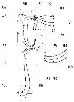
airflow then exits through discharge vent 101. A wedge-shaped baffle 88
protruding from the backside of the video monitor splits the air current into
upper and lower streams, both of which flow over and chill the backside of FPD
100. The upper air stream is drawn through fans 90 for recirculation. The
lower
air stream flows downwardly, and contacts baffle 86, which serves as a cold
air
turning vane, at the base of enclosure 40. The lower stream flows downwardly
towards the base of the enclosure, where baffle 86 channels the cool airflow
through the lower gap between the base of the FPD 100 and the enclosure. This
air current then flows upwardly through the gap between FPD 100 and the front
panel 50. As the airflow passes over the upper edge of FPD 100, it is drawn
through circulation fans 84, to be recirculated through ECU 74.
[0055] The present system is modular in structure, wherein each enclosure
40 may be separately assembled off site and shipped, along with the frame
members and other systems components, for on-site assembly. Assembly is
CA 02723676 2010-11-05
WO 2009/135308 PCT/CA2009/000629
-13-
relatively simple, with each individual enclosure 40 comprising a "plug and
play"
unit which need only be plugged into the power and video signal lines or a
wireless network.
[0056] Optionally, the display module 10 may be configured as a cubical or
rectangular structure or alternately individual video screen enclosures may be
mounted to a ceiling or floor. Other variations include back to back or side
by
side mounting, or surrounding a structural column.
[0057] Optionally, the enclosure includes an audio system (not illustrated).
In order to provide a clear audio output without the need for external
speakers,
a transducer is provided to effectively transform front panel 50 into a sound
driver. This may be provided, for example, with a PanasonicTM ambient speaker
system, in which a full range transducer type mechanism is attached directly
to
the from glass panel with an adhesive pad, attached directly to the internal
glass
face of the display. This permits a clear audio capability without the need
for
openings in the sealed enclosure.
[0058] Both open frame and finished commercial screens can be housed in
the enclosure. In one aspect, a high output LCD monitor, such as an MRI
brightness-enhanced open-frame 70" Samsung TM monitor is used, which is
effective in direct or near-direct sunlight. However, any suitable digital
screen
may be used in the system, and the existing screen within a unit may be
replaced or upgraded.
[0059] The present system may include hardware and software that
permits local or remote (web enabled) monitoring , control, and populating the
FCD with user selectable advertising material, which may include material
presented in display formats that are universally accepted and commonly used
in
the outdoor advertising industry.
[0060] The video and audio signals for the display strcuture 10 may
originate from a common source, to permit identical video images to be
displayed on all screens, or alternatively the displays and speakers may be
separately controlled. The signals may comprise pre-programmed signals, which
CA 02723676 2010-11-05
WO 2009/135308 PCT/CA2009/000629
-14-
may be provided by way of audio visual playback devices mounted within the
individual enclosures or within the interior of the display systems.
Alternatively,
the audio and/or audio-visual signals may be transmitted remotely, by wireless
or non-wireless means. The programming may be either pre-programmed, for
example displaying advertisements on a continuous loop, or may be remotely
programmed by manual or automatic control. Remotely sourced signals may be
transmitted to the displays by any suitable means including wireless
transmission or fibre optic transmission means. All such means for supplying
visual or audio-visual signals to the system are contemplated within the scope
of
this invention and would be known to persons of ordinary skill in the art.
[0061] The structure 10 may include a player module 600, comprising a
hardened computer unit and associated hard drive which together control the
digital content displayed on the FPD's 100. The player module communicates
with a remote command centre. This enables content selected at one or more
remote centres to be displayed on the screen. The player module may store
such data temporarily. The player module also functions as a monitoring unit,
to
signal local conditions and data back to the command centres, such as the
correct functioning of the display screen. By way of non-limited examples, the
system permits users to customize the display of advertising content which can
be controlled with user selectable criteria, such as the physical location of
the
device, the time and date, point of sale data, and product inventory
information.
In addition the player can be used to facilitate local communication with
devices,
such as, but not limited to, hand-held IR remotes, for local data input or for
set-
up or maintenance purposes. Further, it may also be used to relay audience
conditions at the local site to the command centres. The remote command may
be situated at one or more locations, or from sites on the Internet or a
private
data network, or even from mobile sites with access to such computer networks.
The communication method between the Player and the remote command centre
can be any high speed digital communication media, such as but not limited to,
hard-wired Ethernet, wireless Internet, broadband-over-power, fiber, etc. The
communication interface may be a separate module, or may be incorporated into
the player module.
CA 02723676 2010-11-05
WO 2009/135308 PCT/CA2009/000629
-15-
[0062] Optionally, at least one of the sides of the system consists of or
includes a backlit poster-type display in place of an enclosure 40.
[0063] According to a second embodiment, shown in Figure 9, one or more
enclosures 40 can be incorporated within a transit shelter 102. In this
aspect,
posts 20 may provide structural support for the shelter, thus integrating the
video display with the shelter. The video system thus provides both structural
support and shelter from the elements, in addition to the video display.
[0064] Figure 10 illustrates a third embodiment consisting of a single or
double-sided floor-standing (street-level) display 104 composed of either a
single enclosure 40, or dual enclosures 40 arranged back-to-back. Figure 11
illustrates a fourth embodiment, consisting of a one-sided, wall-mounted
display
106. Figure 12 illustrates a fifth embodiment, consisting of a two-sided,
ceiling
mounted display 108. The preceding systems of Figures 10-12 comprise one or
two enclosures 40 as generally described above, wherein the enclosures are
mounted within a frame 110 which supports the enclosure(s) in a suitable
configuration.
[0065] A sixth embodiment is shown in Figures 13-22. In this version,
enclosure 40 is adapted for maintaining a suitable operating temperature
within
its interior without the need for active cooling by an air conditioner or
other heat
exchanger, by generating a flow of ambient air through the enclosure. The
enclosure consists of front and rear housings 200 and 210 which open like a
clamshell, connected together with a removable hinged connection means,
described below in more detail. Rear housing 210 encloses the FPD 100 and the
ventilation components described herein, and front housing 200 includes the
clear viewing panel 50. A pliable gasket where housings 200 and 210 meet
provides a watertight seal.
[0066] The hinged connection means between the housings 200 and 210 is
disposed horizontally along their respective upper edges to permit the front
housing to swing away from the rear housing. The connection consists of
opposed mutually engaging flanges 212 and 214. A first flange 212 extends
forwardly from rear housing 210 with an outer portion which projects upwardly.
CA 02723676 2010-11-05
WO 2009/135308 PCT/CA2009/000629
-16-
Flange 214 extends rearwardly from the front housing 200 with an outer portion
which projects downwardly. The respective flanges engage each other to
suspend front housing 200 in a manner that permits front housing 200 to pivot
outwardly from rear housing 210 about a horizontal axis. The respective
flanges
interlock to prevent the housings from coming apart, and to lock the housings
together when the enclosure is closed. When enclosure 40 is open, the
respective flanges may be disengaged from each other by lifting the front
housing 200, thereby disengaging the mating flanges.
[0067] The front housing 200 is further attached to the rear housing 210
with a pair of gas spring struts 216, one on either side of the front housing
200
(see Figure 21). Struts 216 are provided with quick release attachment
members 218 where they join to the front housing, so that the front housing
200
can be fully disconnected from the rear housing 210, for example to replace
the
glass panel 50. Struts 216 are telescoping to permit the front housing to
open,
and are provided with sufficient resistance to hold to the front housing in
the
open position when required.
[0068] FPD 100 is retained within a screen holder 220, seen in more detail
in Figures 18-20, which in turn is mounted within the rear housing 210. The
screen holder is configured to also channel airflow within the enclosure for
ventilation of the FPD. Screen holder 220 comprises the following components:
a) a rectangular inner frame 222 dimensioned to fit a selected FPD. The
inner frame comprises four frame members 222a-d consisting of inwardly-facing
channel shaped members to receive the edges of the FPD. The frame members
are assembled together with corner brackets 223 that fasten to frame members
222 with screws or other fastening means, to permit assembly around FPD 100.
Frame members 222a-d effectively wrap around the periphery of FPD 100,
slightly overlapping the front face thereof. Each frame member 222 also
overlaps the rear face of FPD 100, and terminates in a flange 224 which
protrudes rearwardly and includes a vertical portion.
b) a rear panel 226, having ventilation slots 228 extending horizontally
therethrough. The rear panel 226 is mounted to flanges 224 so as to space the
rear panel from the rear face of FPD 100.
CA 02723676 2010-11-05
WO 2009/135308 PCT/CA2009/000629
-17-
c) an outer frame 230 which fastens to the rear panel 226, and when
mounted to the inner frame 222 via the attachment of the rear panel is spaced
from the inner frame. The outer frame 230 is composed of four outer channel-
shaped outer frame members 230a-d (only 230a-c are shown). The outer faces
232 of frame members 230 contact panel 50 when the enclosure is closed. As
well, the outer frame is configured to channel an airflow around FPD 100 to
provide ventilation.
[0069] As seen in Figure 22, screen holder 220 is retained within rear
housing 210 in a fashion which permits it to pivot outwardly from the rear
housing to permit access to the interior of the rear housing. The axis of
rotation
of screen holder 220 is horizontal and is parallel to the axis of rotation of
the
front housing. The retention of screen holder 220 is via mutually engaging
surfaces which operate in a fashion similar in principle to the engaging
flanges
holding the front and rear housings together, whereby the screen holder is
suspended from the rear housing by means of mutually engaging flanges 240
and 242. Flange 240 projects forwardly from the rear housing and upwardly,
and flange 424 projects rearwardly from the front housing and downwardly.
The respective flanges engage each other to suspend screen holder 220 in a
pivotal engagement with the rear housing 210, while permitting release of the
screen holder by lifting the screen housing to disengage the respective
flanges.
[0070] When front housing 200 is opened, FPD 100 may be swung
outwardly for access to the rear of the housing. The screen is further
fastened
to rear housing 210 with a pair of gas spring struts 244 which connect the
rear
panel 226 of screen holder 220 to rear housing 210. Struts 244 attach to
screen
holder 220 with quick-release mounts 246 to permit FPD 100 to be readily
detached for replacement.
[0071] Front housing 200 locks to the rear housing 210 in the closed
position to prevent unauthorized access, with a robust lock that resists
tampering.
[0072] The system includes an environmental control unit ("ECU") 300,
which is shown together with its associated components in Figures 13-17, 21
CA 02723676 2010-11-05
WO 2009/135308 PCT/CA2009/000629
-18-
and 22. ECU 300 is housed in the rear compartment 210 behind the FPD, within
an ECU compartment 302. ECU compartment 302 is defined by a wall 303
which maintains airflow separation between the incoming air entering the ECU
compartment, and the outgoing exhaust air exiting the enclosure 40. Wall 303
extends horizontally across the interior of the enclosure 40 so as to
effectively
surround the ECU. Exterior (ambient) air enters compartment 303 through
perforations 304 within the rear panel 306 of the enclosure. An inlet manifold
307 within ECU compartment 302 covers the perforated region. Inlet manifold
307 houses a semi-permeable membrane 308, such as a Gore TM membrane that
filters the incoming air to block liquid, particulates, etc., while permitting
the
inflow of air, thereby limiting the intake of moisture and contaminants into
the
enclosure.
[0073] The enclosure is configured to permit air circulation around the FPD
to control its temperature within a useable range. As seen in particular in
Figures 14 and 15, internal air circulation is driven in part by the venting
of
exhaust air from the enclosure, by exhaust fans 310 mounted within the rear
housing, located near the top thereof to take advantage of heat stratification
within the enclosure. Exhaust fans 310 are each housed within an exhaust
manifold 311 located at an upper corner of the rear housing. Internal air
circulation is further driven by an air circulation fan 312 located within a
heater/blower unit 320, which in turn is mounted within the ECU compartment
302. The heater/blower unit 320 includes an air intake 324 adjacent to the
intake manifold 306 to draw air into the enclosure. Air is discharged from the
heater/blower unit 320 through an air outlet 326 adjacent to the rear panel
226
of screen holder 220 to discharge air into the interior thereof. The
heater/blower
unit 320 comprises a variable speed, high capacity unit, which when operating
draws air into the ECU enclosure from the intake manifold 306.
[0074] A portion of the incoming airflow enters the heater/blower unit
while the remainder of the airflow is directly circulated into the enclosure
40
without entering the heater/blower unit. Exhaust fans 310 provide additional
air
circulation by withdrawing heated air from the enclosure. The airflow from
both
paths is then channeled into screen holder 220, through the openings in the
rear
CA 02723676 2010-11-05
WO 2009/135308 PCT/CA2009/000629
-19-
panel thereof. The airflow within the screen holder follows two paths, the
first
being under and around the front of FPD 100, and the second path being
upwardly along the rear face of the FPD. Both air streams are channeled
between the inner and outer FPD frames 222 and 230, which are spaced apart to
provide an airflow channel. Outer frame members 230a-d effectively form
baffles which channel the airflow around FPD 100.
[0075] ECU enclosure compartment 302 includes an exhaust manifold 311.
The air streams circulating around FPD 100 are channeled out of enclosure 40
through outlet openings 330 within rear panel 226, which feeds into manifold
311. Exhaust fans 310 discharge the heated air from the exhaust manifold 311
into the ambient air.
[0076] Air circulation through enclosure 40 is shown by the arrows in
Figure 14, wherein ambient air enters the inlet manifold 306, and passes
through membrane 308 into ECU compartment 302. A portion of the ambient
air exits compartment 302 directly through openings 228 in the screen
enclosure
220, and the remaining portion passes through heater/blower unit 320, where
the air is optionally heated (if required) and accelerated by fan 312. The
combined airstreams enter the screen enclosure 220, where a portion travels
upwardly within the space between the rear surface of the FPD 100 and the rear
panel 226 of the screen enclosure. The remaining ambient airflow is deflected
around the bottom edge of the FPD and travels upwardly across the front face
of
the FPD. The respective airflows then enter the exhaust manifold 311, where
they are vented by fan 310 out of the enclosure. Figure 15 represents airflow
through the enclosure, showing in particular the laminar flow achieved across
the front and rear faces of FPD 100.
[0077] The heater component within the heater/blower unit 320 is a
variable electrical resistance heater, and is particularly useful if the unit
is
intended to operate in a cold climate. For use in a consistently warm
environment (such as an indoor or temperature environment) the heater may be
dispensed with.
CA 02723676 2010-11-05
WO 2009/135308 PCT/CA2009/000629
-20-
[0078] Operation of the control system of ECU 300 is illustrated
schematically in Figure 26. ECU derives AC current from the mains feed. AC
power passes from ECU 300 and is supplied as both DC and AC power, to
components in the system. ECU 300 includes processor 500 that comprises
firmware responsive to integral and attached external sensors. The ECU
firmware includes integrated charts with user changeable fields to set the
temperatures at which the system elements are switched. The firmware charts
control the following components:
a) the on/off temperatures of equipment connected to the AC outputs
b) the on/off temperature of heating elements in the system
c) the on/off temperature settings and run-speed of exhaust cooling
fans.
[0079] ECU 300 includes a data connection to the content player, preferably a
Mini IPX PC, with the data connection comprising an RS232 port for the
transfer of
data signals from the processor.
[0080] ECU 300 can be interrogated, remotely via the data connection, from
the content player, using a "read ECU" command to view firmware charts
controlling
the operation of the system.
[0081] According to a preferred control setting, the firmware is programmed to
control the heater and fans in response to the internal temperature within the
enclosure as follows:
Temp -40C -30C -20C -10C 0C 10C 20C 30C 40C
Heater ON ON ON ON ON OFF OFF OFF OFF
Fans OFF OFF OFF OFF OFF OFF ON ON ON
20% 50% 100%
[0082] The firmware is programmed to turn power to the FPD off if the internal
temperature is outside the above range.
CA 02723676 2010-11-05
WO 2009/135308 PCT/CA2009/000629
-21-
[0083] According to one embodiment, the architecture of the ECU and
electronic componentry is as follows:
1. Power Input
= AC mains supply feed 110V to 250V
= Main power switch - system disconnect
= Convenience outlet for peripheral equipment - optional
2. ECU - System Control Board
= AC Power feed from system disconnect switch
= AC Power distribution to all integrated equipment power supplies
= System sensors on the board, and connections for remote sensors
by cable to various positions within the enclosure (temperature,
shock/acceleration; ambient light, enclosure intrusion/security),
with ECU being responsive to signals from said sensors to shut
down power to said FPD or transmit an alarm signal to a remote
recipient
= AC power distribution and (on/off) control, heating elements
= DC power distribution and (speed) control system (exhaust) fans
= Alarm reporting function to content player
3. Power Supply or Supplies
= Integrated player board AC/DC
= LCD backlight AC/DC
4. Environmental Control - System Enclosure
= Fan heater appliance to maintain enclosure internal ambient
temperature within given parameters, determined by ECU firmware
= Speed controlled high capacity exhaust fans to remove excess heat
and maintain enclosure internal ambient temperature within given
parameters, determined by ECU firmware
5. Electronic Equipment
= Content player - Mini IPX format, ruggedized PC board, with video
output to display(s) and network connection
= Data storage device(s)
= Wireless adapter (optional)
= Network device(s)
CA 02723676 2010-11-05
WO 2009/135308 PCT/CA2009/000629
-22-
6. Display(s)
= LCD module with integrated backlight and T-con board LVDS
connection
= Screen driver board with video feed from content player [may be
eliminated if LVDS direct feed from player is available]
[0084] A seventh embodiment is shown in Figures 23-25, in which the
enclosure 400 includes vertical spaced apart lateral sidewalls 401, having
downwardly extending feet 402 (seen in Figs. 24 and 25). Opposed bottom and
top walls 404 and 406 and a rear panel 408 are fastened to the sidewalls 401
to
define an interior space. The rear panel 408 is removable, and gasket 409
seals
rear panel 408 to walls 404 and 406 and sidewalls 406. An FPD housing 410
installed within enclosure 400, with a gasket 414 providing a resilient seal
where
the FPD housing contacts the enclosure. The FPD housing 410 is hinged to
enclosure 400 with mutually engaging flanges 500 and 502 in the same manner
as described above in connection with the 6th embodiment hereof. When
closed, the FPD housing fits within the interior of enclosure 400.
[0085] The FPD housing 410 includes a bottom wall 405. An air inlet
418, provides air access to the FPD housing through a slotted portion of the
bottom wall. The air inlet is covered with an inlet plenum 422, which houses a
semi-permeable membrane 420 to filter the incoming air as described above.
The inlet plenum 422 is retained by a removable clamp 423. An air outlet 424
is
provided within the upper wall 407 in a location opposed to inlet plenum 422
to
receive the outflow of air from the enclosure.
[0086] A battery of exhaust fans 426 is mounted to the top wall 406 of
enclosure 400. Top wall 406 includes an array of outlet openings 430 aligned
with exhaust fans 426. Outlets 430 are aligned with and directly above outlet
424, to exhaust air from the interior of FPD housing 410. A heater core 432 is
mounted to the rear panel 408 within the interior of outer enclosure 400 to
provide additional heat, when necessary. Heater core 432 comprises an
electrical resistance heater, as described above. Airflow within enclosure 400
is
further driven by a battery of circulation fans 440, mounted in a vertical row
within the interior of the enclosure. Circulation fans 440 are mounted on a
CA 02723676 2010-11-05
WO 2009/135308 PCT/CA2009/000629
-23-
vertical fan bracket 442, which mounts to the heater core 432. Circulation
fans
440 function in a similar fashion to circulation fans 84 described above.
[0087] The airflow entering the enclosure is directed to flow over and
around the FPD so as to maintain its temperature within the desired operating
range. The fans, heating system and other active system components are
controlled by the EDU as described above.
[0088] One or more FPD power supplies 450, system controller 452, and
other electrical components are mounted to the rear panel within the interior
of
the enclosure.
[0089] The enclosure 400 of the seventh embodiment may be fitted within
a video display module of any of the embodiments described above, including
without limitation a multi-sided free standing display that incorporates
multiple
enclosures, or a mounted display unit. An audio system may be incorporated,
as described above, and the images on FPD may be supplied by an on-site
source or supplied remotely in the manner described above.
[0090] The present invention encompasses variations and departures from
the detailed embodiments described herein. The full scope of the invention
includes the present disclosure of the invention, including the detailed
description of embodiments, as well as the invention as set forth in the
accompanying claims, and all functional and mechanical equivalents of any
elements described herein.