Note: Descriptions are shown in the official language in which they were submitted.
CA 02723864 2016-01-27
HOT-FILL CONTAINER
TECHNICAL FIELD
[0002]
This disclosure generally relates to plastic containers for
retaining a commodity, such as a solid or liquid commodity. More specifically,
this disclosure relates to a one-piece blown container having a series of
horizontal ribs designed to achieve optimal performance with regard to vacuum
absorption, top load strength capabilities and dent resistance.
BACKGROUND
[0003]
As a result of environmental and other concerns, plastic
containers, more specifically polyester and even more specifically
polyethylene
terephthalate (PET) containers are now being used more than ever to package
numerous commodities previously supplied in glass containers. Manufacturers
and fillers, as well as consumers, have recognized that PET containers are
lightweight, inexpensive, recyclable and manufacturable in large quantities.
[0004]
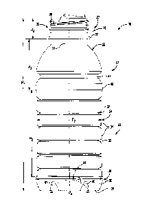
Blow-molded plastic containers have become commonplace
in packaging numerous commodities. PET is a crystallizable polymer, meaning
that it is available in an amorphous form or a semi-crystalline form. The
ability of
a PET container to maintain its material integrity relates to the percentage
of the
PET container in crystalline form, also known as the "crystallinity" of the
PET
container. The following equation defines the percentage of crystallinity as a
volume fraction:
¨
% Crystallinity = ( P P. )x100
P, ¨Pa
1
CA 02723864 2010-11-08
WO 2009/140335 PCT/US2009/043714
where p is the density of the PET material; pa is the density of pure
amorphous
PET material (1.333 g/cc); and pc is the density of pure crystalline material
(1.455 g/cc).
[0005]
Container manufacturers use mechanical processing and
thermal processing to increase the PET polymer crystallinity of a container.
Mechanical processing involves orienting the amorphous material to achieve
strain hardening. This processing commonly involves stretching an injection
molded PET preform along a longitudinal axis and expanding the PET preform
along a transverse or radial axis to form a PET container. The combination
promotes what manufacturers define as biaxial orientation of the molecular
structure in the container. Manufacturers of PET containers currently use
mechanical processing to produce PET containers having approximately 20%
crystallinity in the container's sidewall.
[0006]
Typically, an upper portion of the plastic container defines
an opening. This upper portion is commonly referred to as a finish and
includes
some means for engaging a cap or closure to close off the opening. In the
traditional injection-stretch blow molding process, the finish remains
substantially
in its injection molded state while the container body is formed below the
finish.
The finish may include at least one thread extending radially outwardly around
an annular sidewall defining a thread profile. In one application, a closure
member or cap may define a complementary thread, or threads, that are
adapted to cooperatively mate with the threads of the finish.
[0007] In
some applications, plastic containers must withstand
extreme temperatures and pressures, while providing an improved heat
resistance and an ability to withstand vacuum forces at a reduced weight as
compared to traditional designs. In
other examples, conventional plastic
containers that are cylindrical in profile, do not include a sidewall design
with
adequate vertical load bearing and dent resistance capabilities and
properties.
[0008]
Thus, there is a need for a plastic container design having a
sidewall capable of achieving optimal performance with regard to vacuum
absorption, top load strength capabilities and dent resistance.
2
CA 02723864 2010-11-08
WO 2009/140335 PCT/US2009/043714
SUMMARY
[0009] A
one-piece plastic container according to the present
disclosure defines a container body, and includes an upper portion having a
finish. Integrally formed with the finish and extending downward therefrom is
a
shoulder region. The shoulder region merges into and provides a transition
between the finish and a sidewall portion. The sidewall portion extends
downward from the shoulder region to a base portion having a base. The
sidewall portion can define a series of horizontal lands and horizontal ribs.
The
horizontal lands and horizontal ribs can extend continuously in a vertical
direction from the shoulder region to the base portion.
[0010]
According to yet other features, the finish defines a means
for attaching a closure thereon. The means for attaching a closure includes at
least one thread. The container is composed of polyethylene terephthalate. The
sidewall portion and the base portion are biaxially oriented.
[0011] Additional
benefits and advantages of the present disclosure
will become apparent to those skilled in the art to which the present
disclosure
relates from the subsequent description and the appended claims, taken in
conjunction with the accompanying drawings. It will also be appreciated by
those skilled in the art to which the present disclosure relates that the
container
of the present disclosure may be manufactured utilizing alternative blow
molding
processes to those disclosed.
BRIEF DESCRIPTION OF THE DRAWINGS
[0012]
FIG. 1 is a side elevational view of a one-piece plastic
container constructed in accordance with the teachings of the present
disclosure.
[0013]
FIG. 2 is a side view of the one-piece plastic container of
FIG. 1.
[0014]
FIG. 3 is a bottom elevational view of the one-piece plastic
container of FIG. 1.
[0015] FIG. 4 is a
bottom view of the one-piece plastic container of
FIG. 1.
3
CA 02723864 2010-11-08
WO 2009/140335 PCT/US2009/043714
[0016]
FIG. 5 is a sectional view of an exemplary mold cavity used
during formation of the container of FIG. 1 and shown with a preform
positioned
therein.
[0017]
FIG. 6 is an enlarged side view of a single horizontal rib
within the sidewall of the one-piece plastic container of FIG. 1; and
[0018]
FIG. 7 is an enlarged side view of the sidewall of the one-
piece plastic container of FIG. 1 comparing an empty container versus a hot-
filled, capped and cooled container.
DETAILED DESCRIPTION
[0019]
The following description is merely exemplary in nature, and
is in no way intended to limit the disclosure or its application or uses.
[0020]
FIGS. 1-4, 6 and 7 show one preferred embodiment of the
present container. In the Figures, reference number 10 designates a one-piece
plastic, e.g. polyethylene terephthalate (PET), container. The plastic
container
10 can define a longitudinal axis L (FIG. 2) and be substantially cylindrical
in
cross section. In this particular embodiment, the plastic container 10 has a
volume capacity of about 20 fl. oz. (591 cc). Those of ordinary skill in the
art
would appreciate that the following teachings of the present disclosure are
applicable to other containers, such as rectangular, triangular, hexagonal,
octagonal or square shaped containers, which may have different dimensions
and volume capacities. It is also contemplated that other modifications can be
made depending on the specific application and environmental requirements.
[0021] As
shown in FIG. 1, the one-piece plastic container 10
according to the present teachings defines a container body 12, and includes
an
upper portion 14 having a finish 20. Integrally formed with the finish 20 and
extending downward therefrom is a shoulder region 22. The shoulder region 22
merges into and provides a transition between the finish 20 and a sidewall
portion 24. The sidewall portion 24 extends downward from the shoulder region
22 to a base portion 28 having a base 30. The sidewall portion 24 can define a
series of horizontal lands 31 and horizontal ribs 32. The horizontal lands and
4
CA 02723864 2010-11-08
WO 2009/140335 PCT/US2009/043714
horizontal ribs 31 and 32, respectively can extend continuously in a vertical
direction from the shoulder region 22 to the base portion 28.
[0022] A
neck 33 may also be included having an extremely short
height, that is, becoming a short extension from the finish 20, or an
elongated
height, extending between the finish 20 and the shoulder region 22. A support
ring 34 can be defined on the neck 33. The finish 20 further includes a
threaded
region 36 having at least one thread 38 formed on an annular sidewall 40. The
threaded region 36 provides a means for attachment of a similarly threaded
closure or cap (not shown). The cap can define at least one thread formed
around an inner diameter for cooperatively riding along the thread(s) 38 of
the
finish 20. Alternatives may include other suitable devices that engage the
finish
of the plastic container 10. Accordingly, the closure or cap engages the
finish
20 to preferably provide a hermetical seal of the plastic container 10. The
closure or cap is preferably of a plastic or metal material conventional to
the
15
closure industry and suitable for subsequent thermal processing, including
high
temperature pasteurization and retort. A transition rib 41 and a transition
land 42
can be defined on the sidewall portion 24 and marks a transition between the
shoulder region 22 and a label panel area 43. The label panel area 43
therefore,
can be defined between the transition land 42 and the base portion 28. It is
20
appreciated that because the plastic container 10 incorporates the transition
rib
41 and the transition land 42, the series of horizontal lands 31 and
horizontal ribs
32 can extend continuously from the transition land 42 to the base portion 28.
[0023]
The plastic container 10 may include as few as three (3)
horizontal ribs 32 and as many as nine (9) horizontal ribs 32. As shown in
FIG.
6, horizontal ribs 32 further include an upper wall 45 and a lower wall 46
separated by an inner curved wall 47. Inner curved wall 47 is in part defined
by
a relatively sharp innermost radius r1. Preferably, sharp innermost radius r1
lies
within the range of about 0.01 inches to about 0.03 inches. The relatively
sharp
innermost radius r1 of inner curved wall 47 facilitates improved material flow
during blow molding of the plastic container 10 thus enabling the formation of
relatively deep horizontal ribs 32.
5
CA 02723864 2010-11-08
WO 2009/140335 PCT/US2009/043714
[0024]
Horizontal ribs 32 each further include an upper outer radius
r2 and a lower outer radius r3. Preferably both the upper outer radius r2 and
the
lower outer radius r3 each lie within the range of about 0.07 inches to about
0.14
inches. The upper outer radius r2 and the lower outer radius r3 may be equal
to
each other or differ from one another. Preferably the sum of the upper outer
radius r2 and the lower outer radius r3 will be equal to or greater than about
0.14
inches and less than about 0.28 inches.
[0025] As
shown in FIG. 6, horizontal ribs 32 further include an
upper inner radius r4 and a lower inner radius r5. The upper inner radius r4
and
the lower inner radius r5 each lie within the range of about 0.08 inches to
about
0.11 inches. The upper inner radius r4 and the lower inner radius r5 may be
equal to each other or differ from one another. Preferably the sum of the
upper
inner radius r4 and the lower inner radius r5 will be equal to or greater than
about
0.16 inches and less than about 0.22 inches.
[0026] Horizontal
ribs 32 have a rib depth RD of about 0.12 inches
and a rib width RW of about 0.22 inches as measured from the upper extent of
the upper outer radius r2 and the lower extent of the lower outer radius r3.
As
such, horizontal ribs 32 each have a rib width RW to rib depth RD ratio. The
rib
width RW to rib depth RD ratio is preferably in the range of about 1.6 to
about
2Ø
[0027]
Horizontal ribs 32 are designed to achieve optimal
performance with regard to vacuum absorption, top load strength and dent
resistance. Horizontal ribs 32 are designed to compress slightly in a vertical
direction to accommodate for and absorb vacuum forces resulting from hot-
filling, capping and cooling of the container contents. Horizontal ribs 32 are
designed to compress further when the filled container is exposed to excessive
top load forces.
[0028] As
shown in FIG. 7, the above-described horizontal rib 32
radii, walls, depth and width in combination form a rib angle A. The rib angle
A
of an unfilled plastic container 10 may be about 58 degrees. After hot-
filling,
capping and cooling of the container contents, the resultant vacuum forces
cause the rib angle A to reduce to about 55 degrees (shown in phantom in FIG.
6
CA 02723864 2010-11-08
WO 2009/140335 PCT/US2009/043714
7). This represents a reduction of the rib angle A of about 3 degrees as a
result
of vacuum forces present within the plastic container 10 representing a
reduction
in the rib angle A of about 5%. Preferably, the rib angle A will be reduced by
at
least about 3% and no more than about 8% as a result of vacuum forces.
[0029] After
filling, it is common for the plastic container 10 to be
bulk packed on pallets. Pallets are then stacked atop one another resulting in
top load forces being applied to the plastic container 10 during storage and
distribution. Thus, horizontal ribs 32 are designed so that the rib angle A
may be
further reduced to absorb top load forces. However, horizontal ribs 32 are
designed so that the upper wall 45 and the lower wall 46 never come into
contact
with each other as a result of vacuum or top load forces. Instead horizontal
ribs
32 are designed to allow the plastic container 10 to reach a state wherein the
plastic container 10 is supported in part by the product inside when exposed
to
excessive top load forces thereby preventing permanent distortion of the
plastic
container 10. In addition, this enables horizontal ribs 32 to rebound and
return
substantially to the same shape as before the top load forces were applied,
once
such top load forces are removed.
[0030]
Horizontal lands 31 are generally flat in vertical cross-
section as molded. When the plastic container 10 is subjected to vacuum and/or
top load forces, horizontal lands 31 are designed to bulge slightly outward in
vertical cross-section to aid the plastic container 10 in absorbing these
forces in
a uniform way.
[0031]
The plastic container 10 has been designed to retain a
commodity. The commodity may be in any form such as a solid or liquid
product. In one example, a liquid commodity may be introduced into the
container during a thermal process, typically a hot-fill process. For hot-fill
bottling applications, bottlers generally fill the plastic container 10 with a
liquid or
product at an elevated temperature between approximately 155 F to 205 F
(approximately 68 C to 96 C) and seal the plastic container 10 with a cap or
closure before cooling. In addition, the plastic container 10 may be suitable
for
other high-temperature pasteurization or retort filling processes or other
thermal
7
CA 02723864 2010-11-08
WO 2009/140335 PCT/US2009/043714
processes as well. In another example, the commodity may be introduced into
the plastic container 10 under ambient temperatures.
[0032]
The plastic container 10 of the present disclosure is an
injection-stretch blow molded, biaxially oriented container with a unitary
construction from a single or multi-layer material. A well-known stretch-
molding,
heat-setting process for making the one-piece plastic container 10 generally
involves the manufacture of a preform 44 (FIG. 5) of a polyester material,
such
as polyethylene terephthalate (PET), having a shape well known to those
skilled
in the art similar to a test-tube with a generally cylindrical cross section
and a
length typically approximately fifty percent (50%) that of the resultant
container
height. In one example, the preform 44 can be injection molded. As will be
appreciated, the upper portion 14 remains substantially unchanged from its
preform state while the container body 12 is formed below the finish 20. An
exemplary method of manufacturing the plastic container 10 will be described
in
detail below.
[0033]
Turning specifically now to FIG. 2, exemplary dimensions for
the plastic container will be described. It is appreciated that other
dimensions
may be used. The plastic container 10 has an overall height H1 of about 187.65
mm (7.39 inches). A height H2 of the label panel area 43 may be 89.45 mm
(3.52 inches). A height H3 taken from the top of the label panel area 43 and
the
bottom of the support ring 34 may be 65.52 mm (2.58 inches). A height H4 taken
from the bottom of the support ring 34 and the top of the plastic container 10
may be 18.31 mm (0.72 inches). A diameter D1 taken at the widest portion of
the base portion 28 may be 74.22 mm (2.92 inches). A diameter D2 taken at
each of the horizontal lands 31 may be 73.48 mm (2.89 inches).
[0034]
With specific reference now to FIGS. 3 and 4, the base
portion 28 will be described in detail. The base portion 28 defines a radial
sidewall 50 that transitions between the sidewall portion 24 and the base 30.
The base 30 defines a continuous contact surface 52 defined generally between
the radial sidewall 50 and a central pushup portion 54. A plurality of facets
60
are defined at a transition between the radial sidewall 50 and the continuous
contact surface 52. The facets 60 can be generally linear. The continuous
8
CA 02723864 2010-11-08
WO 2009/140335 PCT/US2009/043714
contact surface 52 is generally planar and defines a contact surface area 70
for
supporting the plastic container 10 in an upright position. The central pushup
portion 54 defines a plurality of radially arranged support ridges 74. The
radially
arranged support ridges 74 centrally converge toward a nub 76. As illustrated
in
FIG. 2, the central pushup portion 54 can define a diameter D4 of 57.15 mm
(2.25 inches). A plurality of modulating vertical detent ribs 80 are defined
on the
base portion 28 generally at a transition between the continuous contact
surface
52 and the sidewall portion 24. While the example shown illustrates six (6)
detent ribs 80, more or fewer detent ribs 80 may be formed on the base portion
28.
[0035]
The detent ribs 80 are formed at a transition between
adjacent facets 60. As a result, an otherwise sharp transition between
adjacent
facets 60 is de-emphasized. The resultant base portion 28 provides improved
base stiffness (such as in the vertical direction) and strength of the plastic
container 10 as a whole.
[0036]
The plastic container 10 molded with the geometrical
relationships according to the instant disclosure can be produced on high-
speed
blow-molding production platforms without compromising the functionality of
the
base portion 28 or the resultant plastic container 10 as a whole.
[0037] In one
example, a machine (not illustrated) places the
preform 44 heated to a temperature between approximately 190 F to 250 F
(approximately 88 C to 121 C) into a mold cavity 81 (see FIG. 5). The mold
cavity 81 may be heated to a temperature between approximately 250 F to
350 F (approximately 121 C to 177 C). A stretch rod apparatus (not
illustrated)
stretches or extends the heated preform 44 within the mold cavity 81 to a
length
approximately that of the resultant plastic container 10 thereby molecularly
orienting the polyester material in an axial direction generally corresponding
with
the central longitudinal axis L of the plastic container 10. Again, during the
stretching process, the finish 20 remains unchanged in an injection molded
state
while the container body 12 is formed below the finish 20. While the stretch
rod
extends the preform 44, air having a pressure between 300 PSI to 600 PSI (2.07
MPa to 4.14 MPa) assists in extending the preform 44 in the axial direction
and
9
CA 02723864 2010-11-08
WO 2009/140335 PCT/US2009/043714
in expanding the preform 44 in a circumferential or hoop direction thereby
substantially conforming the polyester material to the shape of the mold
cavity 81
and further molecularly orienting the polyester material in a direction
generally
perpendicular to the axial direction, thus establishing the biaxial molecular
orientation of the polyester material in most of the plastic container 10. The
pressurized air holds the mostly biaxial molecularly oriented polyester
material
against a mold surface 82 of the mold cavity 81 for a period of approximately
two
(2) to five (5) seconds before removal of the plastic container 10 from the
mold
cavity 81. This process is known as heat setting and results in a heat-
resistant
container suitable for filling with a product at high temperatures. The
disclosed
sidewall configuration improves ease of manufacture and results in more
consistent material distribution in the sidewall.
[0038] In
another example, a machine (not illustrated) places the
preform 44 heated to a temperature between approximately 185 F to 239 F
(approximately 85 C to 115 C) into the mold cavity 81. The mold cavity 81 may
be chilled to a temperature between approximately 32 F to 75 F (approximately
0 C to 24 C). A stretch rod apparatus (not illustrated) stretches or extends
the
heated preform 44 within the mold cavity 81 to a length approximately that of
the
resultant plastic container 10 thereby molecularly orienting the polyester
material
in an axial direction generally corresponding with the central longitudinal
axis L
of the plastic container 10. Again, during the stretching process, the finish
20
remains unchanged in an injection molded state while the container body 12 is
formed below the finish 20. While the stretch rod extends the preform 44, air
having a pressure between 300 PSI to 600 PSI (2.07 MPa to 4.14 MPa) assists
in extending the preform 44 in the axial direction and in expanding the
preform
44 in a circumferential or hoop direction thereby substantially conforming the
polyester material to the shape of the mold cavity 81 and further molecularly
orienting the polyester material in a direction generally perpendicular to the
axial
direction, thus establishing the biaxial molecular orientation of the
polyester
material in most of the plastic container 10. The pressurized air holds the
mostly
biaxial molecularly oriented polyester material against the mold surface 82 of
the
mold cavity 81 for a period of approximately two (2) to five (5) seconds
before
CA 02723864 2010-11-08
WO 2009/140335 PCT/US2009/043714
removal of the plastic container 10 from the mold cavity 81. This process is
utilized to produce containers suitable for filling with product under ambient
conditions or cold temperatures.
[0039] Alternatively, other manufacturing methods using other
conventional materials including, for example, high density polyethylene,
polypropylene, polyethylene naphthalate (PEN), a PET/PEN blend or copolymer,
and various multilayer structures may be suitable for the manufacture of the
plastic container 10. Those having ordinary skill in the art will readily know
and
understand plastic container manufacturing method alternatives.
[0040] While the above description constitutes the present
disclosure, it will be appreciated that the disclosure is susceptible to
modification,
variation and change without departing from the proper scope and fair meaning
of the accompanying claims.
11