Note: Descriptions are shown in the official language in which they were submitted.
CA 02724771 2010-11-15
WO 2009/140638 PCT/US2009/044212
DEVICES AND METHODS FOR TREATMENT OF ABDOMINAL
AORTIC ANEURYSMS
CROSS-REFERENCE TO RELATED APPLICATIONS
100011 This application is related to, and claims the benefit of U.S.
Provisional
61/053,378 filed May 15, 2008, the entirety of which is hereby incorporated by
reference
herein and made a part of the present specification.
BACKGROUND OF THE INVENTION
Field of the Invention
100021 This invention relates generally to a modular biluminal endograft
system
for treatment of circumscribed dilatation of a large blood vessel, such as the
abdominal aorta.
More particularly, the present invention relates to the method of reducing the
vessel diameter,
minimizing possibility of vessel rupture and generating multiple lumina for
down-stream
flow continuity.
Description of the Related Art
100031 The aorta delivers blood and oxygen to all arterial branches of the
body,
and as such is the largest artery of the human body. Based on the location of
any particular
segment in relation to the diaphragm, the aorta is referred to as thoracic or
abdominal. The
thoracic aorta if subdivided further into the ascending thoracic, that
contains the aortic root
and a tubular section containing the vessels leading to the brain, and the
descending thoracic
aorta. The abdominal aorta begins at the diaphragm and is terminal at the
aortoiliac
bifurcation where the arteries irrigating the lower limbs begin, and along its
course giving off
various visceral branches mesenteric arterial branches as well as the renal
arteries. The
diameter of the aorta varies along the different segments. The normal diameter
of the
thoracic aorta is in the order of about 3 cm at the tubular ascending portion,
2.5 cm at the
descending thoracic aorta and 2 cm in the infrarenal abdominal aorta. The
aortic dimensions
vary relatively to body surface area, age and gender, males having larger
aortic dimensions
than females.
-1-
CA 02724771 2010-11-15
WO 2009/140638 PCT/US2009/044212
100041 An enlargement of the aorta beyond its normal diameter is termed an
aneurysm. The term aneurysm means dilation or dilatation. A segment of the
aorta is termed
aneurismal if its maximal diameter is greater than 1.5 times that of the
adjacent proximal
normal segment. Aortic aneurysms are more common in the abdominal aorta, one
reason for
this is that elastin, the principal load bearing protein present in the wall
of the aorta, is
reduced in the abdominal aorta as compared to the thoracic aorta (nearer the
heart). Another
is that the abdominal aorta does not possess vasa vasorum which hinders
repair. Most are
true aneurysms that involve all three layers (tunica intima, tunica media and
tunica
adventitia), and are generally asymptomatic before rupture.
100051 The prevalence of abdominal aortic aneurysms (AAAs) increases with age,
with an average age of 65-70 at the time of diagnosis. AAAs have been
attributed to
atherosclerosis, though other factors are involved in their fonnation. An AAA
may remain
asymptomatic indefinitely. There is a large risk of rupture once the size has
reached 5 cm,
though some AAAs may swell to over 15 cm in diameter before rupturing. Before
rupture, an
AAA may present as a large, pulsatile mass above the umbilicus. A bruit may be
heard from
the turbulent flow in a severe atherosclerotic aneurysm or if thrombosis
occurs.
Unfortunately, however, rupture is usually the first hint of AAA. Once an
aneurysm has
ruptured, it presents with a classic pain-hypotension-mass triad. The pain is
classically
reported in the abdomen, back or flank. It is usually acute, severe and
constant, and may
radiate through the abdomen to the back.
100061 The diagnosis of an abdominal aortic aneurysm can be confirmed at the
bedside by the use of ultrasound. Rupture could be indicated by the presence
of free fluid in
potential abdominal spaces, such as Morrison's pouch, the splenorenal space,
subdiaphragmatic spaces and peri-vesical spaces. A contrast-enhanced abdominal
CT scan is
needed for confirmation. Only 10-25% of patients survive rupture due to large
pre- and post-
operative mortality. Annual mortality from ruptured abdominal aneurysms in the
United
States alone is about 15,000. Another important complication of AAA is
formation of a
thrombus in the aneurysm.
100071 The definitive treatment for an aortic aneurysm is surgical repair of
the
aorta. This typically involves opening up of the dilated portion of the aorta
and insertion of a
-2-
CA 02724771 2010-11-15
WO 2009/140638 PCT/US2009/044212
synthetic (Dacron or Gore-tex) patch tube. Once the tube is sewn into the
proximal and distal
portions of the aorta, the aneurysmal sac is closed around the artificial
tube. Instead of
sewing, the tube ends, made rigid and expandable by Nitinol wireframe, can be
much more
simply and quickly inserted into the vascular stumps and there permanently
fixed by external
ligature.
100081 In the recent years, the endoluminal treatment of abdominal aortic
aneurysms has emerged as a minimally invasive alternative to open surgery
repair. In
endovascular surgery, a synthetic graft (stent-graft consisting of a polyester
tube inside a
metal cylinder) is attached to the end of a thin tube (catheter) that is
inserted into the
bloodstream, usually through an artery in the leg. Watching the progress of
the catheter on an
X-ray monitor, the surgeon threads the stent-graft to the weak part of the
aorta where the
aneurysm is located. Once in place, the graft is expanded. The stent-graft
reinforces the
weakened section of the aorta to prevent rupture of the aneurysm. The metal
frame is
expanded like a spring to hold tightly against the wall of the aorta, cutting
off the blood
supply to the aneurysm. The blood now flows through the stent-graft, avoiding
the aneurysm.
The aneurysm typically shrinks over time. This technique has been reported to
have a lower
mortality rate compared to open surgical repair, and is now being widely used
in individuals
with co-morbid conditions that make them high risk patients for open surgery.
Some centers
also report very promising results for the specific method in patients that do
not constitute a
high surgical risk group.
100091 There have also been many reports concerning the endovascular treatment
of ruptured abdominal aortic aneurysms, which are usually treated with an open
surgery
repair due to the patient's impaired overall condition. Mid-term results have
been quite
promising. The continuous development of the available stent technology in
conjunction with
the growing experience of the vascular experts that apply the technique will
further enhance
its safety and efficacy in the years to come. However, according to the latest
studies, the
current stent-grafts and procedures do not carry any overall survival benefit.
100101 U.S. Pat. No. 5,676,697 issued on Oct. 14, 1997, entire contents of
which
are incorporated herein by reference, discloses an intraluminal graft for
installing an
intraluminal graft in relation to a bifurcation of a trunk vessel into two
branch vessels to
-3-
CA 02724771 2010-11-15
WO 2009/140638 PCT/US2009/044212
bypass an aneurysm defect or injury, wherein the intraluminal graft is formed
of two
cooperating graft prostheses.
[0011] The market today is populated by devices approximately 20F and greater
requiring the need for a surgical cut-down approach utilizing catheters,
guidewires and
accessory devices which substantially eliminate the need for open surgical
intervention.
Although the cut-down approach significantly reduces the acute complications
that often
accompany open surgical intervention, the ultimate goal and the market trend
is to reduce
delivery system profiles and to be able to perform the procedure of delivering
an endograft
percutaneously, which eliminates the need for the cut-down procedure. There is
a clinical
need for addressing the endoleak and device anchoring/migration issues to
benefit the AAA
patient with new product design and features with a modular biluminal
endograft system.
SUMMARY OF THE INVENTION
[0012] The present invention overcomes the disadvantages associated with
larger
endograft as briefly described above.
100131 In accordance with preferred embodiments of the present invention, some
aspects of the invention relate to a modular biluminal endograft system for
treatment of
circumscribed dilatation of a large blood vessel, such as the abdominal aorta.
One aspect of
the present invention relates to the method of reducing the vessel diameter,
minimizing
possibility of vessel rupture and generating multiple lumina for down-stream
flow continuity.
[0014] Some aspects of the invention provide a flexible or shapeable stent
graft
for inserting into a blood vessel, comprising a distal section, a proximal
section and a graft
body connecting the distal and proximal sections, the graft having an inner
layer of water-
tight flexible tube, a middle layer of semi-rigid or rigid material, and an
outer layer of water-
tight flexible overlap, wherein the graft is characterized with at least two
water-tight layers.
In one embodiment, the stent graft only has the middle layer and outer layer.
In another
embodiment, the middle layer comprises semi-rigid or rigid material in mesh-
like or spiral
configuration.
[0015] Some aspects of the invention provide a radially expandable sheath as a
guiding sheath, comprising a continuous integral sheath body that is radially
expandable
-4-
CA 02724771 2010-11-15
WO 2009/140638 PCT/US2009/044212
under outward forces, wherein the radially expandable sheath is characterized
with
substantially little or no axial stretchability from a first configuration of
a compressed state to
a second configuration of an expanded state and vice versa.
100161 Some aspects of the invention provide an endograft system for treatment
of AAA, comprising a cuff and at least two endograft units, each endograft
unit having a
proximal end and a distal end, wherein the endograft units are made of
compressible water-
tight foam tubes having the proximal ends placed and fixed/secured at the cuff
and the distal
ends placed and fixed/secured in each of iliac arteries. In one embodiment,
the first proximal
end of a first endograft is at a substantial distance proximal to the second
proximal end of a
second endograft.
(0017] Some aspects of the invention provide an endograft for treatment of AAA
comprising an impermeable section for excluding blood communication between a
lumen of
the endograft and a surrounding aneurysmal sac, and a porous section
configured for
placement across a renal artery ostium.
100181 Some aspects of the invention provide an endograft for treatment of AAA
comprising a neck attachment section, a graft body, and two leg sections, the
neck attachment
section having a multiple-anchoring mechanism that comprises at least a first
anchoring
element for placement at proximal to a renal artery and a second anchoring
element axially
spaced apart from the first anchoring element for placement at distal to the
renal artery.
100191 Some aspects of the invention provide an endograft for treatment of AAA
comprising a neck attachment section, a first foam tube having a length to
extend from the
neck attachment section to a first iliac artery for fixation inside the first
iliac artery, and a
second form tube having a length to extend from the neck attachment section to
a second iliac
artery for fixation inside the second iliac artery, wherein both foam tubes
are secured to the
neck attachment section.
100201 Some aspects of the invention provide a balloon endograft comprising: a
neck attachment member, a body and two bifurcated distal ends, wherein the
endograft
comprises double layers and a space between the layers, the space being
configured to be
filled with fluid or hardenable foam to inflate the balloon endograft.
BRIEF DESCRIPTION OF THE DRAWINGS
-5-
CA 02724771 2010-11-15
WO 2009/140638 PCT/US2009/044212
10021] Additional objects and features of the present invention will become
more
apparent and the invention itself will be best understood from the following
Detailed
Description of Exemplary Embodiments, when read with reference to the
accompanying
drawings.
[0022] FIG. IA shows detailed structure of a D-graft.
10023] FIG. I B shows a pair of D-grafts with opposite charged magnets
embedded in the facing surfaces of the two D-grafts.
10024] FIG. I C shows two grafts that are self-sealing even when placed
asymmetrically.
10025] FIG. I D shows a pair of D-grafts with anchoring barbs.
100261 FIGS. 2A and 2B show embodiments of an endograft in a compressed
state configured for catheter or sheath delivering.
100271 FIGS. 3A-3C show a radially expandable sheath for delivering an
endograft.
[0028] FIGS. 4A-4C show schematics of placing a hemostatic cuff on an
expandable sheath to advance an endograft into a blood vessel.
10029] FIGS. 5A-5C show steps of advancing an endograft through an iliac
artery
to the aorta.
100301 FIGS. 6A-6C illustrate one method for placing a neck subassembly of an
endograft over a renal stent in-situ.
[0031] FIGS. 7A-7D illustrate one method for placing a neck subassembly of an
endograft in-situ.
10032] FIGS. 8A-8C illustrate one method of bypassing the renal arteries when
implanting an AAA endograft.
10033] FIGS. 9A-9D illustrate one method for placing an endograft and a renal
stent for treatment of AAA.
10034] FIGS. I OA-l OE illustrate an alternate method for placing an endograft
and
a renal stent for treatment of AAA.
100351 FIG. I I shows an embodiment of an endograft for treatment of AAA.
-6-
CA 02724771 2010-11-15
WO 2009/140638 PCT/US2009/044212
[0036] FIG. 12 shows one embodiment of a stent graft with a double-neck
attachment element for treating abdominal aortic aneurysms.
[0037] FIG. 13 shows one embodiment of a stent graft with coated surface for
treating abdominal aortic aneurysms.
[0038] FIGS. 14A-14F show procedural steps for positioning a system for
treating
abdominal aortic aneurysms.
[0039] FIG. 15 shows a detailed proximal section of the stent graft system in
FIG.
14E.
[0040] FIG. 16A shows a "double D" sponge plug to provide interlocked seal in
blood vessel.
100411 FIG. 16B shows a "ribbed sponge" plug to provide interlocked seal in
blood vessel.
[0042] FIGS. 17A-17C show a sponge plug that is: (A) reinforced or supported
with anchor structures; (B) with a radiopaque marker; and (C) with a
radiopaque body.
[0043] FIG. 18 shows various configurations of a sponge plug.
[0044] FIG. 19 shows a delivery system for inserting soft, thrombogenic `pipe-
cleaner' like soft filler material into AAA sac.
[0045] FIG. 20 shows a delivery system for pulling the `pipe-cleaner' like
soft
filler material into AAA sac by a tip mechanism.
[0046] FIGS. 21A-21C show a delivery system for pulling the `pipe-cleaner'
like
soft filler material into AAA sac by a repositionable snare that may be
located in a second
lumen of a dual-lumen delivery catheter.
[0047] FIGS. 22A-22B show a delivery system for inserting the `pipe-cleaner'
like soft filler material into AAA sac by a balloon in a double lumen delivery
catheter.
[0048] FIG. 23 shows a delivery system for squeezing the `pipe-cleaner' like
soft
filler material into AAA sac by a nozzle delivery catheter.
[0049] FIGS. 24A-24B show comparison of. (A) a conventional AAA device and
(B) an improved AAA device of the present invention.
[0050] FIGS. 25A-25C show an embodiment of an endograft made of curable
foam tubes.
-7-
CA 02724771 2010-11-15
WO 2009/140638 PCT/US2009/044212
100511 FIGS. 26A and 26B show a side-view and a top-view of a tubular graft
comprising cuffs at each end, wherein the cuff has prongs that hold the graft
in place when
deployed.
100521 FIGS. 27A-27D show a device for creation of a low-profile, percutaneous
delivery, endoleak resistant vascular graft having inflatable ends and/or an
inflation body.
[0053] FIGS. 28A-28F show a double-walled, baffled tube filled with a
hardening
or form-filling material with sufficient hoop strength to obviate the use of
another support
structure such as a metallic stent.
100541 FIG. 29 shows a cuff construct with multiple through lumens so that
multiple channels can be formed.
100551 FIGS. 30A-30D show a method for introducing cuffs and endografts for
treatment of AAA in an aortic area.
100561 FIG. 31 shows one embodiment of an endograft made of double layer
inflatable balloon without metal or rigid supporting component.
100571 FIG. 32 shows one embodiment of an endograft made of two double layer
inflatable balloon bodies without metal or rigid/stiff supporting component.
DETAILED DESCRIPTION OF THE PREFERRED EMBODIMENT
100581 The preferred embodiments of the present invention described below
relate particularly to a device system or as a component/subassembly in a
system for use in
treating or repairing aneurysms. While the description sets forth various
embodiment specific
details, it will be appreciated that the description is illustrative only and
should not be
construed in any way as limiting the invention. Furthermore, various
applications of the
invention, and modifications thereto, which may occur to those who are skilled
in the art, are
also encompassed by the general concepts described below.
100591 The aorta is the largest artery in a body, and it carries blood away
from a
heart. The aorta runs through the chest, where it is called the thoracic
aorta. When it reaches
an abdomen, it is called the abdominal aorta. The abdominal aorta supplies
blood to the lower
part of the body. Just below the abdomen, the aorta splits into two branches
that carry blood
into each leg. When a weak area of the abdominal aorta expands or bulges, it
is called an
abdominal aortic aneurysm (AAA). The pressure from blood flowing through your
abdominal
-8-
CA 02724771 2010-11-15
WO 2009/140638 PCT/US2009/044212
aorta can cause a weakened part of the aorta to bulge, much like a balloon. A
normal aorta is
about 1 inch (or about 2.5 centimeters) in diameter. However, an AAA can
stretch the aorta
beyond its safety margin. Aneurysms are a health risk because they can burst
or rupture. AAA
can cause another serious health problem. Clots or debris can form inside the
aneurysm and
travel to blood vessels leading to other organs in your body. If one of these
blood vessels
becomes blocked, it can cause severe pain or even more serious problems, such
as limb loss.
Abdominal aortic aneurysms are most often found when a physician is performing
an
imaging test, such as an abdominal ultrasound, computed tomography (CT) scan,
or magnetic
resonance imaging (MRI).
100601 Systems for treating or repairing aneurysms such as abdominal aortic
aneurysms and thoracic aortic aneurysms come in many forms. A typical system
includes an
anchoring and/or sealing component which is positioned in healthy tissue above
the aneurysm
and one or more grafts which are in fluid communication with the anchoring
and/or sealing
component and extend through the aneurysm and anchor in healthy tissue below
the
aneurysm. Essentially, the grafts are the components of the system that are
utilized to
establish a fluid flow path from one section of an artery to another section
of the same or
different artery, thereby bypassing the diseased portion of the artery.
Essentially, the
endovascular graft of the present invention comprises a number of components
that make up
a modular system. Although the overall endovascular graft comprises a number
of
components, the challenges associated with these types of systems include
profile, flexibility
and accessibility. The primary failure modes for a percutaneous device for
treating abdominal
aortic aneurysms include failure to access, rupture, endoleak with AAA
expansion, migration
or displacement of the device, AAA expansion, endoleak, and the like. The
device integrity
issues clinically include, among others, suture break, endoleaks, migration,
iliac limb
separation, stent graft fractures, proximal kink, and separation of cranial
position of the graft.
Mate-able Pair of Grafts
100611 A stent graft for treating EVAR (endovascular aneurysm repair) problems
of an abdominal aortic aneurysm may include features such as, low introductory
profile, short
neck, long leg/short leg catheterization, graft sizing, graft construction and
the like. In one
preferred embodiment, elements of a stent graft may comprise at least two
layers, including a
-9-
CA 02724771 2010-11-15
WO 2009/140638 PCT/US2009/044212
middle layer of a flat sheet, spiral, or mesh of laser cut elastic or semi-
rigid material (for
example, metal, Nitinol metal, shape memory metal, plastic, shape memory
plastic or other
flexible material), and an outer layer of expanded PTFE overwrap. Optionally,
the stent graft
further comprises a third inner layer of a stretchable expanded PTFE
(polytetrafluoroethylene) tube. The layers are compacted to serve as the
building material for
the stent graft composite. The distal section (1 ac) of the stent graft can be
shaped to fit the
graft into iliac artery. The stent graft can be shaped in different
configurations, such as a D-
shaped graft (D-graft) having a semi-circular like side and a flat side (FIG.
IA). In one
embodiment, the expanded PTFE is impermeable to liquid or water. The inner
PTFE layer
and the outer PTFE layer serves to assure liquid-tightness of the composite
constructing
material.
100621 Two D-shaped stent grafts of the present invention can form a
cylindrical-
like tubular appearance when two flat sides of the grafts face each other or
mate intimately
against each other. In one embodiment, the sleeve at the end (I ab) of the
stent graft (I aa) can
be formed by inverting the inner PTFE tube (W). In a further embodiment, the
inverted
portion of the PTFE tube can be secured to the middle layer or the inner
portion of the inner
layer by any fastening means, such as suturing (I ae), stapling, gluing,
bonding, and the like.
In one embodiment, the inner layer and the outer layer may use polyester
fabric material (for
example, Dacron) or other suitable material, such as substantially water-tight
microfibers in
woven form. In a further embodiment, the D-graft comprises an opening (lak)
for blood flow
into a renal artery, wherein the opening may be created prior to implantation
or be created by
a wire piercing after the D-graft is placed in-situ, followed optionally by
balloon expansion. It
is important that the opening receives and matches the outer circumference of
the renal stent
graft intimately and water-proof to prevent endoleak.
(0063] In operations, each D-shaped graft may be loaded in the sheath of a
delivery apparatus so that the first D-shaped graft can be accurately deployed
in a mated
fashion against the second D-shaped graft. In one preferred embodiment, the
grafts are
inserted into aorta via bilateral femoral sheaths. The grafts may be rotated
to match the flat
sides against each other and mate. In one embodiment, the flat sides of the
two D-grafts are
manually maneuvered or rotated so they face each other. In another embodiment,
the rnate-
-10-
CA 02724771 2010-11-15
WO 2009/140638 PCT/US2009/044212
able sides (as illustrated in FIG. IA) are manually maneuvered so they face
each other. In one
embodiment, at least a portion of the flat side of the grafts is embedded with
rare-earth
magnets with positive charge (1 af) on one graft surface and negative charge
(lag) on the
opposite graft surface to ensure control seal (for example, liquid-tight seal)
and intimate
contact of that portion when mating (FIG. 1B). In another embodiment, there is
provided
means for creating positive charged magnet at a first surface of the first
graft and negative
charged magnet at a second conformable surface of the second graft for
intimate mating
purposes. The conformable surface may be flat as in a D-graft.
100641 In another embodiment, barbs can be incorporated and spaced apart
appropriately at about the proximal portion of the D-shaped graft so that the
barbs (I ah)
would be deployed radially outwardly to anchor the graft at the aorta (FIG.
ID). In one
embodiment, the barbs are generally sized and configured to allow the graft to
move in an
advancing direction with little resistance, whereas the barbs would engage
into the aorta
when the graft starts to move in a reversed direction. In another embodiment,
the barbs are
configured with a spring property so that the barbs extend outwardly (for
example, spring-
out) when the graft is deployed from the sheath. In still another embodiment,
the barbs are
made of shape memory material or temperature-sensitive material so that the
barbs are
activated at a threshold elevated temperature via hot saline or other
electrical, chemical or
biological means. In still another embodiment, the grafts are self-sealing or
self-mating even
when placed asymmetrically (FIG. IC), wherein a portion of the contact
surfaces mates
against each other. The grafts as shown in FIG. I C may comprise a pair of
fonn tube grafts
or other radially expandable grafts that result in intimate seal at the region
between the two
points (I ai and I aj). The intimate seal region may be at about the proximal
ends of the grafts
or at proximity distal to the proximal ends. The grafts may be oversized so to
intimately
contact the arterial wall to seal the grafts and prevent blood leakage
(endoleak).
10065) D-grafts allow a non-custom method of supra vena EVAR by separating
treatment of both renal arteries. Position of renal ostia in D-graft can be
changed to
accommodate varying anatomy. Complete EVAR can be performed with only two
components selected for diameter (proximal and distal), length and renal
ostia, when desired.
For example, one can select a first D-graft having a length of 160 mm, a
distal diameter of 26
-11-
CA 02724771 2010-11-15
WO 2009/140638 PCT/US2009/044212
mm, a proximal diameter of 16 mm, and a renal ostia about 20 mm proximal to
the distal end
and a second D-graft having a length of 140 mm, a distal diameter of 26 mm, a
proximal
diameter of 12 mm, and a renal ostia 10 mm proximal to the distal end. In the
above
examples, the proximal end of the second D-graft may lie at a plane distal to
the proximal
end of the first D-graft.
100661 Sheet technology allows D-graft (laa) to be better compressed for
introduction into a smaller sheath (2aa) by rolling a graft as shown in FIG.
2A and 2B. The
cross-section of a D-graft may be transitional along its length from D-
configuration in aorta
section and to circular or circular-like configuration in iliac section. This
transitional
configuration can be accomplished by changing from a partial elastic member to
a
circumferential member in the graft construction longitudinally. The D-graft
in aorta section
can be configured with flexible multi-segments to accommodate delivering
through or
positioning at a tortuous blood vessel.
100671 Some aspects of the invention relate to a flexible stent graft for
inserting
into a blood vessel, comprising a distal section, a proximal section and a
graft body with a
lumen that connects the distal and proximal sections, the graft having a first
layer of flexible
rigid or semi-rigid material, and a second layer of water-tight flexible
overlap, wherein the
graft is collapsible and is characterized with a low profile during the
inserting operation. In
one embodiment, the first layer comprises a spiral wire that is compressible
within a sheath
during the inserting operation. In another embodiment, the second layer
invaginates onto the
first layer after the first layer is positioned in place. In still another
embodiment, the stent
graft further comprises a third layer of water-tight flexible tube. wherein
the graft is
characterized with at least two water-tight layers, wherein the third layer is
made of
stretchable PTFE tube and the second layer is made of stretchable PTFE
overlap.
100681 One aspect of the invention relates to a flexible stent graft, wherein
a
sleeve at an end of the stent graft is formed by inverting an extra length of
the third layer over
the first and second layers. In one embodiment, the inverted sheath is secured
to the first layer
by fastening means for securing the inverted sheath with the first layer, the
fastening means
comprising suturing, stapling, gluing, or bonding. In another embodiment, the
third layer is
made of flexible fabrics or polymer tube and the second layer is made of
flexible fabrics or
-12-
CA 02724771 2010-11-15
WO 2009/140638 PCT/US2009/044212
polymer overlap. In still another embodiment, the second layer or the third
layer is made of
substantially water-tight microfibers woven material.
100691 One aspect of the invention relates to a flexible stent graft, wherein
barbs
are incorporated and spaced apart appropriately at about the proximal section
of the stent
graft configured for anchoring the graft at wall of a blood vessel, wherein
the barbs may be
made of shape memory material or temperature-sensitive material. In one
embodiment,
anchors are provided at about the proximal section of the graft configured for
anchoring the
graft at wall of a blood vessel as a secondary operation.
100701 Some aspects of the invention relate to a stent graft system comprising
a
first and a second stent grafts, the graft having an inner layer of
stretchable expanded PTFE
tube, a middle layer of semi-rigid or rigid material, and an outer layer of
stretchable expanded
PTFE overlap, wherein the proximal section of either stent graft is shaped to
have a semi-
circular like side and a mating side, wherein the first mating side of the
first stent graft mates
and matches intimately the second mating side of the second stent graft when
the proximal
sections of the two grafts are mated against each other to form a cylindrical-
like tubular
configuration. In one embodiment, the first distal section of the first stent
graft is flexible for
inserting into a right iliac artery and the second distal section of the
second stent graft is
flexible for inserting into a left iliac artery. In another embodiment, the
first mating side of
the first stent graft is configured to have positive charged magnet and the
opposite second
mating side of the second stent graft is configured to have negative charged
magnet so to
ensure control seal and intimate contact upon been mated. In still another
embodiment, the
proximal sections of the two stent grafts in the cylindrical-like tubular
configuration are
radially expandable to intimately fit and secure to the blood vessel.
100711 In one embodiment, the first mating side is configured to have positive
charged magnet and the opposite second mating side is configured to have
negative charged
so to ensure control sea] and/or intimate contact.
100721 In one embodiment, a sleeve at an end of the stent graft is formed by
inverting the inner PTFE tube, wherein, the inverted PTFE tube is secured to
the middle layer
by fastening means for securing purposes, such as suturing, stapling, gluing,
and bonding.
-13-
CA 02724771 2010-11-15
WO 2009/140638 PCT/US2009/044212
100731 In one embodiment, the PTFE layers of the present invention are
replaced
by layers made of other flexible fabrics or polymers, for example, polyester
fabrics or
substantially water-tight microfibers.
10074] In one embodiment, barbs are incorporated and spaced apart
appropriately
at about the proximal portion of the stent graft so that the barbs would be
deployed radially
outwardly to anchor the graft at the aorta wall. In a further embodiment, the
barbs are made
of shape memory material or temperature-sensitive material so that the barbs
are activated or
deployed at a threshold elevated temperature.
Sheath Subassembly
100751 One aspect of the invention relates to an expandable flexible sheath.
In one
embodiment, the flexible sheath is configured radially expandable when needed.
FIGS. 3A-
3C show a radially expandable sheath, with substantially little or no axial
stretchability/compressibility, comprising a continuous integral sheath that
can be radially
expanded under outward force. The expandable flexible sheath can be made of
elastomeric
polymer with embedded non-stretchable fibers or threads that are oriented
substantially
axially to exert limitation on axial stretchability. In one embodiment, the
flexible sheath at its
contracted state (3aa) can pass through tortuous or small diameter vessels,
followed by
inserting a larger device (3ab) through the sheath. Thus, this expandable
sheath allows
placement of a larger device like an endograft or D-graft of the invention
through tortuous or
smaller diameter vessels where advancement of a large sheath may be
impossible,
impassable, unpractical or may cause dissection. After placement of the large
device, the
expanded sheath (3ac) can be removed or retracted out of the patient. In one
embodiment, the
expandable flexible sheath is radially retractable. An expandable flexible
sheath may function
as a "guiding sheath".
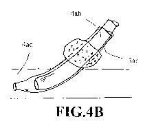
100761 FIGS. 4A-4C show schematics of placing a hemostatic cuff (4aa) on the
expandable sheath (3aa) at its retracted state that is configured for
advancing the endograft
(4ab) into a blood vessel (4ac). After the endograft is in place, the expanded
sheath (3ac) is
removed while the hemostatic cuff is positioned over the endograft at about
the opening (4ad)
of the blood vessel (4ac) temporarily.
-14-
CA 02724771 2010-11-15
WO 2009/140638 PCT/US2009/044212
100771 FIG. 5 shows steps of advancing an endograft through an iliac artery
(13a)
to the aorta. With small or stenotic iliac arteries, it may be impossible or
unsafe to advance a
large sheath. Therefore an expandable sheath at its small state (3aa) is
advanced and then
radially expanded to allow passage of large devices (5aa) as illustrated in
FIG. 5A to FIG. 5C.
100781 Some aspects of the invention provide a radially expandable sheath as a
guiding sheath, comprising a continuous integral sheath body with a thin wall
that is radially
expandable under outward forces, wherein the radially expandable sheath is
characterized
with substantially little or no axial stretchability or contraction from a
first configuration of a
compressed state to a second configuration of an expanded state and vice
versa.
100791 A method of temporarily placing a hemostatic cuff at an incision of a
blood vessel when inserting an endograft into a patient, the method
comprising: (a) loading
the hemostatic cuff on the expandable sheath of claim I at the first
configuration; (b)
inserting the compressed sheath through the incision into the blood vessel;
(c) advancing the
endograft into the blood vessel via a sheath lumen to expand the sheath to the
second
configuration; (d) holding the hemostatic cuff at proximity of the incision;
and (e) removing
the expanded sheath after the endograft and the cuff are properly positioned
in place.
The Neck Subassembly
100801 In one embodiment for a short neck endograft application, renal stent
grafts could be implanted in the renal arteries, wherein the metal mesh
portion of the renal
stent graft is removably connected to an RF electrode (6ad) that is
electrically connected to an
outside RF source. As shown in FIG. 6A, the exposed end (6ab) of the renal
stent graft (6aa)
extends or protrudes beyond the aorta inner wall (6ac). FIG. 6B shows an
endograft (6ae)
being positioned inside the aorta, whereas the exposed end of the renal stent
graft (6aa)
contacts and presses against the external surface of the endograft intimately.
By applying RF
current to the stent edge (6ab), a hole (bah) is created in endograft fabric
(shown in FIG. 6C)
for blood communication between the aorta (6ag) and the renal arteries (6af).
The endograft
is intimately and tightly pressed against the boundary of the renal artery
ostium to prevent
blood leakage or seepage.
[0081] Some aspects of the invention provide a method for placing an endograft
for treatment of AAA while preserving blood communication from aorta to renal
arteries,
-15-
CA 02724771 2010-11-15
WO 2009/140638 PCT/US2009/044212
comprising: (a) placing a renal stent inside a renal artery, wherein a first
end of the renal stent
is inside the renal artery whereas the second end protrudes beyond the renal
artery ostium; (b)
placing the endograft in the AAA area, wherein the endograft intimately
contacts the renal
artery; (c) applying RF energy to the second end of the renal stent so to
create a hole by RF
energy and to protrude the renal stent into a lumen of the endograft. In one
embodiment, the
endograft comprises a pair of D-grafts. In another embodiment, the endograft
comprises a
pair of grafts with mate-able proximal sections.
10082] FIG. 7 illustrates one method for placing a neck subassembly of an
endograft. As shown in FIG. 7A, one may use common polymer physical data to
create an
elastomeric graft cast construct (7aa) of juxta-renal aorta. The material used
may be porous,
biocompatible, durable and elastomeric. The construction could be similar to a
rapid
prototype process. In a second step shown in FIG. 7B, limbs (lab) are
compressed and cast
with gelatin. Guide tubes are inserted to accept wires (lac) for the construct
(7aa). In
operations, the construct (7aa) is compressed and loaded in a delivery sheath
(lad) as shown
in FIG. 7C. The construct is thereafter released about the renal artery
region, whereas each
limb (lab) is inserted into the renal artery (6af) via the guide wires
introduction (see FIG.
7D).
10083] FIG. 8 illustrates one method of bypassing the renal arteries when
implanting an AAA endograft. As shown in FIG. 8A, a tubular stent graft (8aa)
from brachial
artery is implanted about the aorta and renal region, wherein the distal end
is inserted into the
renal artery (6af) and the proximal end stays inside the aorta (6ag). Juxta-
renal foam cuff
(8ab) is then applied to the proximal ends of the implanted stent grafts (8aa)
under supra-
mesenteric fixation (shown in FIG. 8B). A pair of aorto-iliac grafts (8ac) as
the endograft is
then inserted through the cuff (shown in FIG. 8C), whereas the distal end of
the aorto-iliac
graft is inserted into the iliac artery. The justa-renal foam cuff is sized
and configured to
avoid migration, endoleak or blockage to normal blood flow.
10084] One aspect of the invention provides an endograft system for treatment
of
AAA, comprising a cuff and four endograft units, each endograft unit having a
proximal end
and a distal end, all four proximal ends are placed and fixed at the cuff
whereas a first distal
end extends and is fixed in right renal artery, a second distal end extends
and is fixed in left
-16-
CA 02724771 2010-11-15
WO 2009/140638 PCT/US2009/044212
renal artery, a third distal end extends and is fixed in right iliac artery
and a fourth distal end
extends and is fixed in left iliac artery. In one embodiment, the endograft
system isolates
blood from flowing into or in fluid communication with the aneurysmal zone as
means for
preventing endoleak.
10085] FIG. 9 illustrates one method for placing an endograft and a renal
stent for
treatment of AAA in a patient. In operations, an endograft (9aa) is placed in
an aorta (6ag)
over renal arteries (6af). FIG. 9A shows that a wire (9ab) is inserted to
pierce the graft at
about the renal artery region (9ac). FIG. 9B shows that a special dual lumen
stent catheter
(9ad) is used to push through the graft at the piercing point (9ac).
Thereafter, the balloon
(9ae) of the dual lumen stent catheter is inflated to create lumen for the
renal stenting
operation, wherein one end of the renal stent (6aa) is placed inside the renal
artery and the
other end is within the aorta (as shown in FIGS. 9C and 9D).
10086] FIG. 10 illustrates an alternate method for placing an endograft and a
renal
stent for treatment of AAA. In operations, a graft (1 Oaa) is placed in an
aorta (6ag) over renal
arteries (6af). FIG. IOA shows that a wire (10ab), preferably with a sharp
end, is inserted to
pierce the graft at about the renal artery region (IOac). FIG. IOB shows that
a special 2-lumen
guide catheter (10ad) is used, wherein the second lumen accepts wire to pierce
through the
graft at the piercing point (IOac). Thereafter, the balloon (I Oae) of the 2-
lumen guide catheter
is inflated to create orifice (I Oaf) for the renal artery. The curved wire is
inserted in the guide
and is pulled down to center the orifice (as shown in FIG. 10C). Subsequently,
the renal
artery is catheterized and stented (as shown in FIG. I OD), wherein one end of
the renal stent
(IOag) is placed inside the renal artery and the other end is within the
endograft (as shown in
FIG. I OE).
100871 Some aspects of the invention provide a method for placing an endograft
for treatment of AAA while preserving blood communication from aorta to renal
arteries,
comprising: (a) placing a renal stent inside a renal artery, wherein a first
end of the renal stent
is inside the renal artery whereas the second end is positioned at about the
renal artery
ostium; (b) placing the endograft in the AAA area, wherein the endograft
intimately and
compressively contacts the renal artery ostium; (c) providing a wire at about
the ostium site
and piercing through the endograft so to create a hole into the renal artery
configured for
-17-
CA 02724771 2010-11-15
WO 2009/140638 PCT/US2009/044212
blood communication from aorta to the renal artery. In one embodiment, the
method is
followed by another step of balloon expansion at about the hole to enlarge the
hole size.
100881 FIG. 11 shows an alternate endograft for treatment of AAA. The
endograft
(11 aa) comprises an impermeable section that begins from a proximal end (11
ac) of the
endograft located below the renal artery ostia (11af) and extends into the
iliac arteries, and a
porous section placed across renal arteries. The porous section may be created
by securing a
macro-porous sleeve (II ab) over the impermeable section, for example, an
overlap zone
(11 ad) extending from the proximal end (11 ac) to the distal end (I 1 ae) of
the porous sleeve.
Thus blood could flow from aorta (6ag) to renal arteries via the porous sleeve
and to iliac
arteries via the endograft while bypassing the aneurismal zone.
[0089] Some aspects of the invention relate to an endograft for treatment of
an
abdominal aortic aneurysm (AAA) comprising an impermeable section for
excluding blood
communication between a lumen of the endograft and a surrounding aneurysmal
sac, and a
porous section configured for placement across a renal artery ostium. In one
embodiment, the
endograft comprises a macro-porous sleeve that is longer than the impermeable
section, the
porous section being created by securing the macro-porous sleeve over at least
a portion of
the impermeable section.
[0090] FIGS. 12-14 show one or another alternate embodiment of a stent graft
or
endograft, system, and methods of use for treatment of abdominal aortic
aneurysms.
Specifically, FIG. 12 shows one embodiment of stent grafts (21) of the present
invention to
be percutaneously deployed into the aneurismal aorta region (10) for
implantation. In one
embodiment, the stent graft (21) comprises a neck attachment section (22), the
graft body or
trunk (23), and two leg sections (24a), (24b). The neck attachment section
(22) may comprise
a single neck attachment element (32) as shown in FIG. 13 or a double neck
attachment
element (22a) and (22b) shown in FIG. 12. In the exemplary embodiment after
delivering the
graft to the position, the neck attachment element is radially expandable that
is sized and
configured to contact intimately the tissue of the aortic wall for securing
the neck attachment
section in place with little or no device migration. The securing operation
may be
accomplished by a number of barbs protruding therefrom for anchoring. The
barbs can be
configured to deploy outwardly in sync with the expansion of the neck
attachment element.
-18-
CA 02724771 2010-11-15
WO 2009/140638 PCT/US2009/044212
The single neck attachment element (32) may be mesh-like or porous (for
example, without
cloth covering or graft material) and is generally attached to the aorta
distal to the renal
arteries (12). The first (22a) of the double neck attachment element may be
secured to the
aorta proximal to at least one renal artery (12) while the second (22b) of the
double neck
attachment element is secured to the aorta distal to the renal artery. In one
embodiment, the
expanded diameter of the first of the double neck attachment is different from
that of the
second one.
100911 For the neck attachment section with a single neck attachment element
(32) as shown in FIG. 13 or a plural neck attachment element as shown in FIG.
12, the length
of graft trunk distal to the attachment element for seal and fixation in
aortic neck is
appropriately sized and configured according to the determined diameter of
aortic neck.
Similarly, the length and diameter of each leg section for seal in the iliac
artery is also
appropriately sized and configured according to the determined native diameter
of the iliac
artery. In one preferred embodiment, the single neck attachment element (32)
and/or the
second neck attachment element (22b) of the double neck attachment elements
may have the
graft material integrally extending from the graft trunk.
100921 U.S. Pat. No. 6,383,193 issued on May 7, 2002, entire contents of which
are incorporated herein by reference, discloses a delivery system for the
percutaneous
insertion of a self-expanding vena cava filter device system, the system
comprising
constraining the filter in a compact condition within an elongated, radially
flexible and
axially stiff tubular member. The neck attachment section could be a shape
memory
wireframne that is axially rigid and radially expandable so that it can be
much more simply
and quickly inserted, deployed and there permanently fixed by associated
external ligature,
such as barbs or anchors on the wireframe. The wireframe may comprise a
substantially
zigzag pattern, mesh-like or other appropriate pattern suitable for radial
expansion and
anchoring.
100931 A wireframe made from shape memory alloy may be deformed from an
original, heat-stable configuration to a second, heat-unstable configuration.
The application
of a desired temperature causes the alloy to revert to an original heat-stable
configuration. A
particularly preferred shape memory alloy for this application is binary
nickel titanium alloy
-19-
CA 02724771 2010-11-15
WO 2009/140638 PCT/US2009/044212
(NiTi alloy) comprising about 55.8 percent Ni by weight, commercially
available under the
trade designation Nitinol. This NiTi alloy may be configured to undergo a
phase
transformation at physiological temperatures. A stent or wireframe made of
this material is
deformable when chilled. Thus, at low temperatures, for example, below twenty
degrees
centigrade, the stent is compressed so that it can be delivered to the desired
location. The
stent may be kept at low temperatures by circulating chilled saline solutions.
The stent
expands when the chilled saline is removed and when it is exposed to higher
temperatures
within the patient's body, generally around thirty-seven degrees centigrade.
100941 The graft trunk (23), configured to anchor and seal the stent graft
within a
vessel and comprising a substantially tubular stent structure, can be an
expandable tubular
metal stent with graft material inside. The graft material or component may be
made from
any number of suitable biocompatible materials, including woven, knitted,
sutured, extruded,
or cast materials comprising polyester, polytetrafluoroethylene, silicones,
urethanes, and ultra
lightweight polyethylene, such as that commercially available under the trade
designation
SpectraTM. The materials may be porous or nonporous. Exemplary materials
include a woven
polyester fabric made from DacronTM or other suitable PET-type polymers which
is folded to
reduce its size and which is attached to one or both ends of a radially
expandable stent by
means of sutures or gluing. When the stent self-expands or is balloon
expanded, the graft
unfolds around the stent. In one embodiment, there is provided a porous
endoluminal graft
which is made of a spun matrix of polyurethane combined with a self-expanding
stent. The
elastomeric polyurethane fibers allow the graft to compress with the stent and
thereby pen-nit
delivery of the stent-graft through a relatively small catheter.
100951 Graft material is affixed to at least a portion of the trunk section
(23) and
all of the legs (24a, 24b). The graft material may be attached to various
portions of the
underlying structure by sutures. In one embodiment, the graft material is
affixed with a
continuous stitch pattern on the end of the trunk section (23) and by single
stitches elsewhere.
It is important to note that any pattern may be utilized and other devices,
such as staples, may
be utilized to connect the graft material to the underlying structure. The
sutures may comprise
any suitable biocompatible material that is preferably highly durable and wear
resistant. In
one embodiment, the graft trunk intimately contact the aorta at an upper
contact region (14)
-20-
CA 02724771 2010-11-15
WO 2009/140638 PCT/US2009/044212
and the lower contact region (15) to prevent blood from seeping into the
aneurysmal region
(11) of the abdominal aorta.
100961 In the exemplary embodiment, the first (24a) of the leg section of the
stent
graft (21) is placed within the right common iliac artery (I 3a), wherein the
distal end member
(25a) of the first leg section (24a) is with a self-expandable or balloon
expandable Nitinol
wireframe. Similarly, the second leg section (24b) is inserted into the left
common iliac artery
(I 3b) with a self-expandable or balloon expandable distal end member (25b).
After the stent
graft is positioned and deployed in place, the aneurysmal region (28) of the
aorta (outside of
the core channel) may be further treated with foam embolization. The ends of
the leg section
(24a) and (24b) may be flared for better anchoring and sealing in the
downstream arteries.
The flared section may be formed by flaring the last portion of the stent
element. The leg
sections are the bypass conduits through which the blood flows in the
aneurysmal section of
the artery. By eliminating the blood flow to the diseased section, the
pressure is reduced and
thus there is less of a chance of the aneurysm rupturing.
[00971 Referring now to FIG. 13, there is illustrated an exemplary embodiment
of
an endograft or stent graft (31) with a graft trunk (33) having anchoring and
sealing
components at each end section in accordance with the present invention. In
one
embodiment, the stent graft (31) is characterized with a central trunk section
that is gradually
narrowed from either end section of the trunk (33). In another embodiment, the
middle
section of the graft trunk (33) is equipped with at least one foam-injecting
port (36). The
foam-injecting port can be a self-sealing site for accessing to a foam-
containing catheter with
a needle or a one-way valve for accessing to a foam-containing catheter with a
blunt tip. In
still another embodiment, the stent graft (31) is characterized with a polymer
coat or polymer
membrane (38) at an exterior surface of the trunk, wherein the polymer coat or
membrane can
be either thrombogenic to promote foam embolization or non-thrombogenic to
mitigate foam
adhesion to the stent graft.
100981 Some aspects of the invention relate to an endograft for treatment of
an
abdominal aortic aneurysm (AAA) comprising a neck attachment section, a graft
body, and a
leg section, the neck attachment section having a multiple-anchoring mechanism
that
comprises at least a first anchoring element for placement at proximal to a
renal artery and a
-21-
CA 02724771 2010-11-15
WO 2009/140638 PCT/US2009/044212
second anchoring element axially spaced apart from the first anchoring
element, wherein the
second anchoring element is configured for placement at distal to the renal
artery. In one
embodiment, the multiple-anchoring mechanism comprises a third anchoring
element
configured for placement at about a region between two renal arteries.
100991 One aspect of the invention relates to an endograft for treatment of
AAA
comprising a neck attachment section, a first foam tube having a proximal end
and a length to
extend from the neck attachment section to a first iliac artery for fixation
inside the first iliac
artery, and a second form tube having a proximal end and a length to extend
from the neck
attachment section to a second iliac artery for fixation inside the second
iliac artery, wherein
both foam tubes are secured to the neck attachment section. In one embodiment,
the first
proximal end of a first foam tube is located at a substantial distance
proximal to the second
proximal end of a second foam tube. In another embodiment, the neck attachment
element
comprises a hanger, and wherein the proximal end of the first foam tube is
configured with a
hook to securely couple the hook to the hanger. In still another embodiment,
the proximal end
of the first foam tube is magnetically coupled to the neck attachment element.
In a preferred
embodiment, a distal end of the first foam tube is flared to anchor and seal
the distal end to
surrounding tissue of the first iliac artery or wherein a distal end of the
first foam tube is
balloon expanded to anchor and seal the distal end to surrounding tissue of
the first iliac
artery, or wherein a distal end of the first foam tube is made of shape memory
material to
anchor and seal the distal end to surrounding tissue of the first iliac
artery.
10100] One aspect of the invention relates to an endograft, wherein a proximal
section of the foam tubes is made of inflatable elements, and wherein the
proximal section is
distendable to anchor and secure the proximal section against wall of a blood
vessel. In one
embodiment, at least one of the foam tubes further comprises an inflatable
tube body. In
another embodiment, at least one of the foam tubes comprises a double-walled,
baffled tube
body filled with form-filling material that functions as a flexible graft with
sufficient hoop
strength to obviate use of a radial positioning structure. In still another
embodiment, a portion
of the baffled layer of at least one end of the foam tube is everted to create
a cuff. In a
preferred embodiment, an aneurysm sac of the AAA is filled with foam material
that is
subsequently hardened in situ, wherein the foam material is introduced via a
one-way valve
-22-
CA 02724771 2010-11-15
WO 2009/140638 PCT/US2009/044212
mounted on the first form tube into the aneurysm sac, and wherein the foam
material is
selected from the group consisting of polyvinyl alcohol foam, poly(ethylene-co-
vinyl
alcohol), cellulose acetate, poly(2-hydroxyethyl methacrylate), acrylates, and
combinations
thereof. The foam material is treated with UV light or heat in situ.
The Cuff Subassembly
10101] Referring now to FIG. 14, there is illustrated an exemplary embodiment
of
a modular biluminal endograft system with components and procedures for
placing such a
system in a body in accordance with the present invention. Some aspects of the
invention
relate to a method of repairing an abdominal aortic aneurysm in the arterial
wall at about the
aorta and the right and left iliac arteries comprising the steps of. (a)
percutaneously
introducing and advancing a guidewire into one of the right and left femoral
arteries, into the
respective one of the right and left iliac arteries and then into the lumen of
the aorta beyond
the area of the aneurysm; (b) assembling a neck attachment element in a
collapsed state about
a distal end segment of a first deployment catheter, wherein the first
deployment catheter
having a guidewire lumen formed therein adapted to be fitted over the
guidewire; (c)
delivering the neck attachment element to a site of the aorta close to the
renal artery ostium to
provide an attachment seat of predetermined size approximating the diameter of
the aorta
lumen beyond the area of the aneurysm; (d) deploying by means of self-
expanding or
balloon-expanding the neck attachment element to anchor or secure the element
in place
with, say barbs; (e) withdrawing the first deployment catheter; (f) assembling
a first
elongated tubular graft prosthesis about a distal end segment of a second
deployment
catheter, the first graft prosthesis having a continuous side wall extending
between the distal
end to the proximal end, wherein the graft prosthesis may be reinforced with
metal mesh or
stenting element at either end or both ends; (g) delivering the first graft
prosthesis so the
proximal end is positioned about the neck attachment element and the distal
end about one of
the right iliac artery; (h) deploying by means of anchoring the proximal end
of the first graft
prosthesis onto the neck attachment element while deploying the metal mesh in
the right iliac
artery; (i) percutaneously withdrawing the second deployment catheter; (j)
repeating steps f to
step i with a second elongated tubular prosthesis and the third deployment
catheter and
having a deployed metal mesh in the left iliac artery. In a preferred
embodiment, the
-23-
CA 02724771 2010-11-15
WO 2009/140638 PCT/US2009/044212
circumferential area next to the luminal openings of the proximal end of the
two graft
prostheses are sealed to prevent any blood from flowing into the exterior of
the two
prostheses in the abdominal aneurysm. In another preferred embodiment, the
distal end is
sized and configured, after deployment, to seal the graft lumen and iliac
arteries from the
aneurysm section.
101021 As shown in FIG. 14A, the goal for treating an abdominal aortic
aneurysm
is to limit the blood flow in the abdominal aorta substantially constant by
maintaining the
blood flowing along about the dashed line (12). A second goal is to supply
adequate blood
volume to the iliac arteries (13a, 13b) from the thoracic artery by bypassing
the aneurismal
artery portion (11). In the exemplary embodiment as shown in FIG. 14B, the
first step of
procedures for positioning an endograft system is to percutaneously delivery a
neck
attachment element (41) to the healthy tissue above the aneurysm, but distal
to the renal
arteries (12). Thereafter, the neck attachment element is deployed in place
with anchoring
members, such as barbs (42).
10103] In one embodiment, balloon expansion of the neck attachment element
occurs at a pressure sufficient to cause the stent-like element to radially
expand and to anchor
the element to the surrounding tissue.
101041 The second step is to percutaneously deliver a first tube (43) with
adequate
strength, flexibility and length as shown in FIG. 14C so the proximal end (44)
of the tube
(43) is secured to part of the neck attachment element (41) while the distal
end section (45) is
placed within the right iliac artery (13a). In one embodiment, the neck
attachment element is
equipped with a hanger (62) and the proximal end (44) of the first tube is
configured with a
hook (61) to securely couple the hook to the hanger. Other mechanisms of
coupling, such as
magnetic coupling or button-slot coupling may also be feasible. The distal end
(46) of the
first tube may be flared as discussed above, balloon expanded, or made of
shape memory
material to anchor and seal the distal end to the surrounding tissue.
101051 Referring now to FIG. 14D, a second tube (53) with adequate strength,
flexibility and length is percutaneously delivered to the abdominal aorta area
so the proximal
end (54) of the tube (53) is secured to part of the neck attachment element
(41) while the
distal end section (55) is placed within the left iliac artery (13b). As
discussed above, the
-24-
CA 02724771 2010-11-15
WO 2009/140638 PCT/US2009/044212
distal end (56) of the second tube may be flared, balloon expanded, or made of
shape memory
material to anchor and seal the distal end to the surrounding tissue.
101061 Before foam embolization is initiated, the aneurysmal aorta region (11)
may be sealed from the rest of the blood flowing vessel. In one embodiment as
shown in FIG.
14E, a first proximal sealing member (47) is provided to the first tube (43)
and a second
proximal sealing element (57) is provided to the second tube (53). The sealing
elements (47,
57) are sized, configured and placed overlap to each other so to cover the
open area beyond
the tubes at about the upper healthy aorta region. The sealing members (47,
57) can be
provided as an integral part of the tubes. In one preferred embodiment as
shown in FIG. 15,
the proximal ends (44a, 54a) of the tubes (43a, 53a) are configured to a
trumpet shape (59)
and sized to intimately occupy the space at about the neck fixation region
(63) as shown in
FIG. 15. In one embodiment, the trumpet shaped proximal end is expandable by
using shape
memory material.
101071 In an alternate embodiment, the distal section is sealed against the
vessel
wall with a stopper (48, 58) for the first and second tubes (43, 53),
respectively. Foam
material can be introduced into the aneurysm (11) and hardened in situ (FIG.
14F). In this
case, the foam material would stay in the aneurysm even without the proximal
sealing
members (47 and 57). In the exemplary embodiment, the foam material before
hardened may
be delivered through the tubes (43, 53) into the delivering ports (49 and 59).
As discussed
above, the delivering port can be a self-sealing site or have a one-way valve
that is accessible
to foam-containing catheters.
101081 Some aspects of the invention relate to an endograft system with a neck
anchoring mechanism and two foam tubes, wherein the blood bypasses the
aneurysm via
flowing through the foam tubes from upper aorta to iliac arteries. In one
embodiment, the
aneurysm is filled with foam material that is subsequently hardened in situ.
In another
embodiment, the foam material is introduced via a one-way valve mounted on the
form tube
into the aneurysm and is hardened thereafter in situ. The foam material may be
polyvinyl
alcohol foam, EVAL poly(ethylene-co-vinyl alcohol)), cellulose acetate, p-HEMA
(poly(2-
hydroxyethyl methacrylate)), acrylates, combinations thereof. and the like.
-25-
CA 02724771 2010-11-15
WO 2009/140638 PCT/US2009/044212
10109] Polyvinyl alcohol foam (PAF) offers a number of advantages over other
embolic material, including biocompatibility, promotion of progressive
thrombosis and
fibrosis, permanence, compressibility, and manageability. The clinical cases
illustrate the
kinds of lesions that are amenable to embolization, including arteriovenous
malformations,
arteriovenous fistulas, meningiomas, nasopharyngeal tumors, and particularly
for AAA
treatment.
101101 A vascular implant formed of a compressible foam material has a
compressed configuration from which it is expansible into a configuration
substantially
conforming to the shape and size of a vascular site to be embodied.
Preferably, the implant is
formed of a hydrophobic, macro porous foam material, having an initial
configuration of a
scaled-down model of the vascular site, from which it is compressible into the
compressed
configuration. The implant could be made by scanning the vascular site to
create a digitized
scan data set; using the scan data set to create a three-dimensional digitized
virtual model of
the vascular site; using the virtual model to create a scaled-down physical
mold of the
vascular site; and using the mold to create a vascular implant in the form of
a scaled-down
model of the vascular site. To embolism a vascular site, the implant is
compressed and passed
through a delivery catheter, the distal end of which has been passed into a
vascular site. Upon
entering the vascular site, the implant expands in situ substantially to fill
the vascular site. A
retention element is contained within the catheter and has a distal end
detachably connected
to the implant. A flexible, tubular deployment element is used to pass the
implant and the
retention element through the catheter, and then to separate the implant from
the retention
element when the implant has been passed out of the catheter and into the
vascular site. In
one preferred embodiment, the compressible foam material is injected as a
transportable
moving material that is solidified in-situ and substantially conforms to the
shape and size of a
vascular site to be embodied.
Endo-plug
101111 PVA sponge with different porosities (for example, 700, 300, 30 microns
etc.) could be made as tubes in different sizes, for example, a 25 mm "double
D"
configuration with 7mm lumen or a I0mm long tube with 7mm lumen. A PVA sponge
in a
dried state is easily compressed and could fully re-hydrate and expand to its
original state in
-26-
CA 02724771 2010-11-15
WO 2009/140638 PCT/US2009/044212
minutes. One aspect of the invention is to introduce PVA sponge tube with
optimal porosity
in a compressed dry form as an endo-plug and allow it to expand in-situ across
aneurysm.
Through lumen of the tube would then be stented or stent-grafted at a diameter
less than that
of the expanded sponge. The porous sponge plug could be compressed by applying
vacuum,
by wrapping or injected in a funnel. The dried sponge plug could be crimped on
a stent or
balloon, pushed through sheath over a wire, or premounted on its own delivery
apparatus.
101121 The delivery sheath method comprises a first step of inserting a long
sheath with a tip marker up to the insertion site in a patient. Load the
compressed plug on a
pusher/cannula and then insert the plug/cannula through sheath up to a desired
deployment
site. After deployment, withdraw sheath until cannula marker and sheath tip
marker line up.
This will anchor the distal about one cm of sponge in sheath while majority of
the sponge is
hydrated. Thereafter, complete deployment by withdrawing sheath over the
distal one cm to
release the sponge in place.
101131 FIG. 16A shows "double D" sponges and FIG. 16B shows "ribbed
sponges" to provide interlocked seal in blood vessels. The conformable pair of
sponges
allows insertion of bifurcated grafts in 2 parts from each groin, resulting in
lower profiles. In
one embodiment, the delivery cannula has multiple hydration holes to speed
expansion of
sponge. In another embodiment, pulse delivery of warm saline speeds sponge
expansion too.
101141 One aspect of the invention provides a conformable pair of spongy endo-
plugs for treatment of aneurysmal vessels, wherein the plugs are compressed in
a first
configuration for delivery to the vessels and expanded via re-hydration to a
second
configuration to plug the vessels. In one embodiment, the plug has a through
lumen. In
another embodiment, each plug has matching flat surface facing each other. In
still another
embodiment, each plug has a matching ribbed surface to provide interlocked
seal in vessels.
In an alternate embodiment, the expansion of the endo-plug is enhanced with a
shape
memory Nitinol wire.
101151 The sponge plug (17aa) can be reinforced or supported with anchor
structures as shown in FIG. 17A. The sponge plug has an embedded wire struts
(17ab), hooks
(17ac) and a through lumen (17ad). The sponge plus can also incorporate
radiopaque
-27-
CA 02724771 2010-11-15
WO 2009/140638 PCT/US2009/044212
elements as markers (17ae) or tantalum powder (17af) for x-ray visualization
(FIG. 17B and
FIG. 17C).
101161 FIG. 18 shows various configurations of sponge endo-plugs, including
the
suture-supported sponge plug that can change the shape by tightening the
suture and the wire-
supported sponge plug that can change the shape when the wire is made of shape-
memory
Nitinol material or the like.
101171 One aspect of the invention provides a spongy endo-plug for treatment
of
aneurysmal vessels, comprising an anchoring means for securing the plug in
place without
undue migration. In another embodiment, the endo-plug is configured radiopaque
or
incorporated with at least one radiopaque market.
The Endoleak
101181 Exclusion of the aneurysm sac is the main goal of the stent-graft
treatment,
and clinical success is defined by the "total exclusion" of the aneurysm.
However, at times,
failure of the stent-graft to totally exclude blood flow to the aneurysm sac
may occur. As a
matter of fact, endoleak is the major cause of complications, and thus failure
in endoluminal
treatment of AAA. Endoleak is a term that describes the presence of persistent
flow of blood
into the aneurysm sac after device placement. The management of some types of
endoleak
remains controversial, although most can be successfully occluded with
surgery, further stent
implantation, or embolization. Four types of endoleaks have been defined,
based upon their
proposed etiology.
101191 A type I endoleak, which occurs in 0 to 10 percent of endovascular
aortic
aneurysm repairs, is due to an incompetent seal at either the proximal or
distal attachment
site. Etiologies include undersizing of the diameter of the endograft at the
attachment site and
ineffective attachment to a vessel wall that is heavily calcified or
surrounded by thick
thrombus. Although such a leak can occur immediately after placement, a
delayed type I
endoleak may be seen on follow-up studies if the device is deployed into a
diseased segment
of aorta that dilates over time, leading to a breach in the seal at the
attachment site.
101201 Type I endoleaks must be repaired as soon as they are discovered
because
the aneurysm sac remains exposed to systemic pressure, predisposing to
aneurysmal rupture,
and spontaneous closure of the leak is rare. If discovered at the time of
initial placement,
-28-
CA 02724771 2010-11-15
WO 2009/140638 PCT/US2009/044212
repair may consist of reversal of anticoagulation and reinflation of the
deployment balloon for
an extended period of time. These leaks may also be repaired with small
extension grafts that
are placed over the affected end. These methods are usually sufficient to
exclude the
aneurysm. Conversion to an open surgical repair may be needed in the rare
situation in which
the leak is refractory to percutaneous treatment.
[0121] Type 11 endoleaks are the most prevalent type, occurring in 10 to 25
percent of endovascular aortic aneurysm repairs, and describe flow into and
out of the
aneurysm sac from patent branch vessels. They are most often identified on the
postprocedural CT, appearing as collections of contrast outside of the
endograft, but within
the aneurysm sac. The most frequent sources of type 11 endoleaks are
collateral back flow
through patent lumbar arteries and a patent inferior mesenteric artery.
Because the sac fills
through a collateral network, the endoleak may not be visualized on the
arterial phase of CT
scanning; thus, delayed imaging is required.
[0122] The significance and management of type 11 endoleaks is controversial.
Some investigators argue that, since spontaneous resolution occurs in 30 to
100 percent of
cases, a "wait and see" approach is preferable, while carefully following
aneurysm volume
and morphology on CT imaging. However, systemic pressures have been noted
within the
aneurysm sac in the presence of type II endoleaks, indicating a more tenuous
situation.
[0123] Type III and type IV endoleaks are much less common. Type III endoleaks
represent flow into the aneurysm sac from separation between components of a
modular
system, or tears in the endograft fabric. Type IV endoleaks are due to egress
of blood through
the pores in the fabric. Type IV leaks heal spontaneously, while type III
leaks are repaired
with an additional endograft to eliminate systemic flow and pressure in the
aneurysm.
[0124] Flow identified within the aneurysm sac (endoleaks) can represent a
failure
of the attachment sites (type I) or device (type 111). There is general
agreement that these
failure modes necessitate urgent repair because blood flow and systemic
pressure will
continue to be transmitted into the aneurysm sac, putting the patient at
continued risk for
aneurysm enlargement and rupture.
[0125] One aspect of the invention relates to devices and methods for endoleak
solutions by extruding or inserting soft, thrombogenic 'pipe-cleaner' like
soft filler material
-29-
CA 02724771 2010-11-15
WO 2009/140638 PCT/US2009/044212
(I9aa) into AAA sac, preferably through a delivery catheter (shown in FIG.
19). The material
could be PVA (polyvinyl alcohol), Dacron (polyester) thread and the like with
enhanced
thrornbogenic properties. The diameter of the `pipe-cleaner' like material
could be from
thread-like (0, 0-0) up to 10-20 mm. Since the material is soft and cannot be
pushed, one
solution is to pull the `pipe-cleaner' like material through a catheter (19ab)
by a tip
mechanism (as shown in FIG. 20). In one embodiment, the tip (20aa) is
configured to move
helically forward when turned in one direction so to pull the material
outwardly. The turning
of the tip can be either via a connected mandrill or wire that transmits the
torque to a
proximal handle of the catheter (19ab), or via saline injection to push and
turn the tip section.
After the material is placed inside the sac and separated from the tip, the
tip is withdrawn into
the catheter lumen when the tip is turned in an opposite direction. And the
catheter is
withdrawn from the patient.
10126] In another embodiment, the soft filler material as shown in FIG. 19 may
be
pulled out of a catheter by a repositionable snare that may movably be located
in a second
lumen (21 ac) of a dual-lumen catheter. FIG. 21 A shows a snare (21 aa)
engaged with the soft
filler material at point AA in a first lumen (21 ab) of a dual-lumen catheter,
whereas FIG. 21 B
shows the soft filler material (19aa) is pulled upward by the snare. The snare
is thereafter
loosened from the soft filler material at point AA and repositioned at point
BB and engaged
with the soft filler material again (shown in FIG. 21C) so to repeat the
engagement-pulling-
disengagement-reposition operation until the soft filler material (19aa) is
inserted into the sac
as desired.
10127] In an alternate embodiment, a catheter set with a concentric inner
catheter
(22ab) and an outer catheter (22aa) is used to deliver the soft filler
material (19aa) into the
sac, wherein a balloon (22ac) is movably located inside the gap between the
lumen of the
outer catheter and the sheath of the inner catheter. In one embodiment, the
balloon is sized
and configured to show a circumferential concave surface. The soft filler
material occupies
the lumen of the inner catheter tightly and/or intimately before the insertion
step. The catheter
set is then delivered to the sac region. In operations, the inner catheter is
first pushed
outwardly to deliver part of the soft filler material inside the sac as shown
in FIG. 22A. The
distal end of the inner catheter is pushed outwardly and engages the balloon
at about the
-30-
CA 02724771 2010-11-15
WO 2009/140638 PCT/US2009/044212
proximal edge of the balloon. Then the balloon (22ac) is inflated to pin the
soft filler material
against the sheath of the outer catheter so the inner catheter can be
retracted inwardly. The
operation can be repeated until all soft filler material is delivered inside
the sac.
10128] In still another embodiment, a nozzle catheter with a narrowed distal
section can be used to hydraulically deliver the soft filler material into the
sac. FIG. 23 shows
a nozzle catheter (23aa) of the present invention, comprising a catheter lumen
(23ab), a
necked-down lumen (23ac), wherein the soft filler material occupies a portion
of the catheter
lumen in a loose manner. Saline or appropriate fluid (23ad) is hydraulically
introduced at a
speed substantially to squeeze the soft filler material through the necked-
down section so to
push or carry the soft material into the sac.
10129] Some aspects of the invention relate to a method of inserting soft,
thrombogenic `pipe-cleaner' like soft filler material (I 9aa) into AAA sac,
preferably through
a delivery catheter. The material could be made of PVA (polyvinyl alcohol),
Dacron
(polyester) thread and the like with enhanced thrombogenic properties.
AAA Device and Methods
101301 Some aspects of the invention relate to an improved modular AAA device
that meets clinical needs of a percutaneous delivery (preferably with a 12
French or smaller
delivery catheter) in a cath-lab with local anesthesia. The modular device may
have multiple
sizes, but not custom-made. The device is configured fully adaptable
anatomically with
respect to neck attachment, tortuosity and iliac anatomy, among others. The
current device is
particularly suitable for implantation in a patient with a short neck and/or
two renal arteries
not at the same axial elevation along the aorta. FIG. 7 shows some procedures
and means for
solving the problems of two renal arteries not at the same axial elevation
along the aorta.
FIG. 9 shows some procedures and means for solving the problems of a short
neck.
101311 FIG. 24 shows comparison of: (A) a conventional AAA device, and (B) an
improved AAA device of the present invention. The prior art device is usually
a tubular graft
with a bifurcated distal section for inserting into iliac arteries. The
limitations of conventional
devices may include, among others, large introducer size, metal/fabric
construction, prone to
endoleak, need for exact size, and need for large device inventory. The new
improved device
of the present invention may comprise: compressible foam tube, percutaneous
delivery, 2-10
-31-
CA 02724771 2010-11-15
WO 2009/140638 PCT/US2009/044212
mm lumens, introduced soft material, cured in-situ with UV, heat or chemical
reaction, and
lattice of foam filling blood vessels.
10132] As foam cures, it becomes harder which relieves pulsatile wall stress
on
aneurysm (25ac) in-situ. In initial soft configuration, foam (25ab) fills
lumen to seal (as
shown in FIG. 25A). The foam tube was introduced in compressed configuration
(as shown
in FIG. 25B) over a balloon (25ad) or other expandable means (stents, basket,
etc.) from a
delivery apparatus (25ae) for expanding the compressed foam tube (25aa). The
foam tube
expands with fluid contact and/or balloon expansion (as shown in FIG. 25C).
The foam
lattice becomes hardened by curing with UV, heat, chemical or biological via
balloon
delivery. The curing time could be from about 1 minute to weeks depending on
material
selection to meet clinical needs.
10133] In one embodiment, the tubular graft (26aa) comprises cuffs (26ab) at
each
end, wherein the cuff has prongs (26ac) that hold the graft in place while the
cuffs heal (as
shown in FIG. 26A). FIG. 26B shows a top cross-sectional view of the tubular
graft (26aa). In
another embodiment, the cuff of the endograft system of the present invention
comprises a
foam cuff, wherein the foam may be made from hardenable foam material and
hardened in
situ. In still another embodiment, the first proximal end of a first endograft
is at a substantial
distance proximal to the second proximal end of a second endograft.
(0134] In another embodiment, a device for creation of a low-profile,
percutaneous delivery, endoleak resistant vascular graft is shown in FIG. 27A.
The principal
concept for such a device (27aa) is an inflatable prosthesis, preferably with
inflatable ends
(27ab) and/or an inflation body (27ac), with a through lumen. The prosthesis
solves the two
major drawbacks of prior art scent-grafts of a large introduction size and
difficult vessel
sizing resulting in endoleaks. The prosthesis could be introduced in a
compressed fonn and
inflated with a fluid (for example, contrast and/or saline) to position and
test for leaks. When
properly positioned the cuffs would be deflated and reinflated with a liquid
polymer which
would set and harden. The hardenable liquid polymer may include EVAL
(poly(ethylene-co-
vinyl alcohol)), cellulose acetate, p-HEMA (poly(2-hydroxyethyl
methacrylate)), acrylates,
combinations thereof, and the like). The prosthesis would be made of an
ultrathin
microporous material such as PTFE, polyester and the like. Each layer would be
very thin
-32-
CA 02724771 2010-11-15
WO 2009/140638 PCT/US2009/044212
(for example, less than 50 m ) to reduce the compressed profile. p-HEMA is a
polymer that
fonns a hydrogel in water. p-HEMA functions as a hydrogel by rotating around
its central
carbon. In air, the non-polar methyl side turns outward, making the material
brittle and easy
to grind into the correct lens shape. In water, the polar hydroxyethyl side
turns outward and
the material becomes flexible.
10135] The cuffs (27ab) could be sized and configured to be minimally larger
than
a graft for use in smaller vessels (as shown in FIG. 27B) or significantly
larger in vessels
such as in the aorta (as shown in FIG. 27C). For example, the lumen diameter,
DI, could be
between about 2 and 10 mm whereas the cuff outer diameter, D2, could be
between about 4
and 12 mm. Preferably in another application, the lumen diameter, D3, could be
between
about 6 and 14 mm whereas the cuff outer diameter, D4, could be between about
24 to 36
mm.
101361 The cuffs could be introduced separately or they could be an integral
part
pf endograft. FIG. 27D shows that the cuffs and/or graft could be temporarily
fixed in place
during the inflation and positioning phase by placement over an angioplasty
balloon (25ad).
10137] In another embodiment, a double-walled, baffled tube filled with a
hardening or form-filling material would function as a flexible graft with
sufficient hoop
strength to obviate the use of another support structure such as a metallic
stent. The baffles
(28ab) of the tube graft (28aa) are filled with liquid, self-hardening polymer
(as shown in
FIG. 28A). In one embodiment, the baffles only extend from an edge of the tube
graft
inwardly for a proper short distance (toward the opposite end) configured to
provide adequate
hoop retention strength. One method of baffle tube construction could be
extrusion of PTFE
in a 2 layer, single or multi-lumen configuration with supporting baffles as
shown in FIGS.
28B and 28C. Both inner layer (28ac) and outer layer (28ad) have a wall
thickness of about
to 30 microns. After extrusion the ends are sealed to create what is
essentially a balloon
with a through lumen (as shown in FIG. 28D). It is also useful to have 2-lumen
extrusion
with baffles (as shown in FIG. 28E). In an alternate embodiment, a portion of
the baffled
layer of at least one end of a tube could be everted to create a cuff (as
shown in FIG. 28F).
101381 In a separate embodiment, the cuffs can be constructed with multiple
through lumens so that bifurcated channels can be formed (see FIG. 29). In
this fashion, the
-33-
CA 02724771 2010-11-15
WO 2009/140638 PCT/US2009/044212
aorta can be occluded using a low profile. `'2-hole" cuff and two small
diameter grafts. For
example, two 10mm stent grafts can be inserted percutaneously, whereas a
single 24 mm
graft cannot (prior art).
Introduction Methods for In-situ Foam Grafts
101391 After a first cuff is introduced into and occupy the aortic region
below the
renal arteries (as shown in FIG. 30A), introduce a balloon catheter into the
first cuff and
inflate the balloon (step 1). Using a microcatheter or other appropriate means
in cuff lumen to
inflate cuff with fluid (step 2). Then. catheterize a second lumen at the
first cuff region (step
3). Using angiogram to check position and seal; reposition if necessary (step
4). FIG. 30B
shows steps of inserting a second cuff in iliac artery in a reduced diameter
manner (step 5).
Fill cuffs with liquid polymer and cure the liquid polymer using heat, UV,
solvent
dissolution, chemical reaction or precipitation (step 6). Then insert stent-
grafts as shown in
FIG. 30C (step 7). In an alternate embodiment, a 2-cuff graft with confonnable
or D-shaped
cuffs (as shown in FIG. 30D) could be applied.
Balloon Endograft
101401 FIG. 31 shows one embodiment of an endograft made of double layer
inflatable balloon without metal or rigid supporting component ("balloon
endograft"). The
balloon endograft (31 aa) is made of double layers with a space between the
double layers,
wherein the space is inflatable with fluid, saline or hardenable soft polymer.
In one
embodiment, the endograft (31 aa) comprises a neck attachment member (31 ab),
a tubular
main body (31 ac) and bifurcated distal ends (31 ad, 31 ae), wherein the neck
attachment
member may comprise an upper neck attachment ring unit (31ba), a lower neck
attachment
ring unit (3lbb) and at least two connecting units (31bc) that connect the
upper and lower
neck attachment ring units with throughput lumen for fluid communication. In
one preferred
embodiment, the upper neck attachment ring unit (31ba) is configured to be
placed between
the proximal renal artery (31 ca) and the distal renal artery (31 cb) whereas
the lower neck
attachment ring unit (3 l bb) is configured to be placed distal to the distal
renal artery (31 cb).
In another preferred embodiment, the number of connecting units (31bc) is
three or more so
to maintain the two neck attachment ring units substantially parallel to each
other. In one
-34-
CA 02724771 2010-11-15
WO 2009/140638 PCT/US2009/044212
embodiment, there provides an optional introduction port at one or both distal
ends, wherein
the introduction port is self-sealing or with a one-way valve for infusing
fluid into the space
to inflate the inflatable endograft.
[0141] In one exemplary embodiment, the balloon endograft is collapsed for
delivery via a delivery sheath or catheter to the AAA site with a minimum
profile. Once the
neck attachment member is placed at about the renal artery ostia and the two
bifurcated distal
ends are placed in the right and left iliac arteries respectively, fluid or
hardenable polymer
foam is introduced through the first introduction port (31 at) via an infusing
catheter (31 ag).
The hardenable polymer foam is infused until the space is totally filled with
the foam,
followed by curing or hardening in situ. In one preferred embodiment, the
upper and lower
neck attachment ring units are securely anchored to the aorta walls once the
neck attachment
member is inflated.
[0142] In an alternate embodiment, the balloon endograft is configured to have
corrugated configuration (31 ah). The corrugation with internal space is in
fluid
communication with the second introduction port (31 ai). The hardenable
polymer foam may
be introduced through the second introduction port (31 ai) via an infusing
catheter (31 aj) to
fill the corrugation space (31 ah). The corrugation of the balloon endograft
is sized and
configured to support and reinforce the endograft against endoleak. Some
aspects of the
invention relate to a balloon endograft (without any metallic or rigid
supporting members
before deployment) comprising: a neck attachment mnember, a body and two
bifurcated distal
ends, wherein the endograft is with double layers and a space between the
layers, the space is
configured to be filled with fluid or hardenable foam to inflate the balloon
endograft. In one
embodiment, the body is configured in a corrugated configuration. In another
embodiment,
the body serves to direct blood flow bypassing the aneurysm.
[0143] FIG. 32 shows one embodiment of an endograft made of two double layer
inflatable balloon bodies without metal or rigid/stiff supporting component
("balloon
endograft"). The balloon endograft having two individual graft bodies (32aa,
32ab) is made
of double layers with a space between the double layers, wherein the space is
filled with
inflatable fluid, saline or hardenable soft polymer. In one embodiment, the
endograft
comprises a neck attachment member (32ba), two tubular main bodies (32aa,
32ab) with their
-35-
CA 02724771 2010-11-15
WO 2009/140638 PCT/US2009/044212
respective distal ends (32ad, 32ae), wherein the neck attachment member may
comprise an
upper neck attachment ring (32bb), a middle neck attachment ring (32bc), and a
lower neck
attachment ring (32bd) and at least two connecting units (32be) that connect
the upper to
middle rings or middle to lower neck attachment rings with throughput lumen
for fluid
communication. In one preferred embodiment, the upper neck attachment ring
(32bb) is
configured to be inflated and securely positioned proximal to the upper renal
artery (31 ca).
The middle neck attachment ring (32bc) is configured to be placed between the
proximal
renal artery (31 ca) and the distal renal artery (31 cb) whereas the lower
neck attachment ring
unit (32bd) is configured to be placed distal to the distal renal artery
(31cb). In another
preferred embodiment, the number of connecting units (32be) is three or more
so to maintain
the neck attachment rings substantially spaced apart and parallel to each
other. In one
embodiment, there provides an optional introduction port at one or both distal
ends, wherein
the introduction port is self-sealing or with a one-way valve for infusing
fluid into the space
to inflate the inflatable endograft.
10144] Some aspects of the invention relate to a balloon endograft comprising:
a
neck attachment member, a body and at least one distal end, wherein the
endograft comprises
double layers and a space between the layers, the space being configured to be
filled with
inflatable fluid or hardenable foam to inflate the balloon endograft. In one
embodiment, the
endograft is characterized with no stiff or rigid supporting component prior
to inflating the
balloon endograft. In another embodiment, the body comprises two inflatable
tubes, each
inflatable tube having a proximal end secured to the neck attachment member, a
distal end,
and double layers with a space between the layers. In still another
embodiment, the graft body
is configured in a corrugated configuration to enhance hoop strength and
prevent the graft
body from collapsing. In a preferred embodiment, the neck attachment member
comprises
two inflatable neck attachment rings and at least two connecting units that
connect the two
rings, wherein the neck attachment rings are inflatable to anchor securely at
wall of a blood
vessel.
10145] From the foregoing, it should now be appreciated that a device system
for
treating abdominal aortic aneurysms has been disclosed. While the invention
has been
described with reference to a specific embodiment, the description is
illustrative of the
-36-
CA 02724771 2010-11-15
WO 2009/140638 PCT/US2009/044212
invention and is not to be construed as limiting the invention. Various
modifications and
applications may occur to those skilled in the art without departing from the
true spirit and
scope of the invention as described by the appended claims.
37