Note: Descriptions are shown in the official language in which they were submitted.
CA 02724997 2010-11-19
DESCRIPTION
= A NEW SELF-LOCKING SELF-DESTROYING SAFETY SYRINGE
FIELD OF THE INVENTION
The present invention relates to a medical apparatus, and particularly to a
disposable self-destroying syringe.
BACKGROUND OF THE INVENTION
A syringe is an indispensable apparatus to medical treatment. All current
syringes
are designed as being disposal so as to prevent cross infection. However, such
disposal
syringes can be reused if they are not destroyed artificially. In order to
prevent the
current disposal syringes from being reused, which may result in cross
infection and
disease spread, many types of syringes have been invented. For example, in a
syringe
where the needle retracts into the barrel when the push rod is drawn back, the
needle
may come out again when a force is applied, which may still result in cross
infection.
In another needle-retractable safety syringe disclosed in the patent No.
200410017938.0, the needle will retract into the barrel when the push rod is
drawn
back, with the needle tip tilting aside and difficult to be drawn out.
However, it is easy
for the sharp needle tip to pierce through the barrel wall, which is soft and
generally
made of common polypropylene (PP). Therefore, this syringe may still result in
cross
infection. The following three methods may be adopted for the sake of safety:
1.
Increasing the thickness of the barrel wall; 2. adding a stiffening agent into
the
polypropylene raw material; and 3. choosing a barrel with low rigidity.
However, the
cost will thus be increased, and the sharpness of the needle tip lowered,
which may
bring much suffering to the patients. The push rod can also be provided with a
defective portion. The syringe can be destroyed after injection by breakage of
the push
rod. However, such a syringe can still be reused so long as the broken push
rod is
replaced with a new one. Therefore, the complete safety cannot be guaranteed.
CONTENTS OF THE INVENTION
CA 02724997 2010-11-19
A purpose of the present invention is to provide a self-destroying syringe,
whose
push rod can be locked after injection so that it cannot be reused or
replaced.
In order to achieve the above purpose, a technical solution of the present
invention is as below:
A new self-locking self-destroying safety syringe is provided, comprising a
hollow barrel, a push rod sliding within the barrel, a rubber plug in front of
the push
rod, and a needle seat in front of the barrel. It has the following features:
The push rod
is provided with a round platform, which is provided with an elastic ratchet
that
slantingly extends toward the inner wall of the barrel; the barrel is provided
at the end
with an increasing-diameter portion; at the transient position between the
normal-diameter portion and the increasing-diameter portion of the barrel is
located a
slanting step, below which is a groove where the elastic ratchet can be
catched when
the push rod is drawn backward; and the increasing-diameter portion is
provided
inside with a circlip that can press against the bottom of the round platform.
The circlip, dynamically fitted with the inner wall of the increasing-diameter
portion at the end of the barrel, can move forward and backward axially
without
moving out of the barrel, with the moving distance longer than the distance
from the
tip of the elastic ratchet on the push rod to the bottom of the round
platform; the
internal diameter of the upper end of the circlip is slightly smaller than
that of the
barrel at the slanting step; the circlip is provided at the inner circle with
a slope; when
the push rod is installed, the elastic ratchet can move forward and furl
inward along
the slope, and the round platform can stretch the inner bore of the circlip
larger and
get into it.
The increasing-diameter portion at the end of the barrel is provided on the
inner
wall with a circle of big groove that is dynamically fitted with the circlip;
the big
groove can butt at its upper end against the top end of the circlip, and is
provided at
the lower end with a flanged step; the circlip is provided at the upper outer
circle with
a flange; and the flanged step butts against the bottom end plane of the outer
circle
flange.
= The external diameter of the round platform on the push rod is smaller than
or
2
CA 02724997 2010-11-19
equal to the minimal internal diameter of the barrel at the slanting step, but
bigger
than the minimal internal diameter of the circlip.
= There are at least two elastic ratchets that are symmetrically
positioned; the
5 distance between the symmetrical ratchet tips is smaller than the
internal diameter of
the normal-diameter portion of the barrel, but bigger than the minimal
internal
diameter of the barrel at the slanting step.
The tip of the elastic ratchet extends slantingly up to the front end of the
barrel.
There are four elastic ratchets that are symmetrically positioned.
The groove is a circle of clamping groove, whose upper end plane is a slope or
a
plane that extends outward along the direction of the tip of the elastic
ratchet; and the
15 diameter of the groove at the side wall is bigger than the distance
between the two
symmetrically-positioned ratchet tips.
For a syringe with the above-mentioned structure, the push rod can be locked
after injection in the following way: The barrel is provided at the end with
the
20 increasing-diameter portion; the self-locking mechanism can be located
at the rear end
of the barrel; the push rod is provided with the elastic ratchet that extends
to the inner
wall of the barrel; the elastic ratchet gets stuck into the groove when the
push rod is
drawn backward; the slanting step above the elastic ratchet prevents the push
rod from
moving forward, while the circlip below the elastic ratchet presses against
the bottom
25 of the round platform of the push rod so as to prevent the push rod from
moving
backward; and under the action of the groove, the elastic ratchet cannot move
radially
either.
BRIEF DESCRIPTION OF THE DRAWINGS
30 Fig. 1 is a sectional view of the syringe before the push rod is
installed.
Fig. 2 is a sectional view of the syringe during the push rod is installed.
Fig. 3 is a sectional view of the syringe after the push rod is installed.
Fig. 4 is a sectional view of the syringe in its injecting state.
Fig, 5 is a sectional view of the syringe after injection.
35 Fig. 6 is a sectional view of the syringe in its first step of the
self-destroying
3
CA 02724997 2010-11-19
process.
Fig. 7 is a sectional view of the syringe after the self-destroying process.
Fig. 8 is a sectional view of the syringe with its push rod broken.
Fig. 9 is a partial enlarged view of Fig. 1.
Fig. 10 is a sectional view of the push rod.
Fig. 11 is a sectional view of the barrel.
Fig. 12 is a sectional view of the circlip.
Fig. 13 is a partial enlarged view of Fig. 7.
Fig. 14 is a partial enlarged view of Fig. 11.
Fig. 15 is a sectional view of Fig. 10 along the line E-E.
DETAILED DESCRIPTION OF THE EMBODIMENTS
As shown in Fig. 1 and Fig. 2, the present invention includes a hollow barrel
1, a
push rod 2 sliding within the barrel 1, a rubber plug 3 in front of the push
rod 2, and a
needle seat 4 in front of the barrel 1; in this embodiment, a clamping core 5,
located at
the front end of the push rod 2, can be integrated with the push rod 2 through
injection
moulding; certainly, other push rod can also be adopted so long as it is
structurally
suitable to the syringe.
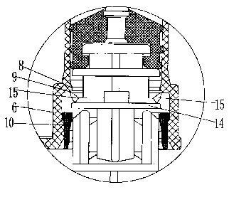
As shown in Fig. 9, the present invention is improved in the following
aspects:
The push rod 2 is provided with a round platform 14, which is provided with an
elastic ratchet 15 that slantingly extends toward the inner wall of the
barrel; the barrel
is provided at the end with an increasing-diameter portion 6; at the transient
position
between the normal-diameter portion 7 and the increasing-diameter portion 6 of
the
barrel is located a slanting step S. below which is a grOove 9 where the
elastic ratchet
15 can be catched when the push rod is drawn backward; and the increasing-
diameter
portion 6 is provided inside with a circlip 10 that can press against the
bottom of the
round platform 14.
As shown in Fig. 10, Fig. 11 and Fig. 15, the push rod 2 is provided below the
rubber plug 3 with a round platform 14, whose external diameter is smaller
than or
equal to the minimal internal diameter of the barrel at the slanting step 8,
but bigger
than the minimal internal diameter of the circlip 10; the round platform 14 is
provided
with an elastic ratchet 15 that slantingly extends toward the inner wall of
the barrel;
4
CA 02724997 2010-11-19
there are at least two elastic ratchets 15 that are symmetrically positioned;
there are
preferably four elastic ratchets 15 that are symmetrically positioned; the
distance
between the symmetrical ratchet tips is smaller than the internal diameter of
the
normal-diameter portion 7 of the barrel, but bigger than the minimal internal
diameter
of the barrel at the slanting step 8; and the tip of the elastic ratchet 15
extends
slantingly up to the front end of the barrel. As shown in Fig. 14, the groove
9 is a
circle of clamping groove along the circumference, whose upper end plane 91 is
a
slope or a plane that extends outward along the direction of the tip of the
elastic
ratchet 15; and the diameter of the groove at the side wall 92 is bigger than
the
distance between the tips of the symmetrically-positioned elastic ratchets 15.
As
shown in Fig. 11 and Fig. 12, the circlip 10, dynamically fitted with the
inner wall of
the increasing-diameter portion 6 at the end of the barrel, can move forward
and
backward axially without moving out of the barrel, with the moving distance
longer
than the distance from the tip of the elastic ratchet 15 on the push rod 2 to
the bottom
of the round platform 14; the upper end of the circlip 10, whose internal
diameter is
slightly smaller than that of the barrel at the slanting step 8, can press
against the
bottom of the round platform 14. The circlip 10 is provided at the inner
circle with a
slope 11; when the push rod is installed, the elastic ratchet 15 can move
forward and
furl inward along the slope, and the round platform 14 can stretch the inner
bore of the
circlip 10 larger and get into it. The increasing-diameter portion 6 at the
end of the
barrel is provided on the inner wall with a circle of big groove 61 that is
dynamically
fitted with the circlip 10; the big groove 61 can butt at its upper end 62
against the top
end 121 of the circlip 10, and is provided at the lower end with a flanged
step 13; the
circlip 10 is provided at the upper outer circle with a flange 12; the flanged
step 13
butts against the bottom end plane 122 of the flange 12; and the step 13
prevents the
circlip 10 from sliding out of the barrel. As shown in Fig. 13, when the push
rod 2 is
drawn backward to the bottom of the barrel after injection, the bottom plane
of the
round platform 14 on the push rod 2 will get in touch with the top plane of
the circlip
10 installed within the barrel 1; since the internal diameter of the circlip
10 is smaller
than the external diameter of the round platform 14, the circlip 10 is brought
to move
backward; when the push rod 2 is drawn further backward, the elastic ratchet
15 will
get in touch with the upper slope 81 of the slanting step 8, experience
elastic
deformation toward the center of the push rod under the action of this slope
81, and
move across the minimal-inner-diameter point of the slanting step 8 along with
the
backward movement of the push rod; the elastic ratchet 15, after moving across
the
=
5
CA 02724997 2010-11-19
point, restores its natural state by its own elasticity, and its tip will get
stuck into the
groove 9 below the slanting step 8; when the push rod 2 continues to move
backward,
the bottom end plane 122 of the flange 12 at the upper end of the circlip 10
will butt
against the flanged step 13 on the inner wall of the increasing-diameter
portion 6 at
the end of the barrel, which may prevent the push rod from moving backward; if
a
certain force is applied to push the push rod forward in the injecting
direction, the
elastic ratchet 15 will prevent the movement under the action of the groove 9;
the side
wall 92 of the groove 9 can prevent the elastic ratchet from overturning along
the wall
of the barrel; and thus the push rod is locked. In order to make the self-
destroying
process more complete, the push rod 2 can further be provided with some
defective
points; in this embodiment, four defective points A, B, C and D are provided;
when
being drawn backward after injection, the push rod 2 may be pulled apart at
the
defective points; since the push rod 2 has been locked this time, it cannot be
reused or
replaced, thus ensuring complete self-destroying of the syringe.
During application of the present invention: First, as shown in Fig. 1 where
the
syringe has not been assembled together, the push rod 2 has not been pushed
into the
barrel yet, and the circlip 10 is limited at the end of the barrel by the
flange 12 on the
inner wall of the barrel. Then, as shown in Fig. 2 where the push rod 2 has
been
installed in the barrel, the elastic ratchet 15 on the push rod 2 moves
forward along the
slope 11 of the circlip 10, and meanwhile the circlip 10 along the inner wall
of the
barrel from the point 61 to the point 62; and the elastic ratchet 15 furls
inward under
the pressure of the circlip 10. As shown in Fig. 3, since the upper end of the
circlip 10,
whose internal diameter is smaller than that of the barrel at the slanting
step 8, the
elastic ratchet 15, under the action of the circlip 10, can smoothly move
through the
slanting step 8 into the normal-diameter portion of the barrel; and the round
platform
14, through stretching the inner bore of the circlip 10 larger, can get into
the
normal-diameter portion of the barrel as well. Fig. 4 shows the syringe that
has taken
in the fluid. Fig. 5 shows the syringe that has finished injection. As shown
in Fig. 6,
the needle seat 4 is apart from the barrel, which is the first step of the
self-destroying
process; this time the push rod is pulled backward, which will bring the
needle seat 4
to retract, and meanwhile the elastic ratchet 15 will slide backward along the
slanting
step 8, as shown in Fig. 7 and Fig. 13; this time the elastic ratchet 15 gets
stuck into
the groove 9 located below the slanting step 8, and the push rod 2 is locked,
thus
completing the self-destroying process. As shown in Fig. 8, the push rod 2 is
pulled
6
CA 02724997 2014-06-05
apart at the defective points, and thus completely destroyed.
In the above technical solution, the syringe in the embodiment adopts the
retractable needle. However, the improved technical solution described in the
present
invention is not limited to this type of syringe, but applicable to other
types of
syringes with nonretractable needles as well. The scope of the claims should
not be
limited by the preferred embodiments set forth in the examples, but should be
given
the broadest interpretation consistent with the description as a whole.
7