Note: Descriptions are shown in the official language in which they were submitted.
CA 02725083 2016-06-17
=
WO 2009/143341 PCT/US2009/044833
TRAYS AND APPARATUS AND METHOD FOR REMOVING CARTONS FROM TRAYS
CROSS-REFERENCE TO RELATED APPLICATION
[0001] Benefit is claimed of U.S. Patent Application Ser. No. 61/054,936,
filed May 21, 2008,
and entitled "APPARATUS AND METHOD FOR REMOVING CARTONS FROM LOAD
BEARING TRAYS".
FIELD OF THE INVENTION
[0002] The present invention relates to the automated handling of cartons
in warehouses and
distribution centers and, more particularly, to the automated removal of the
cartons from load
bearing trays.
BACKGROUND OF THE INVENTION
[0003] Current industry practice to remove cartons automatically from trays
utilizes one of
two types of designs. The first design involves stopping the tray, lifting the
carton up on fingers
and raking the carton off the fingers. This design requires the tray to come
to a stop thereby
limiting the potential throughput rate. In this design, a single tray removal
device can have the
ability to process multiple tray sizes but imposes certain limitations to the
number of sizes of trays
that can be processed by a single tray removal device. It also at times
imposes additional
limitations on the orientation of trays with regard to the side or dimension
of the tray that first
approaches the tray removal device.
[0004] A second design is characterized by previous attempts to utilize a
continuous process
involving a "scraping" type device to lift the carton up and onto a powered
belt. This design
requires a grid of raised platforms on the bottom of the tray. The platforms
form an elevated
surface upon which the carton can rest. The fingers of the scraping device
reach between the
platforms and under the elevated carton. As the tray moves on the powered
belt, the back lip of the
tray drives the carton up the inclined scraper surface formed by the assembly
of fingers and onto a
powered belt. This design requires significantly increased vertical height in
the tray design,
resulting in the tray itself occupying a significant amount of space in the
storage facility. It also
requires the use of relatively uniform size cartons to allow the back edge of
the tray to drive the
carton far enough up the inclined surface to engage the powered takeaway
conveyor. This design
1
CA 02725083 2010-11-19
WO 2009/143341 PCT/US2009/044833
also is limited in that each tray removal device can process only one size
tray thus requiring
multiple devices as a means to process multiple tray sizes.
[0005] The cartons handled by automated systems can vary in size, therefore
it is a goal of
carton removal systems to provide and use trays that are of a size that will
contain the carton but
are no larger than necessary to do so. To the degree that the tray is larger
than the carton, some
space in the storage facility may be wasted. In these applications a wide
variety of carton sizes are
used. In order to maximize the utilization of the storage volume, multiple
tray sizes are required.
SUMMARY OF THE INVENTION
[0006] In one aspect of the invention, there is provided an apparatus and
method for removing
cartons from load bearing trays as the trays move continuously on a generally
planar conveyor
surface.
[0007] The sizes of trays may be chosen to accommodate most efficiently the
sizes of the
individual cartons. The carton removal apparatus can act on the trays and
their contents without
regard to the size of the tray and without regard to the fore and aft
orientation of the trays such that
either end of the tray may approach the carton removal apparatus first.
[0008] The tray provides a means for the apparatus to insert a multiplicity
of acutely sloping
wedges/fingers into generally vertical slots in the leading edge side of the
advancing tray, the slots
extending upward through the top edge of the tray side wall and downward to
join with recessed
grooves in the bottom surface of the tray. The wedges are positioned such that
they insert between
the bottom surface of the carton and the tray surface on which the carton
rests, thereby lifting the
front edge of the advancing carton onto the upper surfaces of the wedges.
[0009] In an exemplary embodiment, the planar upper surface of each wedge
joins with, is
aligned with, and is continued by, a moving conveyor belt of generally the
same width as the
upper surface of the individual wedge. The forward motion of the tray pushes
the carton onto the
upper surface of the wedges to a point at which the bottom surface of the
carton comes in contact
with the multiplicity of moving conveyor belts which then support the carton
and move it forward,
generally independent of the motion of the tray. The carton is supported by
and transported by the
multiplicity of conveyor belts and is thus separated from the tray. The
carton, now removed from
the tray, continues its motion onto a conveyor surface that adjoins the
conveyor belts of the carton
removal apparatus.
2
CA 02725083 2010-11-19
WO 2009/143341 PCT/US2009/044833
[0010] Another aspect of the invention involves a system having a plurality
of trays, each
comprising a base and a pair of end walls extending upward from the base. The
system includes a
tray unloading system. The trays are of a plurality of different widths. The
tray unloading system
comprises a plurality of fingers. Each of the end walls comprises a plurality
of vertical slots open
to an upper edge of the end wall. The fingers are positioned in dimension to
pass through the slots
of the trays as the trays are delivered to lift contents of the trays. The
fingers are positioned so that
some fingers pass through the slots of each of the different tray widths but
others pass only
through slots of wider said tray widths.
[0011] In various implementations, the fingers may be positioned at an
essentially
non-constant spacing effective to accommodate the different widths. The
fingers may be laterally
asymmetrically positioned. The non-constant spacing may comprise: a first
group at a
non-constant first on-center pitch; and a plurality of additional fingers
separated from the first
group by one or more gaps. The plurality of additional fingers may comprise a
single intermediate
finger separated from the first group by a first gap at an on-center dimension
other than a multiple
of said first on-center pitch and at least two more fingers separated from the
intermediate finger by
a second gap at an on-center dimension other than a multiple of said first on-
center pitch. The first
group may consist of five fingers. The at least two additional fingers may
consist of said two
additional fingers at said first on-center pitch.
[0012] The fingers each may comprise a tip member and a conveyor and may be
positioned to
guide the contents to a tray content removal conveyor. The finger conveyors
may be powered in
common by a motor.
[0013] Further aspects involve the method for operating such a system. A
tray delivery
conveyor is driven to move the trays downstream to the transfer system. At
least some of the
fingers are passed through the slots of the trays as the trays are delivered
by a tray delivery
conveyor. The passing includes passing the tip members through a leading one
of the end walls of
each tray and passing the tip members into grooves in the base of each tray
and below the
contents, a wedging action of the tip members providing an initial said lift
of the contents of the
trays. The contents are passed along the fingers to the finger conveyors. The
finger conveyors are
driven to transfer the contents to a tray content removal conveyor. The tray
content removal
conveyor is driven to further transport the contents. A trailing one of the
end walls may push the
contents up the tip portions or notches in a tray base may do so. The fingers
may pass
inside-to-outside through the trailing end wall. There may be a plurality of
different widths of the
3
CA 02725083 2010-11-19
WO 2009/143341 PCT/US2009/044833
trays. A partially different group of the fingers may pass through the slots
respectively of the trays
of different widths.
[0014] The different tray widths may include at least first, second, and
third widths. The
fingers may be positioned at a spacing effective to accommodate the different
widths as firsts of
the first side walls of the trays pass in a predetermined alignment with a
first edge of the conveyor
so that: the first width is accommodated by a first terminal group of the
fingers passing through
associated ones of the slots with the second side wall passing through a first
gap between the first
terminal group and a remainder of the fingers; the second width is
accommodated by the first
terminal group of the fingers and at least one of the remainder passing
through associated ones of
the slots with the second side wall passing through a second gap between the
at least one of the
remainder and remaining fingers of the remainder; and the third width is
accommodated by the
first terminal group of the fingers and at least two of the remainder passing
through associated
ones of the slots.
[0015] Further aspects of the invention involve trays. Each tray comprises
a base and a pair of
end walls extending upward from the base. The base includes an upper surface
having a plurality
of interspersed longitudinal grooves and ridges. Each of the end walls
comprises a plurality of
vertical slots open to an upper edge of the end wall and respectively aligned
with an associated
said groove. There may be at least two distinct lateral sizes of the slots and
grooves. In various
implementations, the tray may be a nineteen inch wide tray having exactly
seven said slots and
grooves or the tray may be a twenty-six inch wide tray having exactly ten said
slots and grooves.
The tray may have exactly seven said slots, a central group of three of the
slots having larger slot
width than the two terminal pairs of two slots or the tray may have exactly
ten said slots and
grooves, two terminal groups of three slots having slot width less than the
respective adjacent slots
separating the two terminal groups from a central pair of slots.
[0016] Such a system may have one or more of the following advantages.
= One advantage is the ability to remove the carton from the tray while the
tray remains in
motion, thereby removing a greater number of cartons in a specific period of
time.
= Another advantage is the ability to use a greater variety of tray sizes
than previous systems,
each tray being chosen to fit most closely the carton that is placed on it,
thereby making
more efficient use of space within the storage facility.
= Another advantage is the reduction in the thickness, or vertical height,
of the bottom
surface of the tray, such that the tray occupies a minimum of space beyond
that which is
4
CA 02725083 2016-06-17
=
WO 2009/143341 PCT/US2009/044833
required to contain the carton, thus making more storage space within the
storage facility
available for storage of cartons.
= Another advantage is the ability to handle multiple trays sizes in a
single apparatus,
thereby possibly reducing the number of devices required.
= Another advantage is an improved method of stacking empty trays on each
other whereby the
space required within the storage facility for the storage of empty trays is
reduced.
= Another advantage is a process for automatic, unattended removal of
cartons from a plurality
of predetermined tray sizes, wherein the movement of the trays is continuous
and without
interruption, by a single carton removal apparatus.
100171 The details of one or more embodiments of the invention are set
forth in the
accompanying drawings and the description below. Other features, objects, and
advantages of the
invention will be apparent from the description and drawings.
CA 02725083 2010-11-19
WO 2009/143341 PCT/US2009/044833
DESCRIPTION OF THE DRAWINGS
[0018] FIG. 1 is a view of a first (relatively small) tray.
[0019] FIG. 2 is a top view of the tray of FIG. 1.
[0020] FIG. 3 is a bottom view of the tray of FIG. 1.
[0021] FIG. 4 is a side view of the tray of FIG. 1.
[0022] FIG. 5 is an end view of the tray of FIG. 1.
[0023] FIG. 6 is a vertical longitudinal sectional view of the tray of FIG.
1, taken along line
6-6 of FIG. 2.
[0024] FIG. 7 is a view of a second (intermediate) tray.
[0025] FIG. 8 is a top view of the tray of FIG. 7.
[0026] FIG. 9 is a view of a third (relatively large) tray.
[0027] FIG. 10 is a top view of the tray of FIG. 9.
[0028] FIG. 11 is a composite view superimposing end views of the first,
second, and third
trays, in alignment with fingers of a detraying apparatus.
[0029] FIG. 12 is a view of a conveyor system including a detraying
apparatus.
[0030] FIG. 13 is a top view of a defraying apparatus.
[0031] FIG. 14 is a front view of the apparatus of FIG. 13.
[0032] FIG. 15 is a side view of the apparatus of FIG. 13.
[0033] Like reference numbers and designations in the various drawings
indicate like
elements.
6
CA 02725083 2010-11-19
WO 2009/143341 PCT/US2009/044833
DETAILLED DESCRIPTION
[0034] One embodiment of a tray 20 is shown in Fig. 1. The tray has a base
22 and
circumscribing wall structure 24 extending from a junction 25 with perimeter
of the base to an
upper rim 26. The wall structure includes two sloping, continuous and
generally vertical sides
(side walls) 28 and two generally vertical slotted ends (end walls) 30. The
sides 28 and ends 30
extend to upper edges formed as portions of the rim 26. The base 22 has an
underside or bottom
32 (FIGS. 3&4) which forms a tray bottom and has an upper surface or top side
34 (FIG. 5) which
may support one or more cartons 36 contained within the wall structure.
[0035] The base has upwardly-open channels or grooves 38 (FIG. 2) which run
from end to
end, joining each end 30 at the base of a slot 40. The grooves 38 separate and
are interspersed with
ridges or lands 42. The base has upwardly-open transverse notches 44 passing
from side to side
along each of the ridges. The exemplary notches 44 are shallower than the
grooves 38. The
exemplary wall structure 24 has an inboard face/surface 50 and an outboard
face/surface 52 each
with respective portions along the sides 28 and ends 30 to form inboard and
outboard surfaces
thereof The exemplary trays are of substantially rectangular planform having
an overall width Wi
and an overall length Li. Additionally, the tray has an interior width W2 and
length L2 (measured
as associated widths and lengths of the largest rectangular carton which may
be supported on the
upper surface of the base). An exemplary overall/exterior tray height is shown
as Hi from the
underside of the base to the upper rim 26. An exemplary base thickness/height
is H2, leaving an
interior depth/height of H3 equals Hi minus H2. For reference, a longitudinal
vertical medial plane
is shown as 500 and a transverse vertical medial plane is shown as 502. The
sides and ends of the
tray slope outward slightly so that when trays are stacked on each other, the
space required for
storage of trays is kept needed. The outboard surface 52 is stepped (FIG. 4)
with an upwardly
divergent angled lower portion 55, a vertical upper portion 56, and an
intermediate wedge 57
joining the upper and lower portions. When stacked, the trays nest with the
intermediate portion
57 contacting or closely facing the upper rim 26 of the wall of the tray
immediately below.
[0036] The slots 40 extend along/through the end walls 30 and are open
to/at the upper edges
of the end walls. The slots separate interspersed intact portions 60 of the
end walls. The slots 40
and their associated grooves 38 are positioned and dimensioned to accommodate
fingers
(discussed below) of a defraying system for removing cartons. The exemplary
slots/grooves each
have a characteristic width W3. The slots/grooves separate intact end wall
portions 60 and ridges
42 having a width W4. An on-center spacing Si of the slots/grooves is measured
as half of the
7
CA 02725083 2010-11-19
WO 2009/143341 PCT/US2009/044833
respective width W3 of each two adjacent such slots/grooves plus the width W4
of the intervening
intact end portions/ridges. Similarly, an on-center spacing S2 of the intact
end portions/ridges is
half of the respective widths W4 of two adjacent such end portions/ridges plus
the width W3 of the
intervening slot/groove. As is discussed further below, the widths W3 and W4
and spacings Si and
S2 can vary for the different slots/grooves and intact end wall
portions/ridges. In the exemplary
tray, respective left and right terminal portions 64 of the intact end walls
(of associated corner
portions 66 of the wall structure) have widths W5 which are greater than W4.
This allows for
relatively robust corner portions. This robustness may provide one or more of:
lateral support of
the side walls; vertical strength for stacking; longitudinal strength for
retaining tray contents; and
surface area for bar codes/labels/other indicia.
[0037] It is desirable to provide operation with multiple sizes of trays.
Different tray lengths
may readily be accommodated. However, accommodating different tray width
creates problems.
The exemplary tray 20 has five grooves/slots. If a larger tray were to merely
be a laterally
extended version (having more slots of the same width and spacing), there
would be problems
accommodating both trays. Specifically, if the detraying machine had fingers
positioned to engage
the slots of the larger tray, those fingers would interfere with one of the
corner portions 66 of the
smaller tray. Accordingly, as is discussed in further detail below, the basic
tray of FIG. 1 can form
one part of a system where a more complicated arrangement of defraying machine
fingers are
provided along with a more complicated distribution of slots in larger trays.
An example is
described below wherein the tray of FIG. 1 is the smallest of three exemplary
sizes (more
particularly, widths) of tray.
[0038] FIGS. 7&8 show an exemplary intermediate/medium size tray 20' and
FIGS. 9&10
show an exemplary large tray 20" in the three-width system. As is discussed
further below, each of
the trays is of generally similar construction with similar relatively wide
corner portions but with
different groove/slot distribution. The variation in groove/slot distribution
may best be visualized
by first looking at the finger distribution of the detraying machine.
[0039] Exemplary exterior dimensions Li and Wi of the tray 20 are nineteen
inches (48cm)
and fourteen inches (36cm) and inside dimensions L2 and W2 are seventeen
inches and twelve
inches. For the medium tray 20' these are: twenty-six inches (66cm); nineteen
inches; twenty-four
inches (61cm); and seventeen inches. For the large tray 20" these are: forty-
one inches (104cm);
twenty-six inches; thirty-nine inches (99cm); and twenty-four inches. These
interior dimensions
are as measured at the interior base of the side walls. Each of the three
sizes has overall height H1
8
CA 02725083 2010-11-19
WO 2009/143341 PCT/US2009/044833
of an exemplary three inches (8cm). The base height H2 of each size tray is an
exemplary 0.75
inch (2cm), and interior depth H3 of an exemplary 2.25 inches (6cm). These
different sizes are
similar in form but vary from each other, in addition to overall size, in the
number and distribution
of slots and the corresponding grooves. As is discussed further below, each
tray has mirror image
symmetry across the planes 500 and 502. Thus, each tray can be processed with
either end leading.
[0040] The device is not limited to the use of only three sizes of trays
and alternative
embodiments could have more or fewer tray sizes and could use sizes different
from those of the
exemplary embodiment. The exemplary trays are made of plastic (e.g., a single-
piece unitary
polypropylene molding) of sufficient strength to bear the load of the cartons
but alternative
embodiments could be made of different plastics, metal or other materials.
[0041] FIG. 11 shows an end view of three sizes of trays 20, 20', and 20",
and the relationship
the slots in each size tray bear to the vertical slots of the other size trays
and to fingers of a
detraying machine 200.
[0042] As is discussed further below, the detraying machine forms a portion
of a transfer
system for transferring cartons from the trays. The fingers are positioned to
pass partially through
the associated tray slots and grooves to remove (detray) the cartons from the
trays. The exemplary
machine 200 has nine fingers labeled 202A-2021. These nine fingers are
configured for use with
an exemplary four-tray system including a fourth tray (not shown) even wider
than the tray 20".
The first eight fingers 202A-202H, alone, facilitate use of the three-tray
system. In the exemplary
system 200, the trays pass along a conveyor system with a first side 28 in a
predetermined lateral
registry with the system 200 (e.g., against a first side 204 of a conveyor
carrying the trays and
their cartons). As the small tray 20 passes through the system, a first
terminal group (i.e., starting
from one side of the array of fingers) 202A-202E of an exemplary five of the
fingers passes
through respective slots/grooves (for purpose of reference, the slots 40 being
subreferenced
40A-40E but the grooves 38 not being individually referenced). Each of the
fingers is shown
having a width W10. An on-center spacing Si0 is also shown between adjacent
fingers (and
subreferenced S 1116,-S 10H for the respective pairs of fingers). A gap width
between fingers is shown
as W11. As is discussed further below, the spacing or pitch S10 for the group
of fingers 202A-202E
may be constant or close thereto. FIG. 11 shows respective inter-finger gaps
210A-210H. The
width W11 of the gap 210E is substantially larger than the width of the gaps
210A-210D within the
first group of fingers 202A-202E. This gap is effective to accommodate the
second side wall and
associated corners of the small tray 20. This gap width may be more than twice
the width of the
9
CA 02725083 2010-11-19
WO 2009/143341 PCT/US2009/044833
gaps 210A-210D. As is discussed further below, the gap 210E may represent
approximately the
loss of a single finger from an array of constant spacing. However, the
spacers may be further
modified to improve coverage and feeding. For example, in the Table below, two
examples are
given one with exactly constant spacing of the first five fingers and the
other with a slightly
increased spacing between the third and fourth and a correspondingly slightly
decreased spacing
between the fourth and fifth. This may improve feeding consistency when the
various sizes of
trays are considered.
[0043] For removing cartons from the intermediate/medium tray 20', the
first group of fingers
202A-202E are used along with the next finger 202F. These respectively pass
through slots
40'A-40'E and 40'G (and their associated grooves) of the tray 20'. No finger
passes through the
penultimate slot 40'F. The slot 40'F exists for side-to-side symmetry (so that
it would be in the
position of slot 40'B if the tray is reversed). This symmetry allows trays to
be used in either of two
orientations. When passing the medium tray, its second side wall and
associated corner portions
pass through the gap 210F. Thus, the gap 210F may be of similar dimension to
the gap 210E.
[0044] Similarly, for removing cartons from the large tray 20", the first
group of fingers
202A-202E are also used along with the next finger 202F and the next two
fingers 202G and
202H. These respectively pass through slots 40'A-40'E, 40'G, 40'1, and 40'J
(and their associated
grooves) of the tray 20". No finger passes through the slots 40'F and 40'H.
These slots 40'F and
40'H exist, as noted above, for side-to-side symmetry (so that they would be
in the positions of
slots 40'E and 40'C if the tray is reversed as in a mirror image across the
plane 500). When passing
the large tray, its second side wall and associated corner portions pass
through the gap 210H.
Thus, the gap 210H (if a finger 2021 is present) may be of similar dimension
to the gaps 210E and
210F.
[0045] Exemplary slot and/or groove width may be measured at a given
particular height or
heights or as an average (e.g., a mean, a median, or a mode). This width is
shown as essentially
constant along the grooves and essentially constant along a lower/proximal
portion of the intact
wall portions (e.g., to about the level of the base upper surface). Thus, the
intact wall portions'
widths may similarly be measured. Exemplary slots diverge upwardly/distally.
Accordingly, the
exemplary intact wall portions converge upwardly/distally along upper/distal
portions thereof.
Exemplary finger spacing and slot width are shown in Table 1 where widths are
measured along
the lower/proximal portions. Example 1 repeats dimensions from the drawings of
the priority
application.
CA 02725083 2010-11-19
WO 2009/143341 PCT/US2009/044833
Table 1
Dimensions in inches
Dimension Ex.1 Ex.2
S 10A 2.25 2.25
S 10B 2.25 2.25
Sick 2.25 2.38
S 10D 2.25 2.12
S 10E 4.9 4.9
S 1 OF 4.75 4.75
S 10G 2.25 2.25
S 10H - 4.24
W1 14.1 14.1
W'i 19.0 19.0
26.0 26.0
W3A-F 1.25 1.24
W'3A,B,F,G 1.24
W3C-E 1.64
Wu3A-C,E,F,H-J 1.24
Wu3D&G 1.49
W4 1.0 1.08
W5 1.92 1.93
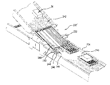
[0046] FIGS. 12-15 show an exemplary eight-fingered machine 200' as part of
a system
including a tray delivery conveyor 240 and a tray content (carton) removal
conveyor 242. Each
finger is shown including an associated wedge-like tip 244. These tips 244 are
sized to be a close
but non-interfering fit in the grooves in the base of the approaching tray.
The bottom surface 246
of each wedge/tip is oriented such that it is generally parallel to the upper
(transport) surface of the
conveyor 240 transporting the tray and is positioned a sufficient distance
above conveyor 240 for
the base of the tray along the grooves to pass below the wedge. The upper
surface 246 of each
wedge/tip slopes at an angle acute enough that the wedge can slip between the
moving tray and the
bottom surface of the carton carried by the tray, and is positioned to insert
into the cavity formed
11
CA 02725083 2010-11-19
WO 2009/143341 PCT/US2009/044833
by the groove in the base of the tray below the carton. Exemplary wedges/tips
are arranged
parallel to each other so that their upper surfaces combine to form a ramp up
which the carton can
be pushed by the movement of tray. The exemplary fingers each also have a
conveyor belt 252 for
transferring the cartons to the conveyor 242. Each finger may also include a
strut 258 (FIG. 15)
supporting the wedge and at least partially supporting the associated conveyor
252. A platform
260 may replace or span the struts at a height sufficiently above the conveyor
240 to allow the
trays to pass below a leading edge 262 of the platform. The exemplary wedges
have sufficient
length so that the movement of the tray will drive the cartons up the wedges
until the bottom
surface of a leading portion of the carton comes into engagement with some or
all of the conveyor
belts 252.
[0047] A small carton may be pushed forward and up the ramp (formed by the
wedges/tips)
primarily by friction between the bottom of the carton and the tray. The
notches 44 in the ridges in
the tray bottom are provided to supplement this friction and the rear/trailing
end wall of the tray
acts as a positive stop should the carton slide on the tray and not be
captured by the notches. For a
relatively large carton (e.g., one that longitudinally fills the tray) the
engagement may merely be
with the rear/trailing end wall. As the carton is pushed far enough onto
conveyor belts 252 by the
motion of tray, a point is reached wherein the friction between belts and the
bottom surface of
carton is sufficient for the carton to be moved by belts without regard to the
motion of the tray and
the carton is pulled away from the tray. This may offer a benefit over prior
systems by placing the
point at which control of the carton passes from the tray to the carton
removal apparatus earlier in
the removal process. Extending the belts 252 through the slots 40 reaching
below the top of the
end wall of the tray and into the interior space of the tray may facilitate
this.
[0048] FIG 13 shows that each strut member 258 extending from a common
drive shaft 270 at
the carton output end to an idler pulley 272 (FIG. 15) at the intake end where
the wedge/tip is
attached. Each strut holds its wedge/tip in position and additionally provides
support for its belt as
the assembly of belts supports the weight of the carton. A motor 274 and its
connection with shaft
27 may be standard items typically used in conveyors.
[0049] Trays arrive at the apparatus on the conveyor 240. This conveyor is
an item that is
presently available from one or more sources and is of the type that, as it
conveys the tray, also
moves the tray to the right relative to the direction of travel so that the
tray is in contact with the
side wall 204 of the conveyor when it arrives at the tray unloading machine.
This ensures a
12
CA 02725083 2016-06-17
WO 2009/143341 PCT/US2009/044833
predictable positioning of the tray as it approaches the unloading machine,
thus aligning the slots in
the end of the tray with the wedges so that the wedges can enter the slots.
[0050] The assembly of conveyor belts 252 is powered by the motor 274
acting through the
shaft 220 such that the belts move in the same direction as the conveyor
mechanism 240 and they
move at a speed that is generally equal to or greater than that of the
conveyor 240. Trays
containing cartons arrive at the unloading machine on conveyor 240. After a
carton is removed
from a tray, the unloading machine moves the carton onto the conveyor 242.
Empty trays continue
on the conveyor 240. The exemplary conveyor 240 is generally horizontal and
conveyor 242 is on
an incline leading up and away from the unloading machine. Alternative
embodiments could vary
such that the conveyor 240 slopes downward into the unloading machine with the
conveyor 242
being generally level, or could also be such that both conveyors are on an
incline or both are
horizontal.
[0051] In use, the tray unloading machine operates in an unattended fashion
and enables the
following process. Trays containing cartons approach the apparatus on a
conveyor. Each tray may be
one of multiple predetermined sizes and the carton carried by the tray can
vary in size and weight.
Additionally, either end of the tray can approach the apparatus first. Without
interrupting the
continuous motion of the carton, the apparatus removes the carton from the
tray, allowing the now
empty tray to continue in motion and it moves the carton onto a separate
conveyor for continued
processing.
[0052] One or more embodiments of the present invention have been
described. Nevertheless, it
will be understood that various modifications may be made without departing
from the scope of the
invention. For example, when applied to different existing warehouse
environments (e.g., conveyor
systems, etc.) details of such environments will influence details of any
particular implementation.
13