Note: Descriptions are shown in the official language in which they were submitted.
CA 02725098 2010-11-19
WO 2009/143262 PCT/US2009/044702
ADJUSTABLE MOLD AND ASSOCIATED METHOD FOR MAKING A DRAINAGE
CHANNEL
FIELD
This invention relates generally to drainage channels and trench-forming
adjustable
molds, and to a method and system for using the adjustable molds to create
different-sized
drainage channels.
BACKGROUND
Drainage and other trenches of various sizes and shapes are desirable for a
number of
applications. For example, manufacturing facilities typically require drainage
systems that
include trenches formed in the building floors to collect, remove, and/or
recycle excess water or
other liquids. These trenches may also be used as utility chases to provide
temporary or
permanent routing of electrical lines, pipes, conduits or the like below the
level of the building
floor. In addition, numerous outdoor industrial and commercial sites, such as
parking lots, also
require drainage systems, including trenches, to collect and direct rainwater
and other liquids to
underground storm sewers to prevent flooding and to decrease run-off.
Similarly, roadways and
the like may also require drainage systems, including trenches.
In the past, these trenches have generally been formed by first placing and
securing a
form of predetermined shape in a ditch that has previously been formed in the
ground. A
moldable trench-forming composition, such as cementitious material or polymer
concrete, is then
poured around the form and is allowed to set. Once the material has set, the
form is removed
from the resulting trench.
1
CA 02725098 2010-11-19
WO 2009/143262 PCT/US2009/044702
One type of form assembly used to define a trench includes a wooden form and
strut
structure. The wooden form includes a wooden frame which is covered with
wooden sheets or
planks to define a generally rectangular elongated trough. The wooden form is
typically
enclosed along its side and bottom faces, but may have an open top. Typically,
a number of
supporting wooden ribs are installed within the wooden form to increase the
strength of the form
so that it can withstand the relatively large pressures exerted by moldable
trench forming
compositions poured about it.
The wooden form is placed and secured within a preformed ditch. Cementitious
material
is typically poured up to the bottom face of the form and allowed to set in
order to anchor the
wooden form in the ditch. Then, additional cementitious material is poured
between the earthen
walls of the ditch and the wooden sides of the form. Once all of the
cementitious material has set,
the wooden form is disassembled and removed from the trench.
Wooden forms are generally formed of lumber having a relatively rough exterior
texture.
Correspondingly, the inside surface of the trench formed by the wooden form is
relatively
uneven which reduces the efficiency of the flow of liquid through the trench.
In addition, the
assembly and disassembly of the wooden forms is both costly and labor
intensive. The relatively
large cost and labor required for assembly and disassembly of the wooden forms
is increased in
the formation of long trenches, and even further increased in the formation of
trenches having a
pitched or slanted bottom surface to facilitate drainage.
Inexpensive forms are employed to form trenches instead of using the wooden
forms
discussed above. These trench-forming assemblies preferably include opposing
longitudinal
frame members having a plurality of anchoring rods extending downwardly from
the frame
2
CA 02725098 2010-11-19
WO 2009/143262 PCT/US2009/044702
members. An elongated form body, preferably formed of relatively lightweight
expanded
polystyrene, includes aligned longitudinal slots in the opposed side walls for
receiving the frame
members. Horizontal portions of the frame members are secured within the
longitudinal slots in
the sidewalls of the form body during formation of the trench so that the
frame members are held
in alignment during the trench forming operation.
Preferably the assembled form and frame members are placed into a prepared
ditch by
suspending the assembly from its top, such as by one or more batter boards.
Cementitious
material is first poured around the bottom of the anchoring legs attached to
the frame members
and allowed to set in order to secure the anchoring legs and, in turn, the
frame members and the
form within the ditch. Then more cementitious material is poured around the
form body and
allowed to set. Finally the form body is removed to expose the resulting
trench and the properly
aligned frame members. The removal of the form may be facilitated by a pair of
slots extending
upwardly into the form body from its bottom surface. By removing an upper
portion of the form
to access the slots, the form body can be more easily removed from the trench
in several pieces.
Drainage channels may also come preformed and assembled on site from a series
of
discrete drainage channel sections which form and provide a chemical resistant
liner in the
trench. A first step in installing such a drainage channel is placing the
drainage channel sections
in an end-to-end relationship at the proper depth below the desired level of
the surface. In this
regard, a trench may be formed to the desired depth adjacent to the surface
for receiving the
channel sections. Alternatively, the entire area below the surface may be
graded to the desired
depth and various subsurface layers can then be placed thereon.
3
CA 02725098 2010-11-19
WO 2009/143262 PCT/US2009/044702
The adjacent ends of two adjoining drainage channel sections may have
interlocking end
surfaces and may be supported on a single support brick which has been aligned
and secured
before placement of the drainage channel sections. It is important that the
channel sections be
supported in such a manner that the channel sections are precisely aligned so
as to ensure proper
drainage, to permit the grate to seat properly over the open top of the
drainage channel, and to
prevent adjoining channel sections from being misaligned so as to create a
potential trip hazard
for people. This proper alignment of the drainage channel sections can be
thwarted even if the
support bricks are properly aligned if the drainage channel sections and, more
particularly, the
respective lower surfaces of the drainage channel sections which are seated
upon the support
bricks are not properly formed in a predetermined aligned relationship. Once
the adjoining
drainage channel sections have been interlocked, however, the adjacent ends of
the sections may
be sealed with an adhesive or sealant to prevent leakage.
Once the drainage channel sections are interlocked in an end-to-end
relationship, the
lower portions of the drainage channel sections are typically encased in
concrete so as to secure
the channel.
Regardless of the fabrication technique, it is normally desirable to finish
the trench with
an elongated grate covering its open top in order to prevent people from
unwittingly stepping in
the open trench, to provide a smooth surface for vehicle travel, and/or to
prevent relatively large
objects from entering the trench and potentially blocking the flow of liquid
therethrough. The
grate is generally supported by a pair of spaced apart frame members which are
set into and
extend from the walls of the concrete trench. In order to stabilize the grate
and to prevent the
grate from rocking when weight, such as from a passing vehicle, is applied
thereto, the frame
members must be aligned in a common plane during the pouring and setting of
the concrete
4
CA 02725098 2010-11-19
WO 2009/143262 PCT/US2009/044702
about the form. If the frame members and, in turn, the grate are not properly
aligned, the grate,
the frame members and/or the cementitious trench itself may be damaged by the
resulting
movement of the grate. Accordingly, the alignment of the frame members in the
moldable
trench forming composition is important.
The problem with the pre-formed drainage channels is the fact that customized
molds
must be made for each new customer who needs drainage channels of different
widths, depths,
thicknesses, and slopes. A new custom mold has to be created for each customer
based on the
particular customer's requirements and on the application for which the
drainage channel is
going to be used. In many cases each individual customer themselves will have
a need for a
number of different molds, one for each individual section of the drainage
channel that has a
different depth or slope in its walls. The cost of building, maintaining, and
storing a lot of
molds, many of which are only used once, is significant. Therefore it is
desirable to control and
reduce the number of molds that must be created.
BRIEF SUMMARY
Embodiments of the present invention allow for the manufacture of a number of
drainage
channels of different heights, widths, thicknesses, shapes, and slopes from
only one mold or a
greatly-reduced number of molds. Embodiments of the present invention
facilitate the
manufacturing of custom channels at low cost by reducing the need to develop
and store
individual molds for each type of drainage channel.
In one embodiment, the drainage channel mold has an interior mold and an
exterior mold.
The exterior mold has two opposing sidewalls that can be placed at different
distances apart from
one another to vary the overall width of the drainage channel. The sidewalls
can be independent
CA 02725098 2010-11-19
WO 2009/143262 PCT/US2009/044702
of each other, or they can be coupled to each other yet still allowed to be
positioned at different
distances apart. Alternatively, one sidewall can be fixed while the other can
be positioned at
different distances relative to the fixed sidewall. In another embodiment the
sidewalls are
coupled to a base support that braces the mold assembly. The base support
helps hold the mold
assembly together when in use and allows the mold assembly to be positioned in
different
locations to facilitate its use.
The exterior mold also has two opposing endwalls. In one embodiment the
endwalls are
independent of the rest of the mold. In another embodiment the endwalls are
coupled to the base
support. In one embodiment, one endwall has an embossed edge and the other
endwall has a
recessed area around the periphery, which creates tongue and groove channels
on opposite ends
of the drainage channel for assembly with other sections during installation.
The interior mold can be switched out of the assembly to change the thickness
and
internal shape of the drainage channel. In one embodiment of the invention the
interior and
exterior molds create no ribs in the sidwalls. This configuration results in
reduced stress
concentration in the drainage channel, which reduces the material cost to
obtain the same
strength in the drainage channel. Additionally, the molds can be configured to
introduce a
tapered thickness in the sidewalls to provide strength where needed in the
drainage channel,
which again reduces the material cost.
One embodiment of the mold is an assembly configuration that contains mold
spacers
located between the interior mold and the exterior mold sidewalls. Different
types of mold
spacers can be introduced to the mold to create different heights, widths,
shapes, and slopes in
the walls of the drainage channel formed from the adjustable mold. Another
embodiment
6
CA 02725098 2010-11-19
WO 2009/143262 PCT/US2009/044702
contains adjustable mold spacers. In such an embodiment, the mold spacers can
be adjusted
along the axis of the side walls to vary the height of the drainage channel on
either one or both
sides of the channel. In another embodiment the opposing ends of each mold
spacer may be
movable relative to each other in order to create a drainage channel with a
sloped height. The
sloped height allows for the movement of water from one end to the other or is
helpful for
installation in sloped terrain.
In one embodiment, the mold spacers have recesses for attaching inserts. When
material
is poured into the mold the inserts create recesses in the edges of the
drainage channel walls. In
one embodiment these recesses in the edges of the drainage channel provide
attachment locations
for the grate coverings once the drainage channel is installed into the
ground.
The drainage channel mold of the present invention can therefore use the same
exterior
mold with a number of exchangeable interior molds to vary the width, height,
thickness, internal
surface, and slope of the drainage channels. Alternatively, or in addition to
exchanging the
interior molds, the mold spacers can be replaced or adjusted to vary these
characteristics of the
drainage channels. Therefore, using embodiments of the present invention,
customized drainage
channels can be made for a number of different applications without having to
develop, procure
and store customized molds for each new application, thus, saving time and
money in the
development of customized drainage channels.
In this regard, embodiments of the present invention also provide methods of
making
drainage channel sections of various sizes, shapes, or slopes. For example, in
one embodiment,
the method involves the steps of. (1) providing an adjustable mold having an
interior mold
portion and an exterior mold portion at least partially surrounding said
interior mold portion; (2)
7
CA 02725098 2010-11-19
WO 2009/143262 PCT/US2009/044702
using the adjustable mold to form a first drainage channel section; and (3)
using at least the
exterior mold portion from the adjustable mold to form a second drainage
channel section having
a size, shape, or slope that is different from the first drainage channel
section. In one
embodiment, using at least the exterior mold portion from the adjustable mold
to form a second
drainage channel section involves using both the exterior and interior
portions of the adjustable
mold to form the second drainage channel section having a size, shape, or
slope that is different
from the first drainage channel section. In another embodiment, however, the
method may
involve providing a second interior mold portion that is different from the
first interior mold
portion and using the second interior mold portion in conjunction with the
exterior mold portion
instead of the first interior mold portion so that the exterior mold portion
at least partially
surrounds the second interior mold portion.
As described above, in some embodiments of the invention the adjustable mold
includes
first and second opposing sidewalls supported by a base support, where the
first sidewall is
hingedly coupled to a first portion of the base support, the second sidewall
is hingedly coupled to
a second portion of the base support, and the base support is structured such
that the first portion
of the base support can move relative to the second portion of the base
support to allow the first
sidewall to be moved towards or away from the second sidewall. In such an
embodiment, the
process of using at least the exterior mold portion from the adjustable mold
to form a second
drainage channel section may further involve moving the first sidewall
relative to the second
wall so that the second drainage channel has a width that is different from
the width of the first
drainage channel.
As also described above, some embodiments of the invention the include mold
spacers
that define a distance between said exterior mold portion and the first or
second interior mold
8
CA 02725098 2010-11-19
WO 2009/143262 PCT/US2009/044702
portions, and define the upper edge of walls of the drainage channel sections.
Where these mold
spacers are adjustably moveable relative to the interior and exterior mold
portions, the process of
using at least the exterior mold portion from the adjustable mold to form a
second drainage
channel section may further involve moving the mold spacers relative to the
exterior mold
portion so that the second drainage channel has a height that is different
from the height of the
first drainage channel. Alternatively or additionally, the process may also
involve changing the
slope of the mold spacers relative to the exterior mold portion so that the
second drainage
channel has a slope that is different from the slope of the first drainage
channel. In other
embodiments, however, the process involves replacing the original mold spacers
used in the
adjustable mold to make the first drainage channel section with mold spacers
that are different in
size or shape than the original mold spacers.
BRIEF DESCRIPTION OF THE DRAWINGS
Having thus described embodiments of the invention in general terms, reference
will now
be made to the accompanying drawings, which are not necessarily drawn to
scale, and wherein:
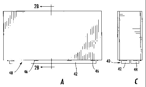
Figure 1 illustrates an isometric plan view of an assembled adjustable
drainage channel
mold configured in accordance with an embodiment of the present invention;
Figure 2(a) is a side view of the adjustable mold of Figure 1 in accordance
with an
embodiment of invention;
Figure 2(b) is a cross-sectional view of the adjustable mold of Figure 2(a)
illustrating the
cavity created by the assembled adjustable mold in accordance with an
embodiment of the
invention;
Figure 2(c) is an end view of the adjustable mold of Figure 2(a) in accordance
with an
embodiment of the present invention;
9
CA 02725098 2010-11-19
WO 2009/143262 PCT/US2009/044702
Figure 3(a) is a side view of the adjustable mold of Figure 1 in accordance
with an
embodiment of the invention;
Figure 3(b) is a top view of the adjustable mold of Figure 3(a) illustrating
where the
material is poured into the mold which then hardens to created the drainage
channel in
accordance with another embodiment of the present invention;
Figure 3(c) is a bottom view of the adjustable mold of Figure 3(a)
illustrating the base
members attached to the opposing side walls and supporting the assembly of the
adjustable mold
in accordance with an embodiment of the present invention;
Figure 4 illustrates an isometric view of an adjustable drainage channel with
the opposing
sidewalls in an open configuration in accordance with an embodiment of the
present invention;
Figure 5(a) is an isometric view of the drainage channel created by one
embodiment of
the present invention;
Figure 5(b) is a front view of the drainage channel of Figure 5(a) created by
one
embodiment of the present invention and illustrates an embodiment of the
drainage channel
having walls with no ribs, thicker drainage base walls, and a shape that
reduces the stress
concentration in the drainage channel walls;
Figure 5(c) is a top view of the drainage channel of Figure 5(a) illustrating
the tongue and
groove edges of the drainage channel formed by the endwalls of the mold
assembly in
accordance with one embodiment of the present invention;
Figure 6 illustrates an isometric view of one side of the adjustable mold
showing one
sidewall of the outer mold, the inner mold, and the spacers in accordance with
an embodiment of
the present invention; and
CA 02725098 2010-11-19
WO 2009/143262 PCT/US2009/044702
Figure 7 is an isometric view of an embodiment of the drainage channel
illustrating the
tongue and groove edges of the drainage channel formed by the mold endwalls,
and the insert
recesses used for assembly during installation of the drainage channel formed
by the mold
assembly spacers and inserts.
DETAILED DESCRIPTION OF THE PREFERRED EMBODIMENTS
Embodiments of the present invention now will be described more fully
hereinafter with
reference to the accompanying drawings, in which some, but not all,
embodiments of the
invention are shown. Indeed, the invention may be embodied in many different
forms and
should not be construed as limited to the embodiments set forth herein;
rather, these
embodiments are provided so that this disclosure will satisfy applicable legal
requirements. Like
numbers refer to like elements throughout.
Referring to the drawings, Figure 1 illustrates an adjustable mold 10 for a
drainage
channel in its assembled configuration before the introduction of the molding
material. The
adjustable mold 10 has an exterior mold 20 and an interior mold 50. The
exterior mold 20 is
made up of two sidewalls 22 and 24, two endwalls 32 and 34, and a base support
40 (visible in
Figure 2). The sidewalls 22 and 24 have a leading end 26 and a trailing end
28. In one
embodiment of the invention the sidewalls 22 and 24, endwalls 32 and 34,
and/or base support(s)
40 are not coupled to one another and some or all of these portions of the
mold may move
independently of each other. As described in greater detail below, in other
embodiments, the
sidewalls 22 and 24, endwalls 32 and 34, and/or base support(s) 40 are coupled
to one another,
but are coupled to one another by mechanisms that allow a user to move some or
all of these
11
CA 02725098 2010-11-19
WO 2009/143262 PCT/US2009/044702
portions of the mold relative to each other. In still other embodiments, some
or all of these
portions of the mold may be coupled to and fixed relative to the other
portions of the mold.
In the illustrated embodiment, the sidewalls are able to be positioned at
different
distances relative to each other, which gives the adjustable mold 10 the
flexibility to change the
overall width of the drainage channels and/or the width of the drainage
channel walls. In one
embodiment of the invention each of the sidewalls 22 and 24 may be of integral
unitary
construction with the base support(s) 40, but still capable of being
positioned at different
distances from each other through adjustment mechanisms in the base support
40.
Advantageously, the adjustable mold 10 of the present invention allows the
channel width to be
changed quickly and efficiently, including in some cases within twenty
minutes.
In another embodiment, the sidewalls 22 and 24 may be coupled to each other
and the
base support 40 through their trailing ends 28. However, despite being coupled
to the base
support 40 the sidewalls 22 and 24 may still have the ability to be positioned
at various distances
relative to each other through adjustment mechanisms in the base support 40.
For example, as illustrated in Figures 2(a) - 2(c), in one embodiment the
trailing ends 28
of the sidewalls 22 and 24 are fixed to the base support 40 using any of a
variety of techniques
known in the art, such as hinges 46, screws, nails, glue, etc. In such an
embodiment, the base
support 40 may be made up of at least two base members 42 and 44 that are
coupled to the two
sidewalls 22 and 24, respectively. The two base members 42 and 44 may be
configured to move
relative to each other to control the width of the drainage channel and/or the
channel walls. In
other words, moving the two base members 42 and 44 away from each other may
cause the two
sidewalls 42 and 44 coupled thereto to move away from each other, thereby
causing the width of
12
CA 02725098 2010-11-19
WO 2009/143262 PCT/US2009/044702
the channel and/or the width of the channel walls to be increased. Moving the
two base members
42 and 44 towards each other may cause the two sidewalls 42 and 44 coupled
thereto to move
towards each other, thereby causing the width of the channel and/or the width
of the channel
walls to be decreased.
In one embodiment, the two base members 42 and 44 are not coupled to each
other and
are held in place relative to each other merely by the weight or shape of the
interior mold 50. In
another embodiment, the two base members 42 and 44 are coupled to each other
by a
mechanism, such as one or more track systems, that allows the two base members
42 and 44 to
slide towards and away from each other. Such a mechanism may include one or
more locking
mechanisms, such as a bolt and wing nut placed in a track, which allows a user
to lock the two
base members 42 and 44 relative to each other. Different types of mechanisms
for allowing the
two (or more) base members 42 and 44 to move towards and/or away from each
other and for
selectively locking the two (or more) base members 42 and 44 relative to each
other will be
apparent to one of ordinary skill in the art in view of this disclosure.
In still other embodiments of the invention, one or both of the sidewalls 22
or 24 are
coupled to the base support 40, but coupled in such a way that one or both of
the sidewalls 22 or
24 may be moved relative to the base support 40. Various mechanisms for
coupling a sidewall to
the base support such that the sidewall can move towards and away from the
base support will be
apparent to one of ordinary skill in the art in view of this disclosure.
Figures 3(a) and 3(c) illustrate one exemplary embodiment of the invention
where the
sidewalls 22 and 24 are hingedly connected to the base members 42 and 44 of
base support 40
through hinges 46. In this embodiment the sidewall 22 is coupled to base
member 42 and
13
CA 02725098 2010-11-19
WO 2009/143262 PCT/US2009/044702
sidewall 24 is coupled to base member 44, Therefore, the opposing sidewalls
and bases may be
placed at different distances from each other, while still allowing the
leading end 26 and trailing
end 28 of the sidewalls to move independently of each other. As described
below, this type of
hinged configuration may be useful to create drainage channels with walls that
get increasingly
thicker as the wall approaches the bottom of the channel and/or for removing
the drainage
channel from the mold.
Two endwalls 32 and 34 are located at the proximal end 27 and distal end 29 of
the
sidewalls 22 and 24 to enclose the interior mold 50. The endwalls may be
independent of the
rest of the mold, or they may be coupled to the base support 40 or the
interior mold 50. In Figure
3(c) the endwalls 32 and 34 are hingedly connected to the base support 40 by
hinges 47. This
hinged configuration may be useful to adjust the slope of the ends of the
drainage channels
relative to the top and bottom of the drainage channel and/or for aiding in
the removal of the
drainage channel from the mold. As also illustrated in Figure 3, in one
embodiment, the
endwalls 32 and 34 are contained within notches 30 in the sidewalls 22 and 24
of the exterior
mold.
Figure 2(b) and Figure 4 illustrate the interior mold 50 in accordance with an
embodiment of the present invention. Interior mold 50 has two interior mold
sides 52 and 54, an
interior mold base 56, and an internal shaping surface 58 that defines the
internal surface of the
lower portion of the drainage channel. In one embodiment the interior mold
base 56 extends
beyond the interior mold sides 52 and 54 and contacts the interior surface 23
of the exterior
mold's sidewalls 22 and 24. In one embodiment the internal shaping surface 58
is a half circle-
like configuration comprised of three planar sides. This design reduces the
stress concentration
in the drainage channel 80 illustrated in Figure 5. Specifically, stress is
reduced in the corners 86
14
CA 02725098 2010-11-19
WO 2009/143262 PCT/US2009/044702
of the internal drainage surface 82, as illustrated in Figure 5(b), compared
to the stress
concentration in the corners of a traditional rectangular channel. Any number
of internal
drainage surfaces 82 can be defined by changing the internal shaping surface
58 of the interior
mold 50. In this regard, in other embodiments the internal shaping surface 58
includes a circular
or parabolic curve, or may comprise more than three planar sides.
Figure 2(b) and Figure 4 also illustrate how the external drainage channel
surface 86 is
defined by the internal surfaces 23 of the sidewalls 22 and 24 and the
external shaping surfaces
25 located on the leading end 26 of the sidewalls 22 and 24. In one embodiment
the internal
surfaces 23 are smooth planes and, as such, the drainage channel has no ribs,
which may reduce
the stress concentration in the drainage channel. However, the internal
surfaces 23 could be
changed to include one or more ribs or other features in the external surface
of the drainage
channel. The external shaping surface 25 may also be altered to create
different shapes in the
base of the drainage channel 80. In one embodiment there is a slope on the
external shaping
surface 25, allowing the thickness of the drainage channel base 88 to be
increased in the areas of
the higher stress concentration, thus minimizing the use of the materials and
reducing the cost of
the drainage channel. A tapered thickness of the drainage channel walls can be
created by
changing the internal mold or by changing the distance between the leading
ends 26 of the
sidewalls 22 and 24, while keeping the trailing end 28 the same distance
apart.
As shown in Figures 2(b) and 4, in one embodiment, spacers 60 are added
between the
sidewalls 22 and 24 of the exterior mold 20 and the interior mold sides 52 and
54 of the interior
mold 50. The spacers 60 define the location of the upper edges of the drainage
channel walls
and, as such, determine the height of the drainage channel walls. Different
sized spacers 60 may
be substituted to change the height of the drainage channel. In some
embodiments, spacers that
CA 02725098 2010-11-19
WO 2009/143262 PCT/US2009/044702
have a proximal end 62 and distal end 64 of different heights may be used to
change the slope of
the upper edge of the drainage channel walls relative to the slope of the
bottom of the drainage
channel. In this way, a user can easily change the slope of the drainage
channel relative to the
surface that the channel will be installed in by changing the slope of the
upper edges of the
drainage channel and then aligning the upper edges of the drainage channel
with the surface that
the channel is being installed in. The spacers 60 may also be used to define
the space between
the interior mold 50 and the sidewalls 22 and 24, thereby defining the
thickness of the drainage
channel walls.
In another embodiment, as shown in Figure 6 the spacers 60 are attached to a
positioning
mechanism 70 to change the location of the spacer relative to the leading end
26 and trailing end
28 of the sidewalls 22 and 24. In some embodiments the proximal end 62 and
distal end 64 of
the spacer 60 can move relative to one another in order to change the slope of
the drainage
channel relative to the upper edges of the drainage channel walls, which would
help collect,
remove, and/or recycle excess water or other liquids along its length or help
to take into account
sloping terrain where the drainage channel is being installed.
In one embodiment, the positioning mechanism 70 includes a screw, as shown in
Figure
6, that extends between the spacer 60 and the base support 40 on each end of
the spacer 60. Each
screw may be structured such that it can be screwed more or less through the
base support 40 or
the spacer 60 to increase or decrease the height of the corresponding end of
the spacer 60. In
other embodiments, the positioning mechanism 70 uses other mechanisms for
changing the
distance between the ends of the spacers 60 and the base support 40 that will
be apparent to one
of ordinary skill in the art in view of this disclosure. For example, in one
embodiment the
positioning mechanism 70 comprises a plurality of interlocking pieces that can
be stacked on top
16
CA 02725098 2010-11-19
WO 2009/143262 PCT/US2009/044702
of each other to incrementally change the distance between the spacer 60 and
the base support
40.
In some embodiments, the spacers 60 are adapted to have inserts 68, or other
protrusions,
extending therefrom into the cavity between the interior and exterior molds,
as seen in Figure 6.
When the molded material is poured into the adjustable mold cavity, the
inserts 68 create
recesses 102 in the mold material at the upper edges of the drainage channel
walls, as illustrated
in Figure 5(c). In one embodiment these recesses 102 are used for positioning
during installation
and for the attachment of protective grates, tops, or frame that cover the
drainage channel.
Figure 6 illustrates one embodiment where recessed pin locations 66 are
provided in the spacers
60. The pin locations are shaped to enable the attachment of inserts 68, such
as pins, to the
spacer 60. The inserts then leave recessed cavities, such as cylindrical
cavities, in the drainage
channel, thus providing an attachment point for the grate covers. Although
removable inserts 68
may provide for increased flexibility and customization of the mold, in other
embodiments,
instead of inserts 68, the spacers 60 have protrusions extending therefrom
that are integrally
formed with or otherwise fixed to the spacer 60.
Figure 7 illustrates the ends of two exemplary drainage channel sections 110
and 120 that
were formed using embodiments of the molds and procedures described herein.
Figure 7
illustrates the recesses 102 in the top of the drainage channel walls that are
formed from the
inserts 68 or other protrusions extending from the spacers 60.
In some embodiments of the invention, the one endwall 32 of the mold has a
protrusion
around its periphery, the protrusion extending from the endwall 32 into the
cavity between the
interior and exterior sidewalls of the mold. Such a protrusion creates a
groove or other recess in
17
CA 02725098 2010-11-19
WO 2009/143262 PCT/US2009/044702
one end of the drainage channel section formed from the mold, such as the U-
shaped groove 125
in the end of the drainage channel section 120 illustrated in Figure 7. In
such embodiments, the
other endwall 34 of the mold generally has a recessed area around its
periphery to create a
tongue or other protrusion in the other end of the drainage channel section
formed from the
mold, such as the U-shaped tongue 115 in the end of the drainage channel 110
illustrated in
Figure 7. These tongues and grooves are sized such that the groove in the end
of one drainage
channel section can receive the tongue in the end of an adjacent drainage
channel section to
interlock the two sections together in an aligned relationship.
The exterior mold 20 and interior mold 50 of adjustable mold 10 can be
constructed of a
variety of materials, including, for purposes of example only and not
limitation, metal, wood,
composite wood products (such as high density overlay, medium density overlay,
and medium
density fiber), plastic, or fiberglass, or a combination of these materials.
In one embodiment, the
sidewalls of the adjustable mold 10 are constructed of wood and the end walls
are constructed of
plastic. In other embodiments, the adjustable mold 10 is constructed aluminum.
Advantageously, the metal molds provide for improved repeatability and
stability of dimensions
between molds over time. The surface of the aluminum may be anodized or coated
with a
fluoropolymer (such as DuPont's Teflon fluoropolymer), which makes it easier
to separate the
mold from the molding material.
In another embodiment (not shown), pneumatic, hydraulic or other mechanical
devices
may be used to open, close and/or seal the adjustable mold.
Specific embodiments of the invention are described herein. Many modifications
and
other embodiments of the invention set forth herein will come to mind to one
skilled in the art to
18
CA 02725098 2010-11-19
WO 2009/143262 PCT/US2009/044702
which the invention pertains having the benefit of the teachings presented in
the foregoing
descriptions and the associated drawings. Therefore, it is to be understood
that the invention is
not to be limited to the specific embodiments disclosed and that modifications
and other
embodiments and combinations of embodiments are intended to be included within
the scope of
the appended claims. Although specific terms are employed herein, they are
used in a generic
and descriptive sense only and not for purposes of limitation.
19