Note: Descriptions are shown in the official language in which they were submitted.
CA 02725517 2010-11-23
WO 2010/012504 PCT/EP2009/005628
ADJUSTABLE WALL CUPBOARD HOLDER
The present invention relates to a visible wall cup-
board holder group, adjustable for anchoring a cupboard
to the wall, with perfected fixing means to the shoulder
of the same cupboard.
In particular, the wall cupboard holder in question
is defined as being visible as it is destined for being
assembled inside a wall cupboard.
Wall cupboard holders in which a hook is situated at
the free end of an arm which extends externally from a
box-shaped body made of plastic material, are well known
to experts in the field.
Said box-shaped body contains a mechanism for regu-
lating the positions in depth and height of the hook,
which is to be hooked to a wall support, a shaped metal-
lic section, peg or other similar item.
The wall cupboard holder thus structured is fixed to
1
CA 02725517 2010-11-23
WO 2010/012504 PCT/EP2009/005628
the shoulder of the cupboard by means of self-threading
screws, or pressure-yielding plugs made of a plastic ma-
terial, with a saw-toothed profile, in correspondence
with the upper edges of the cupboard, defined by the
shoulder, cover or top.
The screws are pass-through, i.e. they pass through
the box-shaped body and are screwed directly into the
shoulder of the cupboard, whereas the plugs extend inte-
grally and laterally from the box-shaped body made of
plastic material and are pressure-inserted into a corres-
ponding seat of the shoulder.
A wall cupboard holder of the type briefly described
above is described and illustrated, for example, in pa-
tents EP 0033179 Bl and EP 0632979 Al.
There are also other types of wall cupboard holders
which substantially differ in the supports with which
they are fixed to the cupboards and also in the means
w4th whi^h 4t 4 pf-,41-0,=, tr, ,-,=.9,,,1=t,=, 4-11,=, pe-,4t4,-,nc 4n
depth and height (inclination) of the rear hook.
These wall cupboard holders, described for example
in EP 1228720 Bl, at present generally consist of a plate
element equipped with a side flange which, in the assem-
bly phase, is normally fixed by means of screws or expan-
sion pegs in holes situated on the shoulder of the wall
cupboard.
2
CA 02725517 2010-11-23
W02010/012504 PCT/EP2009/005628
As mentioned above, the above known wall cupboard
holders comprise a moveable hook element for fixing the
cupboard to the wall which, as described in EP 1228720
Bl, is driven by screw-female screw mechanisms, possibly
equipped with angular countershafts, capable of allowing
the regulation of the rear position of the supporting
hook (see also EP 0033179 Bl and EP 0632979 Al).
Although these known wall cupboard holders are cur-
rently functional and satisfy the safety regulations in
force in the field of hanging furniture items, in view of
the present tendency to reduce the thicknesses of the pa-
nels forming wall cupboards and increasing diffusion of
these pieces of furniture, which are also frequently
overloaded, it can unfortunately happen that this cup-
board /cupboard holder coupling is not always effective,
long-lasting and above all safe.
As the stability of the wall cupboard depends on
this constraint, unfortunately the wall cupboard fre-
quently falls dangerously and/or breaks as a result of
the shear forces acting in the wall cupboard holder
coupling which are generated when the cupboard is loaded.
The above drawbacks mainly occur in the wall cup-
board holders of EP 0033179 Bl and EP 0632979 Al, with a
box-shaped body made of plastic material.
A general objective of the present invention is to
3
CA 02725517 2014-05-28
=
solve the above drawbacks of the known art in an extremely simple,
economical and particularly functional manner.
A further objective is to provide a visible wall cupboard holder group
for anchoring a wall cupboard to the wall, which ensures an easy and firm
assembly on any type of wall cupboard.
Another objective is to provide a visible wall cupboard holder group
for anchoring a wall cupboard to the wall, which is capable of resisting high
shear forces which can be generated in the cupboard/wall cupboard holder
coupling once the cupboard has been loaded.
In view of the above objectives, according to the present invention, a
visible wall cupboard holder group has been conceived for anchoring a
cupboard to the wall, having the characteristics specified in the main claim
and enclosed subclaims.
According to an aspect of the invention, there is provided an
adjustable wall cupboard holder group for anchoring a wall cupboard to a
wall and suitable for being coupled on one side with an internal side wall of
said wall cupboard and on another side, at least partially protruding
externally from a rear wall or cover of said wall cupboard, with a support
fixed to the wall, said wall cupboard holder group comprising a hooking
element to a supporting organ fixed to the wall, coupled at a first end with a
central portion of said wall cupboard holder group that has a front portion,
said hooking element being adjustable in depth and inclination and equipped
with a second free end protruding from behind said central portion, said
second free end being a hook-shaped end for fixing to said support fixed to
the wall, said wall cupboard holder group including regulation means for
regulating the depth and inclination of said hooking element where said
4
CA 02725517 2014-05-28
regulation means are associated with and accessible in the front portion of
said central portion and comprise two female screws, said wall cupboard
holder group comprising a side flange which extends from said central
portion and is associated with a fixing means of said wall cupboard holder
group on said one internal side wall of said wall cupboard, said wall
cupboard holder group also comprising at least one cylindrical plug element
resistant to shear forces, where said at least one cylindrical plug element
resistant to shear forces protrudes from said side flange towards said
internal
side wall of said wall cupboard said at least one cylindrical plug element
being adapted to fit into said internal side wall of said wall cupboard, said
at
least one cylindrical plug element resistant to shear forces collaborating
with
said fixing means for a stable positioning of said wall cupboard holder group
on said internal side wall of said wall cupboard.
The structural and functional characteristics of the present invention,
and its advantages with respect to the known art, will appear more evident
from the following description, referring to the enclosed schematic
drawings, which illustrate examples of visible wall cupboard holder groups
for anchoring a wall cupboard to the wall produced according to the
innovative principles of the same invention.
In the drawings:
4a
CA 02725517 2010-11-23
WO 2010/012504 PCT/EP2009/005628
- figure 1 is an exploded view of a visible wall
cupboard holder group for anchoring a wall cupboard to
the wall according to the present invention;
- figure 2 is a perspective view of the wall cup-
board holder group of figure 1 assembled;
- figure 2b is another perspective view of the wall
cupboard holder group of figure 2;
- figure 2c is an enlarged view of a detail of the
wall cupboard holder group of figures 2-2b assembled on
the relative wall cupboard;
- figure 3 is a perspective view of another wall
cupboard holder group according to the present invention;
- figure 3b is another perspective view of the wall
cupboard holder group of figure 3;
- figure 3c is an enlarged view of a detail of the
wall cupboard holder group of figures 3-3b assembled on
the relative wall cupboard;
- figure 4 is a perspective view of another wall
cupboard holder group according to the present invention;
- figure 4b is another perspective view of the wall
cupboard holder group of figure 4;
- figure 4c is an enlarged view of a detail of the
wall cupboard holder group of figures 4-4b assembled on
the relative wall cupboard;
- figure 5 is a perspective view of another wall
5
CA 02725517 2010-11-23
WO 2010/012504 PCT/EP2009/005628
cupboard holder group according to the present invention;
- figure 5b is another perspective view of the wall
cupboard holder group of figure 3;
- figure 5c is an enlarged view of a detail of the
wall cupboard holder group of figures 5-5b assembled on
the relative wall cupboard;
- figure 6 is a perspective view of another wall
cupboard holder group according to the present invention;
- figure 6b is another perspective view of the wall
cupboard holder group of figure 3;
- figure 6c is an enlarged view of a detail of the
wall cupboard holder group of figures 6-6b assembled on
the relative wall cupboard;
- figure 7 is a perspective view of the wall cup-
board holder group according to the present invention in
the assembly phase on the relative wall cupboard;
- figure 7b is a perspective view of the wall cupboard
holder group of figure 5 assembled on the relative wall
cupboard.
With reference to the drawings, a visible and ad-
justable wall cupboard holder group for anchoring a cup-
board to the wall in question is indicated as a whole
with 10.
Said wall cupboard holder group 10, visible and ex-
ploded in figure 1 is suitable for effecting the anchor-
6
CA 02725517 2010-11-23
WO 2010/012504 PCT/EP2009/005628
ing of a wall cupboard 11 to a wall and during use is
coupled on one side to an internal side wall 12 of the
above wall cupboard 11 (shoulder) and on another, which
at least partially protrudes externally from a hole 40
situated on a rear cover 13 of the same wall cupboard 11
(cover), to a supporting element fixed to the wall (gen-
erally a metallic section).
This assembly phase with the relative couplings of
the wall cupboard holder 10 in the rear hole 40 and in
the side holes 41 of the wall cupboard 11 is shown in
figures 7 and 8, whereas figures 7b and 8b illustrate the
same wall cupboard holders 10 after assembly with the
relative rear portions 15 protruding beyond the rear wall
13 of the wall cupboard 11.
As can be seen, according to an embodiment of the
invention, there can also be a covering top 100, general-
ly made of plastic, of the wall cupboard holder 10.
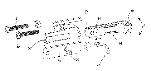
In as clearly shown in figure 1, the
wall cupboard holder 10 according to the invention com-
prises a hooking element 14 to a supporting element fixed
to the wall, said hook 14 is coupled at a first end 15'
to a central portion 16 of a plate element whereas at a
second end, which freely protrudes behind the central
portion 16, there is a hook-shaped fixing portion 15 to
the above support. In order to allow regulations, the
7
CA 02725517 2010-11-23
WO 2010/012504 PCT/EP2009/005628
connection of the hooking element 14 to the central por-
tion 16 is of the adjustable type in depth F and inclina-
tion A.
For this purpose, regulation means 17, 17' of the
depth F and inclination A of the hooking element 14 are
envisaged, said means 17, 17' are associated with and ac-
cessible in the front to the central portion 16.
According to the invention, the wall cupboard holder
as described above also comprises a side flange 18
10 which extends from the central portion 16, in which said
side flange 18 comprises fixing means 19 of the wall cup-
board holder group 10 to the internal side wall 12 of the
wall cupboard 11, in addition to the presence of at least
one element resistant to the shear forces 20, which are
generated when the wall cupboard holder 10 is assembled
and when the wall cupboard is loaded.
Said at least one element resistant to shear forces
protrudes from the side flange 18 on the side facing
the internal side wall 12 of the wall cupboard 11, and
20 collaborates with the previous fixing means 19 for a sta-
ble positioning of the wall cupboard holder 10 on an in-
ternal wall 12 of the wall cupboard 11.
As can be seen in figure 1, the regulation means 17,
17' of the depth F and inclination A of the hooking ele-
ment 14, which, as already mentioned, are associated with
8
CA 02725517 2010-11-23
WO 2010/012504 PCT/EP2009/005628
and accessible in the front to the central portion 16,
comprise two screw-female screw mechanisms.
In these mechanisms, there is a first regulation
screw 30 equipped with a head which is firmly
housed/entrapped in a counter-form 31' situated in the
first portion 16 and a threaded development which is lon-
gitudinally associated in an internal threaded seat of
the hooking element 14 in correspondence with the end 15'
opposite the hook 15.
Said first regulation screw 30 allows the longitu-
dinal movement (depth) of the hooking element 14 to be
regulated.
According to the invention, a second regulation
screw 31 is also envisaged, which is associated with the
first central portion 16 in a parallel and upper position
with respect to the first regulation screw 30.
Said second regulation screw 31 acts on a movable
circular lunette 33 situated at the opposite side with
respect to the head of the second regulation screw 31 and
can be moved, specifically due to the effect of the
second regulation screw 31, to enforce a rotation of the
hooking element 14 around a riveted pin 34.
According to an embodiment shown in figures 2-2c,
the elements resistant to shear forces 20 comprise at
least one plug element 20 protruding from the side flange
9
CA 02725517 2010-11-23
WO 2010/012504 PCT/EP2009/005628
18, which is coupled, not necessarily forcedly, with a
hole 41 situated in the internal side wall 12 of the wall
cupboard 11 (shoulder).
As shown in figure 2c, said plugs 20 collaborate
with the previous fixing means 19, for example screws,
for a stable positioning of the wall cupboard holder 10
on an internal side wall 12 of the wall cupboard 11, com-
pletely preventing the misalignment of the wall cupboard
holder 10 with respect to the relative wall cupboard 11.
In the above embodiment, the plug elements 20 can be
positioned directly on the side flange 18 during the pro-
duction of the wall cupboard holder 10, but alternatively
they can also be produced separately and subsequently
welded onto the side flange 18, as shown in the embodi-
ment of figures 4-4c.
The plug elements so far described are preferably
hollow cylindrical plugs with a circular section but, al-
ternatively, and in relation to the type of cupboard to
be coupled with the wall cupboard holder 10 and an esti-
mation of the load burdens, they can be hollow cylindric-
al plugs having a non-circular but circumferential arc
section as shown in the embodiments of figures 3-3c.
As already specified, the fixing means 19 can com-
prise at least one fixing screw 19 of the flange 18 to
the internal side wall 12 of the wall cupboard 11 in
CA 02725517 2010-11-23
WO 2010/012504 PCT/EP2009/005628
which said at least one fixing screw 19 can be coupled
with the relative side flange 18 in a different position
with respect to the at least one plug element 20 through
relative holes 44.
Alternatively, the above screws 19 can be coupled
with the side flange 18 inside the previous plug elements
20.
According to another embodiment, the wall cupboard
holder group 10 can comprise, as fixing means 19, at
least one expansion peg 21 equipped with gripping teeth
and which can be activated by screws 19, which (21), like
the screws 19 of the previous examples, fixes the side
flange 18 to the internal side wall 12 of the wall cup-
board 11.
Said pegs 21 can be coupled with the side flange 18
either in a different position with respect to the at
least one plug element 20, or, as shown in figures 5-5c,
coaxially to the at leapt one plug element 20.
Finally, according to a last embodiment, the fixing
means comprise at least one expansion peg 21 activated by
means of cursors 22 with shaped heads which 21, like the
previous pegs, fix the side flange 18 to the internal
side wall 12 of the wall cupboard 11.
These pegs 21 can also be coupled with the side
flange 18 either in a different position or coaxially to
11
CA 02725517 2010-11-23
WO 2010/012504 PCT/EP2009/005628
the at least one plug element 20, as shown in figures 6-
6c.
From the above description, and with reference to
the figures, it is evident how a visible wall cupboard
holder group for anchoring a wall cupboard to the wall
according to the invention is particularly useful and ad-
vantageous. The objective indicated in the preamble of
the invention has therefore been achieved.
The visible and adjustable wall cupboard holder 10
for the assembly of a wall cupboard to a wall according
to the present invention, in fact, ensures an easy and
firm assembly on any type of wall cupboard preventing any
possible misalignment of the wall cupboard holder 10 it-
self with respect to the relative cupboard also when the
latter is loaded.
This firm positioning can be obtained thanks to the
presence of the elements resistant to shear forces 20
protruding from the side flange 18 towards the internal
side wall 12 of the wall cupboard 11, wherein said ele-
ments resistant to shear forces 20, such as cylindrical
plugs, collaborate with the fixing means 19, such as
screws or expansion pegs possibly equipped with gripping
teeth, to ensure a stable positioning of the wall cup-
board holder group 10 on the internal wall 12 of the wall
cupboard 11.
12
CA 02725517 2010-11-23
WO 2010/012504 PCT/EP2009/005628
The forms of the visible wall cupboard holder group
for the fixing of a wall cupboard to a wall, of the
invention, as also the materials, can obviously differ
from those shown for purely illustrative and non-limiting
5 purposes in the drawings.
The protection scope of the invention is therefore
delimited by the enclosed claims.
15
25
13