Note: Descriptions are shown in the official language in which they were submitted.
CA 02725724 2010-12-20
1
DOUBLE-WALLED CUP
The present application is a division of Canadian patent application no.
2,621,453
corresponding to international laid-open patent application no. WO 2007/028623
filed
on September 7, 2006.
The invention as broadly disclosed hereinafter relates to a double-walled cup
with an
inner and outer wall, wherein at its upper end the cup has a cup opening and
at its
lower end a bottom part. At least the outer wall is essentially made from
paper,
cardboard or the like.
A double-walled cup of this nature is known from EP 1 227 043. With this
design the outer
wall is formed by a sleeve, which is generally pushed from below onto an inner
cup forming
the inner wall. The sleeve forming the outer wall is attached to the inner cup
at its upper end
and at its lower end, wherein an air gap is formed between the sleeve and the
inner cup,
which provides thermal insulation for the double-walled cup.
A double-walled cup of this nature exhibits good insulating properties, so
that it can be well
used both for storing and extracting a warm or hot drink and for storing and
extracting a
cooled drink or the like. The inner cup is similarly manufactured from paper,
cardboard or
the like, wherein at least the inner cup has in addition a fluid-tight coating
on its inner side.
The object of the present invention is to improve a double-walled cup of this
nature such
that it can be more rapidly and simply produced and assembled whilst
maintaining the
appropriate thermal insulation properties and at the same time the structure
of the double-
walled cup is realised in a more stable manner.
More specifically, the object of the present invention as claimed is a double-
walled
cup a double-walled cup with an inner and outer wall, an upper cup opening and
a
lower cup bottom, wherein at least the outer wall is essentially formed from
paper or
cardboard and wherein the inner wall is formed by an inner cup which is
inserted into
CA 02725724 2010-12-20
la
an outer cup providing the outer wall, said inner cup being detachably
attached in the
outer cup and being made of a plastic material that is at least fluid-tight,
characterised in that:
- the inner cup has an inner edge flange which at least partially surrounds
its upper
inner cup opening;
- the inner edge flange is formed as a radially outward protruding flat edge
flange;
and
- either the flat edge flange contacts a shoulder which protrudes from the
inner side
of the outer cup at least in places;
- or the flat edge flange is inserted with its free end into a groove which
extends
around the inner side of the outer cup.
According to the invention a double-walled cup of this nature is characterised
in particular in
that the inner cup providing the inner wall is inserted into an outer cup
providing the outer
wall and is attached to it in particular in a detachable manner and the inner
cup is formed at
least from a fluid-tight plastic material.
Through the use of an inner cup and an outer cup, the structure of the double-
walled cup is
more mechanically stable, because a sleeve open at the bottom is omitted,
which is pushed
onto the inner cup from below. If the inner cup has a leak, this does not lead
to a leak in the
double-walled cup by means of which a user's clothes may become dirty.
Instead, the outer
cup provides a catchment method for a leak of this nature in the inner cup, so
that the
double-walled cup according to the invention is not only more stable, but
rather is also safer
CA 02725724 2010-12-20
2
in use.
The inner cup can be arranged in the outer cup in various ways and can be
attached in it or
to it. Through the use of two cups many methods are available for the
detachable
attachment, such as for example in the region of the inner and outer walls, in
the region of
optionally available edges of both cups and / or also in the region of the
bottom parts of
both cups. In addition the manufacture of the inner cup is simplified, because
it is formed
from a plastic material and can be manufactured in various designs and
variations by
appropriate plastic moulding techniques and can then be simply inserted into
the outer cup.
This appropriate plastic material of the inner cup is at least fluid-tight, so
that with the use of
pourable or liquid content, the inner cup is adequately sealed.
In order to improve the protective capability of the outer cup in particular
with a leak of the
inner cup or with the passage of the foodstuff or the like contained in the
inner cup into the
outer cup and similarly design it at least fluid-tight, the outer cup can be
coated inside and /
or outside with a fluid-tight plastic film. This plastic film can, in
particular with the coating of
the outer cup on the outside, improve the printing capability of the outer
cup, wherein
already a relatively good printing capability is ensured by the use of paper,
cardboard or the
like for the outer cup.
In order to improve the removal in particular of a liquid foodstuff from the
double-walled cup,
the outer cup can have an outwardly protruding edge flange at least partially
surrounding an
appropriate upper outer cup opening. In this way the outer cup is not only
stabilised in its
shape in particular in the region of the outer cup opening, but rather also
drinking a liquid
foodstuff from the cup is simplified. In an advantageous embodiment the
corresponding
edge flange can be formed as a rolled rim which is beaded outwards. The
appropriate
plastic film can also be applied in the region of this rolled rim.
In order to also simplify the removal from the inner cup or optionally to
provide an upper
seal of the inner cup with respect to the outer cup, the inner cup can have at
least partially
an inner edge flange surrounding its upper inner cup opening. This can be
formed in
various ways depending on requirements.
In an advantageous embodiment the inner edge flange can at least in places
contact the
CA 02725724 2010-12-20
3
outer edge flange of the outer cup from above. In this way removal of the in
particular liquid
foodstuff from the double-walled cup is possible via both of the edge flanges
which are in
contact with one another. In addition a very simple and adequate sealing of
the inner cup
with respect to the outer cup is provided in the region of the edge flanges.
In order to improve the sealing and to already, for example, achieve a certain
attachment of
the inner cup with respect to the outer cup or at least a fixing in the
relative position, the
inner edge flange can at least partially circumferentially grip the outer edge
flange. The
circumferential gripping effect can be realised in various ways. In one
embodiment the outer
edge flange is relatively loosely gripped circumferentially by the inner edge
flange so that
the mutual support of the edge flanges essentially only serves the positioning
of the inner
cup in the outer cup. There is similarly the possibility that the
circumferential gripping occurs
relatively tightly so that essentially a frictionally engaged joint is
provided in this region
which already facilitates a certain and optionally also adequate fixing of the
inner cup in the
outer cup. In this connection, in order to improve the fixing, the inner edge
flange and the
outer edge flange can be joined together in particular detachably. A joint of
this nature can
be established by a suitable adhesive or also for example by fusing and
joining with the
plastic film applied to the outer cup in the region of the edge flanges.
Of course, in addition to a joint of this nature in the region of the edge
flanges, a further joint
by adhesive, fusing of the plastic film or the like can also occur in the
region of the inner and
outer walls of the inner and outer cups or in the region of the corresponding
bottom parts of
both cups additionally or also alternatively.
In particular when using a rolled rim circumferentially flanged outwards on
the outer cup it
may prove to be advantageous if the inner edge flange is formed with an
inverse U-shape
and with the inner cup inserted the rolled rim circumferentially grips from
above by means of
the corresponding U-limbs.
Then the corresponding detachable attachment of both cups can also occur by
means of
the U-limbs and the rolled rim. A frictionally engaged joint may be adequate
in this
connection.
There is also the possibility that the inner edge flange is formed essentially
as a flat edge
flange protruding radially outwards, which for example essentially only
contacts the outer
CA 02725724 2010-12-20
4
edge flange or the rolled rim from above. Here, there is the possibility that
a flat edge flange
of this nature protrudes radially over the outer edge flange and forms for
example a drip
edge in its free end.
In another embodiment of the invention the inner edge flange can be placed on
a shoulder
protruding at least in places from the inner side of the outer cup, in
particular when formed
as a flat edge flange. In this way the upper inner cup opening is arranged
offset downwards
with respect to the upper outer cup opening and the inner cup is completely
accommodated
by the outer cup. An appropriate attachment and / or sealing between the inner
cup and
outer cup can occur through the support of the inner cup flange on the
corresponding
shoulder, wherein in this region a detachable attachment can also occur via
adhesive,
fusing of plastic film or the like applied to the outer cup.
Instead of supporting the inner edge flange on a shoulder of this nature, with
a further
embodiment the inner edge flange which is in particular formed as a flat edge
flange can be
inserted with its free end in a groove running around the inner side of the
outer cup. Both by
supporting on the shoulder and also by insertion into the groove, the
corresponding relative
position of the inner cup is defined in relation to the outer cup. The
engagement of the free
end in the groove can in particular provide a positively locked joint of both
cups, wherein a
certain latching effect is established by the engagement of the free end in
the groove on
inserting the inner cup into the outer cup. Also in this connection the
appropriate attachment
or sealing can occur in the region of the free end and the groove, with in
turn adhesive,
fusing of the plastic film on the outer cup or the like.
The insertion of the inner cup using a shoulder or a groove is at least with
the use of the
groove thus simplified in that it has a depth which is less than the length of
the flat edge
flange. This can however similarly apply in the region of the shoulder so that
also its depth
is less than the length of the flat edge flange. In this way manufacture of
the appropriate
shoulder or groove is simplified, because it can be formed in the outer cup
with little
expense and without significantly affecting its outer visible side.
In particular with the formation of a groove, the insertion of the free end of
the flat edge
flange and sealing in this region can be improved in this way if optionally
the flat edge
flange is rounded off at its free end.
CA 02725724 2010-12-20
There is the possibility that the outer cup is conically extended upwards at
its upper end in
an appropriate upper wall section between the outer cup opening and the
shoulder. In this
way the arrangement of the inner cup and in particular of the flat edge flange
with the
shoulder is simplified. However, in this connection to improve the fixing of
the inner cup in
the outer cup, the corresponding wall section of the outer cup can extend from
the shoulder
upwards essentially vertically to the corresponding outer edge flange.
In a further embodiment according to the invention the inner cup can end with
its lower end
or bottom part spaced to the lower end or bottom part of the outer cup with
the formation of
an accommodation space between these ends or bottom parts. This accommodation
space
can be used to accommodate a surprise present or the like, which is accessible
in particular
after emptying the inner cup and its removal from the outer cup. There is
however also the
possibility that the lower end or the bottom part of the inner cup is in
contact with the lower
end or bottom part of the outer cup, so that the inner cup is not just
supported by contact
with the corresponding edge flanges, but rather also through contact with the
corresponding
bottom parts in the outer cup. In addition in this connection, attachment of
both cups can
occur also in the region of the bottom parts or lower ends. With an
accommodation space of
only small size it may also provide thermal insulation, because direct contact
in this region
between the inner cup and outer cup is avoided.
The thermal insulation between the inner and outer cups can be improved in
that between
at least the inner cup wall and the outer cup wall an air chamber is formed in
particular
running in the circumferential direction. There is also the possibility that a
large number of
air chambers of this nature can be arranged in the circumferential direction,
which are
interrupted by appropriate supporting ribs, supporting protrusions or the like
between both
cups. The corresponding air chambers can in this connection both extend in the
vertical
direction and be separated from one another in the circumferential direction
and / or extend
in the circumferential direction and be separated from one another in the
vertical direction.
For the cross-sections of the cups various geometrical shapes are conceivable,
such as
circular, oval, rectangular and in particular square. In order to simplify
holding the double-
walled cup, the inner cup wall and the outer cup wall can extend upwards
conically. Various
relationships are possible for the appropriate cone angle for the inner cup
wall and outer
cup wall. Direct contact between the inner and outer walls is for example then
possible
when the cone angle of the inner cup wall and the outer cup wall are equal.
However, for an
CA 02725724 2010-12-20
6
equal cone angle a constant spacing between the inner and outer walls can also
be present
if for example the arrangement of the inner cup in the outer cup occurs using
the shoulder
or the groove. Similarly there is the possibility that the cone angle of the
inner cup wall and
the outer cup wall are different. In one embodiment the cone angle of the
outer cup wall is
larger than the cone angle of the inner cup wall so that a spacing between the
inner and
outer cup walls increases in the direction of the cup opening. Also the
inverse case is
possible, i.e. a cone angle of the inner cup wall is larger than a cone angle
of the outer cup
wall so that the spacing between both increases in the direction of the bottom
of the cup.
It has already been pointed out that the appropriate attachment of the two
cups can take
place at different points. If this attachment is for example to also occur in
the region of the
cup walls, it may be regarded as advantageous if the inner cup wall contacts
the outer cup
wall inside at least in places.
The appropriate plastic material of the inner cup not only improves its
sealing properties,
but also its service life. In addition, a plastic material of this nature can
also be formed gas
tight in a simple manner or it in any case features appropriate sealing with
respect to gas as
well as with respect to liquid. In this way sensitive foodstuffs, such as
yoghurt, biscuit, or the
like are better protected against odours or other gases. In a similar way an
emission of an
odour or a gas from the double-walled cup is prevented if it contains for
example cheese or
another strongly smelling foodstuff.
Closure of the double-walled cup can be achieved in various ways. For example
a lid can
be placed in a known manner on the corresponding edge flange of the outer cup
or inner
cup. There is also the possibility of detachably attaching a sealing foil for
closing the inner
cup to the inner or outer edge flange.
In principle there is also the possibility that the inner cup has a different
geometrical shape
than the outer cup apart optionally from the region of the edge flanges that
are in contact
with one another or in the region where the inner edge flange is arranged on
the shoulder or
in the groove. Thus an oval or rectangular inner cup can also be arranged for
example in an
outer cup with a round cross-section or vice versa. The appropriate
positioning of the cups
relative to one another or also their attachment can then only occur in the
region of the
geometrical similar edge flanges or by contact of the inner edge flange on the
shoulder or in
the groove.
CA 02725724 2010-12-20
7
For reasons of a simplified arrangement of the two cups it may however be
advantageous if
the cross-sections of the inner and outer cups are essentially geometrically
similar to one
another over the complete height of the double-walled cup.
Referring to the above description, it may also be of advantage if the inner
cup stands at
least in places on a bottom part of the outer cup at its lower end. In this
way the positioning
of the inner cup is supported in the outer cup and furthermore in the region
of this support a
detachable attachment of both cups can also occur. If the support is only
provided in
places, the remaining region can also provide thermal insulation.
It is also pointed out that thermal insulation with the double-walled cup
according to the
invention also can only occur through the outer cup formed out of paper,
cardboard or the
like, even if in particular the inner cup wall is in contact with the outer
cup wall from the
inside. There is here the possibility that the outer cup has a sufficient
material thickness in
the region of its outer cup wall or it is formed for example double-walled
with optionally air
chambers arranged between the walls.
A plastic material for the inner cup which is both fluid and also gas-tight is
for example
polypropylene, polystyrene, polyester, polyethylene, a combination of these
materials or the
like.
It has already been pointed out that the connection between the inner and
outer walls can
occur in various ways, wherein in particular a connection by means of the
plastic film
applied to the outer cup can be provided by polyethylene.
In connection with the accommodation space mentioned above for accommodating a
surprise present it may furthermore prove to be advantageous if it can also be
removed
already before the emptying of the inner cup and without releasing the inner
cup from the
outer cup. This can be realised for example in that a lower cup section of the
outer cup is
detachable from the upper cup section.
A possibility of providing a detachable capability of this nature between the
cup sections is
through the formation of a tear-off strip or tear-off line between these cup
sections.
CA 02725724 2010-12-20
8
The tearing off of the strip or line can be simplified if a tear-off tab
protrudes or at least a
tear-off tab of this nature is joined to the strip or line and for example can
be folded out of
the outer surface of the outer cup.
Advantageous embodiments of the invention are given in the figures included in
the
drawings. The following are shown:
Fig. 1 a longitudinal section through a first embodiment of a double-walled
cup;
Fig. 2 an enlarged illustration of a detail "A" of Figure 1;
Fig. 3 an illustration analogous to Figure 2 for a further embodiment;
Fig. 4 an illustration analogous to Figure 2 for another further embodiment;
Fig. 5 a longitudinal section through a second embodiment of a double-walled
cup
according to the invention;
Fig. 6 a longitudinal section through a third embodiment of a double-walled
cup
according to the invention;
Fig. 7 a longitudinal section through a fourth embodiment of a double-walled
cup
according to the invention;
Fig. 8 an enlarged illustration of a detail "A" of Figure 7;
Fig. 9 a longitudinal section through a fifth embodiment of a double-walled
cup
according to the invention; and
Fig. 10 an enlarged illustration of a detail "A" of Figure 9.
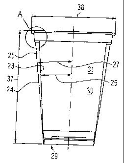
Fig. 1 shows a longitudinal section through a first embodiment of a double-
walled cup 1 with
an inner cup 2 and an outer cup 3. The inner cup 2 is arranged spaced with its
lower end 20
to the lower end 21 of the outer cup 3, wherein this lower end 21 is formed by
a bottom part
29. Between the ends 20, 21 an accommodation space 22 is formed which also
serves as
CA 02725724 2010-12-20
9
an air chamber 25 for the thermal insulation between the two cups 2, 3. A
surprise present
40 is arranged within the accommodation space 22. Access to the accommodation
space
22 is obtained by tearing off a tear-off strip 34 which is formed between an
upper cup
section 33 and a lower cup section 32 of the outer cup 3. The tear-off strip
34 has a tear-off
tab 35 which can be grasped for tearing off.
The inner and outer cups 2, 3 each have at the upper end an appropriate upper
inner or
outer cup opening 8, 6. This is closed off in Fig. 1 by a sealed-on sealing
foil 28. The
sealing foil 28 is sealed on in the region of an inner edge flange 9. This
inner edge flange 9
protrudes outwards from the inner cup 2 and surrounds the corresponding inner
cup
opening. On the inside 31 of the inner cup 2 a consumable foodstuff can be
arranged and
after removal of the sealing foil 28 or also of a corresponding lid it can be
removed from the
double-walled cup 1.
Below the corresponding inner edge flange 9 an outer edge flange 5 is arranged
in the form
of a rolled rim 7 which is beaded outwards. This outer edge flange 5 is
arranged on the
upper end of the outer cup 3 and surrounds its upper outer cup opening 6.
Accordingly in Fig. 1, the inner wall or inner cup wall 23 formed by the inner
cup 2, refer
also to the following embodiments, and the outer wall or outer cup wall 24
formed by the
outer cup 3, refer also to the following embodiments, are in contact, wherein
no air chamber
is formed between them and the thermal insulation is achieved through the
outer cup 3 and
its material, such as paper, cardboard or the like.
The inner and outer cups 2, 3 are conically extended in the direction of the
respective cup
opening, wherein the corresponding cone angles, refer also to the following
embodiments,
are equal in this case.
In the following figures 2 to 4 various embodiments for detail "A" according
to Fig. 1 are
illustrated enlarged. In these figures as with all other figures the same
parts are in each
case identified with the same reference numerals and are sometimes only
mentioned in
conjunction with a figure.
In Fig. 2 it can be seen that the sealing foil 28 is applied from above onto a
flat region of the
inner edge flange 9 where it is attached sealed. The inner edge flange 9 has
an inverse U-
CA 02725724 2010-12-20
shape with two U-limbs 10 and 11 pointing downwards. These overlap the outer
edge
flange 5 from above which is formed as the rolled rim 7. Here, the outer U-
limb 10 is
spaced, forming a free space, relative to the outer side of the rolled rim 7.
The inner U-limb
11 and the connection of the U-limbs are in each case in contact with the
rolled rim 7 or the
outer cup wall 24.
In the embodiment of Fig. 3 the respective U-limbs 10, 11 are in close contact
with the
rolled rim 7 so that essentially a frictionally engaged joint is formed
through the contact of
the outer edge flange 5 and the inner edge flange 9.
This applies analogously also to the embodiment of Fig. 4, wherein it has two
U-limbs of
approximately equal material strength, whereas in the embodiment according to
Fig. 3 the
outer U-limb 10 has a greater material thickness than the inner U-limb 11. In
both
embodiments according to Figs. 3 and 4 the connection of the U-limbs 10 and 11
is in each
case formed with a greater material thickness than the U-limbs.
In Fig. 5 a second embodiment of a double-walled cup is illustrated. This
differs from the
embodiment according to Fig. 1 essentially in that the inner cup 2 extends
with its lower end
to the lower end 21 of the outer cup 3. The lower end 20 of the inner cup 2 is
thus so
formed that the inner cup 2 in some places stands on the corresponding bottom
part 29 and
an air chamber 25 is formed between them.
The corresponding cone angles 26 of inner cup 2 and 27 of outer cup 3 are each
equally
large, wherein between the inner cup wall 23 and outer cup wall 24 no further
free space is
formed for an air chamber or the like, but rather both cup walls are in
contact over their
complete height.
In the third embodiment according to Fig. 6 the cup walls 23, 24 are arranged
spaced from
one another at least over the greatest part of their longitudinal extent,
wherein an air
chamber 25 of essentially equal width is formed due to the equal cone angles
26, 27 in the
direction perpendicular to the verticals 36.
The other features of the third embodiment essentially correspond to those of
the first and
second embodiments according to Figs. 1 and 5.
CA 02725724 2010-12-20
11
It should be noted that the respective details "A" corresponding to the Figs.
2 to 4 can be
formed for all embodiments described so far.
The attachment of the two cups 2, 3 can on one hand occur in the region of the
corresponding edge flange 5, 9. This can for example be realised in that,
refer to Figs. 3
and 4, a frictionally engaged joint is formed between the edge flanges.
Additionally or
alternatively, an adhesive can be arranged between the edge flanges or also
between the
inner cup wall 23 and the outer cup wall 24 or between the lower end 20 of the
inner cup 2
and the lower end 21 of the outer cup 3 or for the detachable connection of
both cups 2, 3 a
plastic film 4, refer to Fig. 1, applied to the inner side and optionally also
to the outer side of
the outer cup 3 can be briefly melted and then joined to the inner cup 2 at
the appropriate
point. The joint via the plastic film can of course also occur in the region
of the
corresponding edge flange 5, 9.
There is similarly the possibility that the cone angles 26, 27 in the
embodiments according
to Figs. 1, 5 and 6 are different, refer for example also to the fifth and
sixth embodiments
according to Figs. 7 and 9. Here, the cone angle 26 of the inner cup can be
smaller than the
corresponding cone angle 27 of the outer cup or also vice versa. Due to
different cone
angles a corresponding air chamber 25 is also produced between the inner cup
wall 23 and
the outer cup wall 24, refer again to Figs. 7 and 9.
The fourth embodiment according to Fig. 7 differs from the embodiments due to
a different
positioning and formation of the inner edge flange 9. This is formed as the
flat edge flange
12, refer also to Fig. 8, which is an enlarged illustration of the detail "A"
from Fig. 7. This flat
edge flange 12 lies with its underside and its free end 15 on a shoulder 14
which is formed
on an inner side 13 of the outer cup 3. Above the shoulder 14 a wall section
19 of the outer
cup wall 24 extends over a height 39. This wall section 19 extends essentially
parallel to the
verticals 36 up to the rolled rim 7 as the outer edge flange 5. A
corresponding depth 17 of
the shoulder 14 is less than a length 18 of the flat edge flange 12, with
which it is spaced
radially outwards from the inner cup 2 in the region of the inner cup opening
8. In this way
an appropriate air chamber 25 is formed between the inner cup wall 23 and the
outer cup
wall 24, refer also to Fig. 7, which due to the different cone angles 26, 27
is formed with a
width reducing in the direction of the bottom part 29 of the outer cup 3.
For the fourth embodiment according to Fig. 7 as well as for the other
embodiments, the
CA 02725724 2010-12-20
12
inner cup 2 can also be formed according to Fig. 1, i.e. spaced to the bottom
part 29 of the
outer cup 3. Furthermore, with this embodiment as well as with the other
embodiments
there is the possibility that an appropriate shoulder is formed on the inner
side of the inner
cup 2, which for example, with double-walled cups 1 inserted into one another
serves as a
destacking aid, wherein a shoulder of this nature prevents the stacking depth
of cups of this
nature being too large, leading to jamming of the cups with one another.
Also in the embodiments according to Figs. 5, 6, 7 and 9 there is the
possibility of arranging
an appropriate surprise present 40 in the accommodation space 22, when the
inner cup 2
terminates sufficiently spaced to the bottom part 29 of the outer cup 3.
There is similarly the possibility that for example in the embodiment
according to Fig. 7 the
depth 17 of the shoulder 14 essentially matches the length 18 of the flat edge
flange 12 and
the air chamber 25 is formed such that the cone angle 26 of the inner cup 2 is
larger than
the cone angle 27 of the outer cup 3. In this way an air chamber 25 is formed
which has an
increase in width in the direction of the bottom part 29.
In the embodiments according to Figs. 7 and 9, the inner cup 2 is in each case
completely
positioned in the inside 30 of the outer cup 3, whereas in the embodiments
according to
Figs. 1, 5 and 6 it protrudes at least with its inner edge flange 9 from the
inside 30 of the
outer cup 3.
In the fifth embodiment according to Fig. 9 the flat edge flange 12 is fixed
as the inner edge
flange 9 of the inner cup 2 in a different place and manner to the outer cup
3. Here, the
outer cup 3 has a groove 16 on its inner side 13 spaced to the rolled rim 7,
in which the free
end 15 of the flat edge flange 12 is inserted. This free end 15 can here be
formed rounded
off for improved fitting and accommodation with respect to the groove 16.
The remaining features of the fifth embodiment correspond to the fourth
embodiment
according to Fig. 7. Appropriate alternatives of the embodiments are in turn
possible, refer
for example to the different cone angles 26, 27 or the spaced end of the inner
cup 2 with
respect to the bottom part 29 of the outer cup 3. Also the relation of the
cone angles 26, 27
can be inverted, i.e. the cone angle 26 of the inner cup can be larger than
the cone angle
27 of the outer cup 3.
CA 02725724 2010-12-20
13
Also in the embodiment according to Figs. 9 and 10 a corresponding depth of
the groove 16
is lower than a length 18 of the flat edge flange 12. There is however
similarly the possibility
that the depth essentially corresponds to the length so that in the region of
the groove 16
the corresponding cup walls 23 and 24 are in contact and a corresponding air
chamber 25
is formed with increasing width in the direction of the bottom part 29.
In Figs. 7 and 9 the total height 37 of the double-walled cup 1 is still
provided, which here is
determined by the height of the outer cup 3. In Figs. 1, 5 and 6 approximately
the thickness
of the joint of the two U-limbs 10, 11, refer to Figs. 2 to 4, is added in
each case to the total
height of the outer cup 3 in order to obtain the total height 37 of the double-
walled cup 1.
The corresponding diameter 38 of the cup opening is in the embodiment
according to Figs.
7 and 9 determined by the diameter 38 of the outer cup 3, wherein this is
determined in
Figs. 1, 5 and 6 by the corresponding diameter of the inner cup 2 in this
region.
It should be noted that other methods for the outer and inner edge flanges are
possible.
One possibility is for example that the inner edge flange 9 is formed as an
outwardly
beaded rolled rim, which engages from above into a U-shaped outer edge flange
5 open at
the top. Similarly there is the possibility that instead of a flat edge flange
12 in Fig. 10 a
rolled rim is formed as the inner edge flange 9, which correspondingly engages
the groove
16.
Other variations and combinations of the various embodiments according to the
invention
are possible, such as for example also a further shoulder in the outer cup 3,
on which the
lower end 20 of the inner cup 2 is supported.
The inner cup is formed from a gas and fluid-tight plastic material such as
polypropylene,
polystyrene, polyester, polyethylene or a combination of these materials and
can be
produced according to appropriate plastic moulding techniques in a simple and
rapid
manner. Through the use of a material of this nature the inner cup is also
sufficiently strong
and has an adequately long service life.
Through the use of paper, cardboard or the like for the outer cup it can be
easily printed on
its outer side, wherein this printing capability can be improved further by a
plastic film of, for
example, polyethylene applied appropriately to the outer side.