Note: Descriptions are shown in the official language in which they were submitted.
CA 02725951 2015-06-15
SPECIFICATION
TITLE: IN-BUILDING STORAGE APPARATUS AND METHOD OF TAKING
ARTICLE OUT OF THE SAME
FIELD OF THE INVENTION
[0001]
The present invention relates to an in-building storage apparatus and a
method of taking an article or articles out of the same, both of which make it
possible to store articles in a storage space such as an attic and an
underfloor.
BACKGROUND ART
[0002]
Since a room can have a limited space therein, there has been made an
attempt in which an underfloor storage unit including a storage container is
installed in an opening space below a floor equipped with a cover for opening
and
closing the opening space and for putting articles into the opening space
therethrough or taking articles out of the opening space therethrough, in
order to
effectively make use of a dead space. However, since the underfloor storage
unit
is designed to merely have a storage container, a storage volume is limited to
a
volume capable of being stored in the storage container. Thus, there has been
developed an in-building storage apparatus capable of increasing a storage
volume by designing a plurality of storage containers to be selectively taken
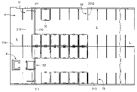
out.
Such an in-building storage appratus has been suggested in the patent
references
1 to 3, for instance.
[0003i
The underfloor storage apparatus suggested in the patent reference 1
comprises two rails formed in an underfloor space and extending in parallel
with
each other, a floor being partially open, a plurality of frames each having
rollers so
1
CA 02725951 2015-06-15
as to be able to move along the two rails independently of one another, a
plurality
of storage containers suspended on each of the frames, and a storage container
mounted on an elevator.
[0004]
The underfloor storage unit suggested in the patent reference 2
comprises rails extending to cover a position situated below a floor opening
which
is caused to be open or closed by means of a cover, a carriage designed to be
able to
controllably run on the rails, and include an elevator which can be controlled
to
move upwardly and downwardly, a storage case formed with a flange to be
suspended, and L-shaped hanger pairs arranged at a suspending interval at a
terminating end of a travelling path of the carriage, remote from the floor
opening.
[0005]
In the in-building storage unit suggested in the patent reference 3,
when an article lying on a floor is stored into the unit, a container or an
article is
lowered through an entrance/exit onto a receiver unit of a carriage, and the
carriage is driven to run in a path section. When the container reaches a
target
empty receiver, the receiver unit is operated for delivering the container to
the
empty receiver.
PRIOR ART REFERENCES
PATENT REFERENCES
[00061
Patent reference 1: Japan Utility Model Application Publication No. 56-176335
Patent reference 2: Japan Patent Application Publication No. 60-215974
Patent reference 3: Japan Patent Application Publication No. 7-48924
DISCLOSURE OF THE INVENTION
PROBLEMS TO BE SOLVED BY THE INVENTION
2
CA 02725951 2015-06-15
[0007]
However, it is necessary for the underfloor storage apparatus suggested
in the patent reference 1 to have a gap between the storage container rows
suspended from the rails for taking a storage container lying on the elevator.
For
instance, in the case that a lot of storage containers are suspended from the
rails,
all of the storage containers suspended from the rails is subsequentially
moved by
holding a suspended storage container situated above the elevator and pushing
the adjacent storage container. Consequently, if a lot of storage containers
were
suspended from the rails, since it is necessary to simultaneously move the
storage
containers, it would be a hard work for powerless workers.
[0008]
In accordance with the underfloor storage unit suggested in the patent
reference 2, it is able to increase a storage volume by designing the rails to
be
cross-shaped, circular or grid-shaped. However, if the rails were designed to
be
cross-shaped, the carriage has to perpendicularly turn at a corner. The patent
reference 2 does not refer to a mechanism for the carriage to perpendicularly
turn
at a corner. In order for wheels driven by a motor to be able to
perpendicularly
turn at a corner, the carriage has to have a complex mechanism, but it is not
easy.
[0009]
In the in-building storage unit suggested in the patent reference 3, the
carriage runs at a U-shaped path with all corners in straight angles formed
between fixed storage shelves facing each other, in order to reach a target
storage
container. Accordingly, the carriage has to perpendicularly turn at a corner
of a
path, similarly to the carriage suggested in the patent reference 2. Thus,
wheels
of the carriage might be complex in structure.
In order for the driven wheels to have a relatively simple structure, it
would be necessary to design the wheels not to perpendicularly turn, but to
arcuately turn, however, in which case, it would be necessary to have a broad
space for pathes.
3
CA 02725951 2015-06-15
[0010]
In view of the above-mentioned problems, it is an object of the present
invention to provide an in-building storage apparatus and a method of taking
an
article or articles out of the same, both of which makes it possible to
readily bring
articles into or take articles out of the in-building storage apparatus, even
if a lot
of articles were stored in the same, and further, for a platform car which
carries
articles to be able to move in any directions by virture of a simple
structure.
SOLUTION TO THE PROBLEMS
[0011]
The in-building storage apparatus in accordance with the present
invention includes a guide rail mounted in a storage space in which articles
are to
be stored, and making sliding movement in a direction perpendicular to a
direction in which main rails extend, a platform car including a travelling
section
through which the platform car runs on the guide rail, and a lifting/lowering
section which lifts or lowers an article, suspenders each of which suspends an
article at such a height that the platform car can pass below articles held by
the
suspenders at a storage position, and a control unit having functions of
causing
the guide rail to slide, causing the platform car to move along the guide
rail,
causing the lifting/lowering section to lift or lower for taking a target
article out of
the suspenders, and causing a target article to be suspended by the
suspenders.
[00121
In the in-building storage apparatus in accordance with the present
invention, the suspenders suspend and thus store articles in a storage space.
The suspenders are designed to suspend articles at such a height that the
platform car can pass below articles, and hence, articles can be stored. Even
if
paths along which the platform car travels were designed to include paths
extending in a direction in which the guide rail slides, and paths extending
in a
direction perpendicular to the direction in which the guide rail slides, the
platform
4
CA 02725951 2015-06-15
car can perpendicularly turn at a corner by virtue of the operation of the
control
unit in which the control unit causes the guide rail to slide, and then, move
the
platform car along the guide rail. That is, since the guide rail and the
platform
car both make only linear movement, it is possible for the guide rail and the
platform car to have a simple structure.
Furthermore, since the control unit causes the guide rail to slide and
simultaneously the platform car to move along the guide rail when the platform
car is directed to a target article, it is possible for the platform car with
no articles
loaded thereon to move to a target article, passing below articles already
stored in
the suspenders. That is, the platform car is able to move to a target position
at
which a target article is stored from an initial position, passing below
articles
without making a long detour regardless of how much articles are stored.
Accordingly, it is not necessary for a user to work, because the platform car
takes
a target article among a lot of articles stored, and further, the platform car
is able
to move to and take out a target article at a short distance.
[0013]
It is preferable that the control unit has a function of causing the
platform car to linearly move to a target position from an initial position by
causing the platform car to move while the guide rail is caused to slide.
Since the
platform car can move to a target position at a minimum distance by linearly
moving to the target position from an initial position, it would be possible
to take
out a target article in a minimum period of time.
[0014]
It is preferable that the suspenders are arranged in a plurality of rows
to define paths on which the platform car can travel between adjacent rows of
the
suspenders with an article being mounted on the lifting/lowering section.
By designing the suspenders to be arranged in a plurality of rows to
define paths on which the platform car can travel with an article being
mounted
on the lifting/lowering section, when a target article is taken out, the
platform car
5
CA 02725951 2015-06-15
can diagonally travels to a target article below the rows of articles, load a
suspended article thereon, and travels on the paths to an exit.
[0015]
It is preferable that each of the suspenders includes a pair of vertical
sections spaced away from each other by a space longer than a maximum width of
an article, and holding sections each formed with each of the vertical
sections, and
inwardly extending to be spaced away from each other by a space shorter than
the
maximum width of an article for holding the article therewith.
When the platform car suspends an article on the suspenders, the
lifting/lowering section on which an article is loaded is elevated into a pair
of the
vertical sections. Then, the lifting/lowering section is lowered to thereby
cause
an article to be held by the holding sections. In this way, an article can be
suspended on the suspenders.
[0016]
It is perferable that the in-building storage apparatus further includes
a lift unit includes a pair of horizontal sections spaced away from each other
by a
space to allow an article mounted on the platform car to travel thereinto, for
holding the article thereon, and a lift section for lifting and lowering the
horizontal sections to carry an article to an entrance/exit.
By designing the in-building storage apparatus to further include the
lift unit, an article can be readily taken out of an exit.
[0017]
It is perferable that the in-building storage apparatus further includes
a second guide rail which slides relative to the guide rail to form a line
with the
guide rail, wherein the control unit causes at least one of the guide rail and
the
second guide rail to slide to allow the platform car to run between the guide
rail
and the second guide rail arranged to form a line.
It is possible to bring articles into or take articles out of a storage space,
even it is broad, by designing the control unit to cause one or both of the
guide rail
6
CA 02725951 2015-06-15
and the second guide rail to slide to allow the platform car to run between
the
guide rail and the second guide rail arranged to form a line.
[0018]
It is preferable that the in-building storage apparatus further includes
a relay rail to connect the guide rail and the second guide rail both making a
sliding movement to each other to define a linear rail to allow the platform
car to
run thereon. Even if a storage space were broad, and hence, it were necessary
to
stand pillars to support a ceiling of the storage space, it would be possible
to stand
pillars without interfering with sliding of the guide rail, by arranging the
relay
rail between the guide rails to allow the platform car to run thereon.
[0019]
It is preferable that the control unit has a function of causing at least
three guide rails, arranged such that they make a sliding movement in parallel
with one another, to make a sliding movement to form a line, and causing the
platform car to travel from a guide rail disposed at an end to a guide rail
disposed
at the other end. The control unit arranges the guide rails in a line, when
the
platform car used in the in-building storage apparatus in accordance with the
present invention is caused to move to a guide rail situated at one end to a
guide
rail situated at the other end. By so arranging the guide rails, the platform
car is
able to run to the other end from one end without decelerating or stopping for
transferring to a guide rail from another guide rail.
[0020]
The method of taking an article out of an in-building storage apparatus
including a guide rail, a platform car, and suspenders, in accordance with the
present invention, wherein each of the suspenders suspends an article at such
a
height that the platform car for carrying an article can pass below articles,
the
guide rail is disposed below a storage space in which the suspenders are
disposed,
and slide in a direction perpendicular to a direction in which main rails
extend,
the platform car includes a travelling section through which the platform car
runs
7
CA 02725951 2015-06-15
on the guide rail, and a lifting/lowering section which lifts or lowers an
article,
includes the steps of causing the platform car to pass below other articles to
move
from an initial position to a target position, that is, a position situated
below a
target article by moving the platform to a position situated below the target
article while the guide rail is being moved to a position situated below the
target
article, lifting the platform car for taking the target article out of the
suspenders,
and moving the platform car and causing the guide rail to make a sliding
movement for causing the platform car to leave the suspenders out of which the
target article was taken and further for heading the platform car to an exit.
[0021]
The method of taking an article out of an in-building storage apparatus,
in accordance with the present invention, makes it possible for the platform
car to
move below articles to a target position at which a target article is stored
from an
initial position without making a long detour regardless of how much articles
are
stored. Accordingly, it is not necessary for a user to work, because the
platform
car takes a target article among a lot of articles stored, and further, the
platform
car is able to move to and take out a target article at a short distance.
[0022]
It is preferable that the platform car is caused to linearly move to a
target position from an initial position. Since the platform car is able to
move to
a target position at a minimum distance by linearly moving to the target
position
from an initial position, it would be possible to take out a target article in
a
minimum period of time.
ADVANTAGES PROVIDED BY THE INVENTION
[0023]
The present invention makes it not necessary for a user to work,
because the platform car takes a target article among a lot of articles
stored, and
further, makes it possible for the platform car to move to and take out a
target
8
CA 02725951 2015-06-15
article at a short distance, ensuring that it is possible to readily bring
articles into
or take articles out of the in-building storage apparatus, even if the in-
building
storage apparatus stores a lot of articles therein. In addition, in the
present
invention, since the guide rail and the platform car both make only linear
movement, it is possible for the guide rail and the platform car to have a
simple
structure.
BRIEF DESCRIPTION OF THE DRAWINGS
[0024]
[FIG. 1] FIG. 1 is a cross-sectional view of the in-building storage
apparatus in accordance with the first embodiment of the present invention.
[FIG. 21 FIG. 2 is a plan view of the underfloor storage apparatus
which is a part of the in-building storage apparatus illustrated in FIG. 1.
[FIG. 31 FIG. 3 illustrates the guide rail and the platform car.
[FIG. 41 FIG. 4 is a side view of the platform car.
[FIG. 51 FIG. 5 is a plan view of the platform car.
[FIG. 6A] FIG. 6A is a perspective view of the suspenders.
[FIG. 6B] FIG. 6B shows a positional relation between the suspenders
and the platform car.
[FIG. 71 FIG. 7 is a perspective view of the storage container.
[FIG. 8] FIG. 8 is a perspective view of the lift unit.
[FIG. 91 FIG. 9 illustrates a mechanism for driving the lift unit.
[FIG. 101 FIG. 10 is a perspective view of a stage of the lift unit.
[FIG. 11] FIG. 11 is a block diagram of the control unit.
[FIG. 12] FIG. 12 is a block diagram of the personal computer and the
controller.
[FIG. 13] FIG. 13 is a drawing used for explaining movement pathes
along which the platform car travels.
[FIG. 141 FIG. 14 is a drawing used for explaining the operation of the
9
CA 02725951 2015-06-15
lifting/lowering section of the platform car.
[FIG. 15] FIG. 15 is a plan view of the in-building storage apparatus
in accordance with the second embodiment of the present invention.
[FIG. 16] FIG. 16 is a partially enlarged view of the guide rail and the
relay rail.
[FIG. 171 FIG. 17 is a front view of the guide rail.
[FIG. 18] FIG. 18 is a partially enlarged view of the guide rail and the
relay rail.
[FIG. 19] FIG. 19 is a block diagram of the control unit.
[FIG. 201 FIG. 20 is a drawing used for explaining routes along which
the guide rail is moved.
[FIG. 21] FIG. 21 is a vertical cross-sectional view of the in-building
storage apparatus in accordance with the third embodiment of the present
invention.
[FIG. 22] FIG. 22 is a horizontal cross-sectional view of a first story of
the in-building storage apparatus illustrated in FIG. 21.
[FIG. 231 FIG. 23 is a perspective view of the unit for bringing an
automobile into or taking an automobile out of a storage space.
[FIG. 241 FIG. 24 is a perspective view of a part of the platform car
and the guide rail.
[FIG. 251 FIG. 25 is a side view of the platform car.
[FIG. 26] FIG. 26 is a perspective view of the lift unit.
[FIG. 27] FIG. 27 is a block diagram of the control unit.
[FIG. 281 FIG. 28 is a horizontal cross-sectional view of a second story
of the in-building storage apparatus illustrated in FIG. 21.
CA 02725951 2015-06-15
EMBODIMENTS FOR REDUCING THE INVENTION TO PRACTICE
[0025]
(First Embodiment)
The in-building storage apparatus in accordance with the first
embodiment is explained hereinbelow with reference to the drawings. Firsts, a
structure of the in-building storage apparatus is explained with reference to
FIGs.
1 to 12. FIG. 1 is a cross-sectional view of the in-building storage apparatus
in
accordance with the first embodiment of the present invention. FIG. 2 is a
plan
view of the underfloor storage apparatus which is a part of the in-building
storage
apparatus illustrated in FIG. 1. FIG. 3 illustrates the guide rail and the
platform car. FIG. 4 is a side view of the platform car. FIG. 5 is a plan view
of
the platform car. FIG. 6A is a perspective view of the suspenders. FIG. 6B
shows a positional relation between the suspenders and the platform car. FIG.
7
is a perspective view of the storage container. FIG. 8 is a perspective view
of the
lift unit. FIG. 9 illustrates a mechanism for driving the lift unit. FIG. 10
is a
perspective view of a stage of the lift unit. FIG. 11 is a block diagram of
the
control unit. FIG. 12 is a block diagram of the personal computer and the
controller.
[0026]
As illustrated in FIGs. 1 and 2, the in-building storage apparatus 1 in
accordance with the first embodiment brings articles 10 into and take articles
10
out of an attic X and/or an underfloor Y both acting as a storage space, and
moves
the articles 10 between the attic X and the underfloor Y. The in-building
storage
apparatus 1 includes an attic storage unit 2 formed in the attic X, an
underfloor
storage unit 2 formed in the underfloor Y, a lift unit 4 moving the articles
10
between the attic storage unit 2 and the underfloor storage unit 3, and a
control
unit 5 controlling the attic storage unit 2, the underfloor storage unit 3,
and the
lift unit 4. The attic storage unit 2 and the underfloor storage unit 3 are
different from each other only in places in which they are formed, but are
identical
11
CA 02725951 2015-06-15
in structure to each other. Accordingly, only the underfloor storage unit 3 is
explained hereinbelow in the first embodiment, and the detailed explanation of
the underfloor storage unit 2 is omitted.
[0027]
The underfloor storage unit 3 includes a guide rail 31, a platform car 32,
and suspenders 33. Articles 10 each comprising a tray 11 acting as a storage
unit,
and a storage container 12 lying on the tray 11 are brought into and taken out
of
the underfloor storage unit 3 through an entrance/exit EX1. The articles 10
are
arranged in four rows in a longitudinal direction of the underfloor Y such
that the
central two rows and each of the rows situated in contact with walls define
paths
L therebetween for the platform car 32 to pass. Furthermore, spaces situated
outside opposite ends of the rows of the suspenders 33 also define paths L.
[0028]
As illustrated in FIG. 3, the guide rail 31 includes a pair of main rails
310 each having a substantially triangular cross-section and arranged in
parallel
with each other, and connection frames 311 for causing the main rails 310 to
be
spaced from each other by a predetermined distance in order to keep the main
rails 310 in parallel with each other. Each of the main rails 310 is designed
to
have wheels 312 at opposite ends thereof, which are driven by a drive motor
(not
illustrated). The wheels 312 of the guide rail 31 run on travel paths 313
extending at opposite ends of the underfloor Y, and thus, the guide rail 31
slides in
a direction perpendicular to a longitudinal direction of the main rails 310.
Since
the wheels 312 linearly move along the linearly extending travel paths 313, it
is
not necessary for the guide rail 31 to include a pivot for turning a direction
in
which the wheels 312 move relative to the main rails 310.
Furthermore, in order to prevent the main rails 310 from downwardly
deflecting at a central portion thereof, each of the main rails 310 is
designed at a
central portion thereof to have a wheel 315 running on a central travel path
314
extending at a middle of the underfloor Y. Though the first embodiment is
12
CA 02725951 2015-06-15
designed to include the central travel path 314, if the main rails 310 were
not
deflected with a weight of the articles 10, it is possible to omit the central
travel
path 314, and the wheels 315 running on the central travel path 314.
[0029]
The platform car 32 moves along the guide rail 31 to thereby carry the
article 10. Hereinbelow is explained the platform car 32 in detail with
reference
to FIGs. 4 and 5.
As illustrated in FIGs. 4 and 5, the platform car 32 includes a main
frame 3210 which is rectangular when viewed vertically, and a lifting/lowering
section 3220 mounted on the main frame 3210.
[0030]
The main frame 3210 includes a traveling section 3211, which
comprises wheel shafts 3211b situated at a front and a rear and having wheels
3211a at opposite ends thereof, and a platform car drive motor 3211e for
driving a
shaft gear 3211c fixed to a central portion of one of the wheel shafts 3211b,
through a transfer gear 3211d. The platform car drive motor 3211e rotates in
either a forward direction or a reverse direction in accordance with an
instruction
received from the control unit 5, to thereby move on the guide rail 31.
[00311
The lifting/lowering section 3220 includes a platform 3221 on which the
article 10 is put, and a lifting/lowering driving section 3222 for upwardly
and
downwardly moving the platform 3221. The platform 3221 includes a plate
3221a which is rectangular when viewed vertically, and pillar-shaped supports
3221b extending perpendicularly and downwardly from a lower surface of the
plate 3221a. The platform 3221 is broad enough for the tray 11 to be stably
put
thereon. Furthermore, the platform 3221 is designed to have such a width that
the platform 3221 is able to elevate and lower between horizontal members of a
frame (later explained in detail) of the suspender 33, and further, have such
a
length that the platform 3221 is able to elevate and lower between arms of a
13
CA 02725951 2015-06-15
U-shaped table (later explained in detail) of the lift unit 4. The supports
3221b
are formed at outer surfaces thereof with a male thread.
[0032]
The lifting/lowering driving section 3222 includes an up/down drive
motor 3222a, a drive transfer gear 3222b fixed to a drive shaft of the up/down
drive motor 3222a, a larger-diameter gear 3222c rotated by the drive transfer
gear
3222b, a smaller-diameter gear 3222d coaxial with the larger-diameter gear
3222c,
two first relay gears 3222e sandwiching the smaller-diameter gear 3222d
therebetween in a front-rear direction, and four second relay gears 3222f each
in
mesh with one of the first relay gears 3222e. Each of the second relay gears
3222f is coaxially formed with a cylindrical platform holder 3222g having an
inner
surface formed with female thread which is in mesh with the male thread formed
at an outer surface of each of the supports 322 lb.
[0033]
Electric power may be supplied to the guide rail 31 and the platform car
32 through a winding-up cord reel used in a domestic cleaner, for instance. As
illustrated in FIG. 3, a box 3231 electrically connected to a domestic plug
socket E
is connected to a first cord reel 3232 mounted on the guide rail 31. The first
cord
reel 3232 supplies electric power to a drive motor which drives the guide rail
31,
and is electrically connected to a second cord reel 3233 mounted on the
platform
car 32. The second cord reel 3233 supplies electric power to the platform car
drive motor 3211e and the up/down drive motor 3222a of the platform car 32.
[0034]
As illustrated in FIGs. 6A and 6B, each of the suspenders 33 suspends
and thus holds the article 10 in the underfloor Y. The suspenders 33 comprise
a
plurality of rectangular frames 331 spaced away from adjacent ones by a
predetermined distance. Each of the frames 331 is comprised of a pair of
vertical
members 3311, and a pair of horizontal members 3312. Among the suspenders
33 arranged in four rows, each of the suspenders 33 in two rows located at
14
CA 02725951 2015-06-15
opposite ends is fixed to a wall through the vertical member 3311, and to a
ceiling
of the underfloor through the horizontal member 3312. Each of the suspenders
33 in centrally located two rows is fixed to a ceiling of the underfloor
through the
horizontal member 3312. The vertical members 3311 each acting as a vertical
section are spaced away from one another by a distance greater than a maximum
width of the article 10. Each of the horizontal members 3312 formed at a lower
end of each of the vertical members 3311 and acting as a holding section is
designed to horizontally protruding to opposite sides to thereby define T-
shape
together with the vertical members 3311, such that the horizontal members 3312
are spaced away from one another by a distance smaller than a maximum width
of the tray.
[0035]
Below the suspenders 33 by which the articles 10 are suspended, there
is formed a space S in which the platform car 32 moving on the guide rail 31,
which slides, is able to pass.
[0036]
Hereinbelow is explained the article 10 with reference to FIG. 7. The
article 10 comprises a tray 11 acting as a storage unit, and a storage
container 12
in which goods are stored. The tray 11 is formed with a recess 111 linearly
extending in a longitudinal direction of a bottom thereof. Furthermore, the
tray
11 is formed at a bottom thereof with a rectangular recess 112 into which the
plate
3221a of the elevating platform 3221 is fit. The tray 11 has a width greater
than
a distance by which the horizontal members 3312 are spaced away from one
another, in order for the tray 11 to be able to be held by the suspenders 33.
The
tray 11 has a length greater than a distance by which the arms of the U-shaped
table are spaced away from each other.
[0037]
The storage container 12 includes a box 121 which is upwardly open,
and a cover 122 covering an opening of the box 121 therewith. Goods are stored
CA 02725951 2015-06-15
in the storage container 12. Though goods are stored in the storage container
12
in the first embodiment, goods may be put directly on the tray 11, if the
goods are
not fallen from the tray 11 when the platform car 32 on which the tray 11 lies
moves.
[0038]
Hereinbelow is explained the lift unit 4 with reference to FIGs. 8 to 10.
The lift unit 4 includes a stage 41 upwardly and downwardly moving with the
article 10 being put thereon, a driver 42 for elevating and lowering the stage
41,
and an elevation path 43 which guides the stage 41, and acts as a cover for
preventing the article 10 from dropping when the article 10 moves in a room
RM.
[0039]
The stage 41 includes a table 411 on which the article 10 is put, and
table supports 412 for stably elevating and lowering the table 411.
[0040]
The table 411 is substantially U-shaped, and front ends thereof
inwardly protrude. The U-shaped table 411 has arms 411a spaced away from
each other such that the arms are located at opposite ends of the tray 11 in a
longitudinal direction of the tray 11.
Each of the table supports 412 is comprised of a vertical section 412a
and a horizontal section 412b, and is L-shaped in its entirety. The vertical
section 412a is formed with wheels 412c for upwardly and downwardly moving
along slits 43b formed with the elevation path 43.
[0041]
As illustrated in FIG. 9, the driver 42 includes chains 412 each
connected at one end to each of the table supports 421, chain wheels 422 each
rotating to thereby act as a fixed pulley which upwardly and downwardly moves
the stage 41 through the chains 421, a drive gear 424 connected to the chain
wheels 422 through a shaft 423, and a stage drive motor 425 for rotating the
drive
gear 424. Each of the chains 421 has such a length that the stage 41 is able
to
16
CA 02725951 2015-06-15
upwardly and downwardly move between the underfloor Y and the attic X, and is
fixed at the other end to a wall.
[0042]
As illustrated in FIG. 8, the elevation path 43 has an opening leading to
both an entrance/exit EX1 of the underfloor Y and an entrance/exit EX2 of the
attic X, and is cylindrical in shape with a rectangular horizontal cross-
section.
The elevation path 43 is formed at a front thereof and a lower portion thereof
with
an opening 43a through which the article 10 is brought into and taken out of
the
lift unit 4. The opening 43a may be closed with a door for safety. The
elevation
path 43 is formed at a rear with slits 43b, and further formed along the slits
43b
with elevation rails 43c each having a U-shaped cross-section. The vertical
sections 412a of the stage 41 are guided by the elevation rails 43c when the
lift
unit upwardly and downwardly moves, and thus, the stage 41 is able to stably
upwardly and downwardly move without horizontal deviation.
[0043]
The stage 41 is designed to be located at such a height that the stage 41
is located between the plate 3221a and the main frame 3210 when the platform
3221 is elevated for delivering the article 10 to the platform car 32.
[0044]
As illustrated in FIGs. 1 and 11, the control unit 5 includes a personal
computer 51 and a controller 52 both situated in a room RM, and electrically
connected to each other through a USB (Universal Serial Bus). The controller
52
is designed to be able to make communication with the guide rail 31, the
platform
car 32, and the lift unit 4. The controller 52, the guide rail 31, the
platform car
32 and the lift unit 4 are designed in the first embodiment to be electrically
connected to one another through wires, however, they may be designed to be
able
to make radio-communication with one another.
[0045]
As illustrated in FIG. 12, the personal computer 51 comprises a main
17
CA 02725951 2015-06-15
computer 511, a display means 512, and an input means 513, both of which are
electrically connected to the main computer 511. The main computer 511 acts,
when an administration software works, as means 511a for displaying a layout,
means 511b for administrating articles to be stored, and means 511c for
instructing an action.
The means 511a for displaying a layout displays a layout of an entire
storage space in the display means 512.
The means 511b for administrating articles to be stored checks whether
the article is stored in an indicated position in the suspenders 33, and
displays a
mark, which is indicative of the article 10, at a position where the article
10 is
stored, in the layout displayed in the display means 512 by the means 511a for
displaying a layout. The means 511b for administrating articles to be stored
further memorizes what is contained in the article 10, input through the input
means 513, in connection with identification data assigned to storage spaces,
and
displays the same in the display means 512.
The means 511c for instructing an action has functions of, when a
resident as a user handles the input means 513 for providing an instruction to
bring the article into or take the article out of a storage space, instructing
the
controller 52 to do the same, and outputting identification data assigned to a
storage position at which the article to be taken out is stored and/or
identification
data assigned to a storage position at which the article 10 is to be stored,
to the
controller 52.
[0046]
The display means 512 displays a layout of a storage space to a user,
and may be comprised of CRT or LCD. An instruction of bringing the article
into
or taking the article out of the storage space is input through the input
means 513,
and may be comprised of a joystick, as well as a keyboard or a mouse. In the
first
embodiment, the input means 513 is comprised of a touch panel.
[0047]
18
CA 02725951 2015-06-15
The controller 52 is designed to include a one-chip micro-computer
therein, and acts as means 521 for detecting a position of an article, means
522 for
administrating a current position, and means 523 for controlling carriage,
when a
program incorporated in the controller 52 operates.
The means 521 for detecting a position of an article has a function of
detecting a position in a storage space in accordance with the identification
data
received from the personal computer 51, in particular, the means 511c for
instructing an action.
The means 522 for administrating a current position has a function of
memorizing a current position at which the platform car 32 presently is.
The means 523 for controlling carriage has a function of controlling the
drive motor for driving the guide rail 31, the platform car drive motor 3211e
and
the up/down drive motor 3222a of the platform car 32, and the stage drive
motor
425 of the lift unit 4 in accordance with instructions received from the
personal
compute 51. For instance, when the article 10 is to be brought into the
storage
space, the means 523 for controlling carriage instructs sequential actions
including moving the platform car 32 to the lift unit 4 from the current
position of
the platform car 32 memorized in the means 522 for administrating a current
position, transferring the article 10 to the platform car 32 from the lift
unit 4,
moving the platform car 32 from the lift unit 4 to a storage position at which
the
article 10 is indicated to be stored, and storing the article 10 into the
suspenders
33.
When the article 10 is to be taken out of the storage space, the means 523
for
controlling carriage instructs sequential actions including moving the
platform
car 32 from its current position to a storage position at which the article 10
is to be
taken out, taking the article 10 to the platform car 32 out of the suspenders
33,
moving the platform car 32 to the lift unit 4 from the storage position, and
transferring the article 10 to the lift unit 4 from the platform car 32.
When the sequential actions of the platform car 32 are completed, the
means 523 for controlling carriage stores a new current position of the
platform
19
CA 02725951 2015-06-15
car 32, which was changed due to the movement of the platform car 32, into the
means 522 for administrating a current position.
[0048]
Hereinbelow is explained the operation of the in-building storage
apparatus 1 in accordance with the first embodiment, having the structure as
mentioned above, with reference to the drawings. FIG. 13 is a drawing used for
explaining movement paths along which the platform car travels. FIG. 14 is a
drawing used for explaining the operation of the lifting/lowering section of
the
platform car.
[0049]
Hereinbelow is explained a case that the article 10 stored at a storage
position P1 illustrated in FIG. 13 is to be taken out. The article 10 is in a
condition of being suspended by the suspenders 33.
A resident checks a position of the article 10 to be taken out, displayed
in a screen of the display means 512 by the personal computer 51,
specifically, the
means 511a for displaying a layout and the means 511b for administrating
articles to be stored, and handles the input means 513 to give an instruction
of
taking the article 10 out of the storage space. On receipt of the instruction,
the
means 511c for instructing an action, of the personal computer 51 transmits
the
identification data indicative of a storage position of the article 10 to be
taken out,
to the controller 52 together with the instruction.
[0050]
In accordance with the identification data received from the personal
computer 51, the means 521 for detecting a position of an article, of the
controller
52 identifies a storage position of the article 10 to be taken out. In
accordance
with both the data indicative of the storage position, received from the means
521
for detecting a position of an article, and the data indicative of a current
position
of the platform car 32, received from the means 522 for administrating a
current
position, the means 523 for controlling carriage causes the guide rail 31 to
slide to
CA 02725951 2015-06-15
a storage position at which the article 10 to be taken out is stored, from a
current
position of the platform car 32, and simultaneously, causes the platform car
32 to
move along the guide rail 31. Since the platform car 32 does not load the
article
on the platform 3221, the platform car 32 can travel below the suspenders 33.
5
Consequently, the means 523 for controlling carriage, of the controller 52
instructs
both the drive motor of the guide rail 31 and the platform car drive motor
3211e of
the platform car 32 such that the platform car 32 linearly moves from a
position
(an initial position) at which the platform car 32 receives the instruction,
to a
position (a target position) located below the article 10 to be taken out.
10
Since the platform car 32 does not make collision with the articles 10
suspended by the suspenders 33, even if the platform car 32 moves below the
suspenders and traverses the paths L along the moving guide rail 31, it is
possible
to swiftly move the platform car 32 to a position at which the article 10
indicated
to be taken out is.
[0051]
For instance, when the platform car 32 moves from a home position HP
to the target article 10 instructed to be taken out, as illustrated in FIG.
13, it is
possible to select routes R1 or R2 (shown with a broken line in FIG. 13) on
which
the platform car travels on a U-shaped path at the paths L. For instance, in
the
route R1, after moving to the deepest path L in the underfloor Y, the platform
car
32 perpendicularly turns, and forwards to the target article 10, making a
U-figured detour. In the route R2, the lift unit 4 is elevated to such a
height that
the platform car 32 is able to pass therebelow. In contrast, it is possible to
minimize a period of time for movement, if the platform car travels on a
straight
route R3 which is shorter in distance than the routes R1 and R2. As an
alternative, it is possible to shorten a period of time for movement, if the
platform
car travels in a route R4 in which the platform car perpendicularly traverses
the
suspenders 33 arranged in rows, comparing to a case that the platform car
travels
on the paths L. Thus, it is possible to shorten a period of time for movement
by
21
CA 02725951 2015-06-15
causing the platform car to travel to the target article 10 through the routes
R3 or
R4.
[0052]
When the platform car 32 arrives at a location which is below the
suspenders 33 by which the article 10 instructed to be taken out is suspended,
the
carriage controlling means 523 of the controller 52 transmits an instruction
to
drive the up/down drive motor 3222a to thereby elevate the platform 3221. In
the elevation of the platform 3221, as illustrated in FIG. 14, a drive shaft
of the
up/down drive motor first rotates in a clockwise direction, and as a result,
the
drive transfer gear 3222b rotates in a clockwise direction. The rotation of
the
drive transfer gear 3222b in a clockwise direction makes both the larger-
diameter
gear 3222c and the smaller-diameter gear 3222d rotate in a counter-clockwise
direction. The rotation of the smaller-diameter gear 3222d in a
counter-clockwise direction makes both of the first relay gears 3222e rotate
in a
clockwise direction. The rotation of the cylindrical platform holder 3222g
together with the four second relay gears 3222f in a counter-clockwise
direction
causes the supports 3221b of the platform 3221 to be upwardly moved along the
female thread formed at an inner surface of each of the platform holders
3222g,
and accordingly, the plate 3221a upwardly moves (see FIG. 4).
[0053]
The upward movement of the platform 3221 pushes up a bottom of the
tray 11 of the article 10. Since the platform 3221 has a width smaller than a
gap
formed between the horizontal members 3312, the platform 3221 does not make
collision with the horizontal members 3312. As the result that the platform
3221
is fit into the rectangular recess 112 formed at a bottom of the tray 11, and
pushes
the tray 11 up, the article 10 as a whole is lifted up from the horizontal
members
3312 of the suspenders 33. Since the platform 3221 is fit into the rectangular
recess 112, the platform car 32 can stably carry the article 10.
The carriage controlling means 523 causes the platform car 32 on which
22
CA 02725951 2015-06-15
the article 10 is loaded to go back away from the suspenders 33 to the path L,
and
further, controls the guide rail 31 and the platform 32 with the platform 32
loading the article 10 thereof such that the platform car 32 travels on the
path L
to the lift unit 4. The carriage controlling means 523 instructs the platform
car
32 to travel in either the route R1 or R2.
[0054]
When the platform car 32 travels in the route R1 or R2, it is necessary
for the platform car 32 to pass a perpendicular corner of the path L. For
instance,
if the route R1 were selected, the control unit 5 causes the guide rail 31 to
move to
a deep side which is opposite to the lift unit 4, and causes the platform car
32 to
move along the guide rail 31, ensuring that the platform car 32 is able to
pass the
perpendicular corner of the path L. That is, each of the guide rail 31 and the
platform car 32 make only linear movement, it would be possible to simplify
structures of the wheels 312 of the guide rail 31 and the wheels 3211a of the
platform car 32. Furthermore, since the platform car 32 can perpendicularly
turn, it is possible to arrange the articles 10 in rows, ensuring it possible
to make
effective use of a storage space.
[0055]
It is possible to move the platform car 32 in any directions, even if the
wheels 312 of the guide rail 31 and the wheels 3211a of the platform car 32
have a
simple structure which cannot turn the guide rail 31 and the platform car 32,
by
causing the guide rail 31 to make a sliding movement, and then, moving the
platform car 32, moving the platform car 32, and then, causing the guide rail
31 to
slide, or moving the platform car 32 while causing the guide rail 31 to slide.
[0056]
Then, the carriage controlling means 523 causes the platform car 32 to
forward into the stage 41 of the lift unit 4. Since the stage 41 is designed
to be
located at such a height that the stage 41 is located between the plate 3221a
and
the main frame 3210 when the platform 3221 is in an elevated position, the
article
23
CA 02725951 2015-06-15
does not make collision with the stage 41, even if the platform car 32
forwards
into the stage 41. Then, the carriage controlling means 523 lowers the
platform
3221 to thereby deliver the article 10 loaded on the platform 3221 to the
stage 41.
Since the platform 3221 is designed to have such a length that the platform
3221
5 is
able to upwardly and downwardly move between the arms 411a of the table 411,
the platform 3221 does not collide with the arms 411a.
[0057]
After the article 10 was loaded on the stage 41, the carriage controlling
means 523 causes the platform car 32 to move out of an area where the stage 41
10 elevates. After the platform car 32 moved out of an area where the stage 41
elevates, the carriage controlling means 523 drives the stage drive motor 425
(see
FIG. 9) to cause the chain wheels 422 to pull up the chains 421, resulting in
that
the stage 41 elevates, and the article 10 is lifted up to the opening 43a (see
FIG. 8).
Thus, a resident can take out the target article 10 through the opening 43a
among
a lot of articles 10. Consequently, since the lift unit 4 carries the article
10 to the
opening 43a, that is, the entrance/exit EX1, a resident is able to readily
receive
the article 10 carried by the platform car 32, through the entrance/exit EX1
without working.
[0058]
Bringing the article 10 into a storage space can be accomplished in
accordance with the steps opposite to the steps for taking the article 10 out
of a
storage space. When the article 10 is brought into a storage space, if the
article
10 containing goods therein were over a predetermined weight, the personal
computer 51 may control the article 10 to be suspended by the suspenders 33
located in the outer two rows among the four rows of the suspenders 33, and if
the
article 10 were below a predetermined weight, the personal computer 51 may
control the article 10 to be suspended by suspenders 33 located in the inner
two
rows. This is because that the suspenders 33 located in the outer two rows are
fixed by both of the vertical member 3311 making contact with a wall and the
24
CA 02725951 2015-06-15
horizontal member 3312 making contact with a ceiling of the underfloor, and
hence, the suspenders have a higher suspension strength than the suspenders 33
located in the inner two rows. By appropriately assigning storage spaces into
the
articles 10 in dependence on a weight of the articles 10 containing goods
therein,
it is possible to enhance safety. A weight of the article 10 may be manually
input
to the personal computer 51. As an alternative, the platform car 32 may be
designed to include a gravimeter for measuring a weight of the article, in
which
case, the gravimeter transmits a measured weight to the personal computer 51.
[0059]
As well as bringing the article 10 into and taking the article 10 out of a
storage space, it is also possible to move the article to the attic X from the
underfloor Y, or to the underfloor Y from the attic X. When the article 10 is
to be
taken out of a storage space, a resident can take the article 10 by upwardly
moving the stage 41 of the lift unit 4 to the opening 43a. When the article 10
is to
be moved to the attic X from the underfloor Y, the stage 41 is moved upwardly
to
the entrance/exit EX2 of the attic X, and an attic storage apparatus 2 mounted
in
the attic X is operated. Thus, it is possible to store the article 10 at a
desired
storage space in the attic X.
[0060]
When the article 10 is to be moved to the underfloor Y from the attic X,
the steps opposite to the above-mentioned steps are carried out. Since the
in-building storage apparatus 1 includes the lift unit 4 capable of moving
between
the underfloor Y and the attic X, it is possible to move the article 10
between the
attic X and the underfloor Y. Thus, though some articles are stored in the
attic X
because the underfloor Y is full of the articles 10, when the articles 10
stored in
the underfloor Y and the attic X are to be exchanged to each other in a summer
or
a winter in which a temperature difference in the attic X is expected to be
extreme,
it would be possible to readily rearrange the articles 10.
[0061]
CA 02725951 2015-06-15
Though the in-building storage apparatus 1 in accordance with the first
embodiment is mounted in a one-story house, the in-building storage apparatus
1
may be mounted each of stories of a multistoried condominium or apartment, in
which case, the lift unit may be designed to be able to stop at each of
stories.
This ensures that wastes can be carried to a first story without going out, by
storing wastes in the attic X or the underfloor Y, carrying the wastes to the
lift
unit by means of an attic storage apparatus 2 or an underfloor storage
apparatus
3 on a waste-gathering day, and carrying the wastes to a first story by means
of
the lift unit.
[0062]
In the first embodiment, since the articles 10 are arranged in a
plurality of rows, there is defined the path L having a perpendicular corner.
Since the platform car 32 on which the article 10 is loaded is able to move in
an
area in which the guide rail 31 can slide, even if the path has a corner
having an
acute angle or an obtuse angle, or the path is arcuate, the platform car 32 on
which the article 10 is loaded is able to bring the article 10 into or take
the article
out of a storage space. If an underfloor or an attic were rectangular when
viewed
vertically, it is preferable to store the articles 10 in a plurality of rows,
as
illustrated in FIG. 2, to thereby define the path L having a perpendicular
corner,
in order to store the articles 10 as much as possible.
[0063]
As mentioned above, in the underfloor storage apparatus 3, the
platform car 32 can linearly move to the target article 10 for taking the
target
article 10 out, regardless of how much articles are loaded thereon.
Accordingly,
even if a lot of the articles 10 are stored in the storage space, an operator
does not
need to work, because the platform car 32 take out a target article, and
furthermore, the platform car 32 is able to move to a target storage container
at a
minimum route for taking out the article 10.
[0064]
26
CA 02725951 2015-06-15
In the first embodiment, the suspenders 33 are designed to include the
frames 331 having the horizontal members 3312 spaced away from one another at
a certain pitch in parallel with one another for suspending the articles 10 at
its
lower ends. As an alternative, there may be used two sets of bars as vertical
members, each set including two bars. The sets are spaced away from each other
by a gap equal to or greater than a width of the article 10, and each of the
bars is
formed at a lower end thereof with a holding section inwardly protruding, in
order
to hold the article 10.
[0065]
In the lift unit 4 in the first embodiment, the wheels 412c formed at the
vertical sections 412a of the stage 41 is designed to run on inner surfaces of
the
elevation rails 43c in order for the stage 41 to stably move upwardly and
downwardly. For instance, the lift unit may be designed, like a roof tile
lifting
machine, to include U-shaped rails extending in parallel with each other and
each
having an opening facing outwardly, and two wheels formed at the vertical
sections of the stage and running on longitudinal side walls of the rails in
such a
way that the wheels sandwich the side walls therebetween.
[0066]
Furthermore, though the lifting/lowering section 3220 of the platform
car 32 is designed to have a structure including a combination of a plurality
of
gears as the lifting/lowering driving section 3222, the platform 3221 may be
designed to move upwardly and downwardly by means of a hydraulic cylinder.
As an alternative, there may be used the pantagraph system disclosed in the
patent reference 1 (Japan Utility Model Application Publication No. 56-
176335),
as a mechanism for upwardly and downwardly moving the platform 3221.
[00671
(Second Embodiment)
The in-building storage apparatus in accordance with the second
embodiment of the present invention is explained hereinbelow with reference to
27
CA 02725951 2015-06-15
the drawings. FIG. 15 is a plan view of the in-building storage apparatus in
accordance with the second embodiment of the present invention. FIG. 16 is a
partially enlarged view of the guide rail and the relay rail. FIG. 17 is a
front
view of the guide rail. FIG. 18 is a partially enlarged view of the guide rail
and
the relay rail. FIG. 19 is a block diagram of the control unit. FIG. 20 is a
drawing used for explaining routes along which the guide rail is moved. Parts
or
elements illustrated in FIGs. 15 to 20 that have the same structure as that of
the
in-building storage apparatus 1 in accordance with the first embodiment have
been provided with the same reference numerals, and explanation of them is
omitted.
[0068]
As illustrated in FIG. 15, the in-building storage apparatus lx in
accordance with the second embodiment brings a lot of articles into and takes
the
same out of a broad storage space.
The in-building storage apparatus lx includes a plurality of guide rails
31x. The guide rail 31x runs along a pair of travel paths 313. By arranging
adjacent pairs of the travel paths 313 in parallel with each other, the guide
rails
31x running on them slide in parallel. FIG. 15 illustrates a three pairs of
the
travel paths 313 on each of which the two guide rails 31x moves. Each of the
two
guide rails 31x is able to slide to one end from the opposite end in a travel
path
313x. The travel path 313x comprises a pair of rails parallel with each other
and
each having a substantially triangular cross-section.
[0069]
As illustrated in FIGs. 16 and 17, the guide rail 31x includes a pair of
main rails 310 arranged in parallel with each other, and connection frames 311
spacing the main rails 310 away from each other by a predetermined gap for
arranging the main rails 310 in parallel with each other. The three connection
frames 311 space the two main rails 310 away from each other by a
predetermined
gap.
28
CA 02725951 2015-06-15
The main rails 310 are formed at opposite ends thereof with a wheel
312 for running on the travel path 313 to allow the guide rail 31x to slide.
The
wheel 312 includes totally four wheels, specifically, a pair of drive wheels
312a
formed at one of the main rails 310, and a pair of driven wheels 312b formed
at
the other of the main rails 310. The wheel 312 is fixed such that it runs in a
direction along the travel path 313.
[0070]
The drive wheels 312a are driven through a rotation shaft 316. The
rotation shaft 316 is rotatably supported by one of the main rails 310 through
an
attachment part 317.
The rotation shaft 316 is rotated by a drive motor 318. A rotation drive
force is transferred to the rotation shaft 316 through a drive shaft pulley
318a
fixed to a rotation shaft of the drive motor 318, and a drive-force transfer
belt 318c
wound around a driven shaft pulley 318b coaxial with the rotation shaft 316.
Forward or backward rotation of the drive motor 318 causes the guide rails 31x
to
slide in opposite directions perpendicular to a longitudinal direction of the
main
rails 310.
[0071]
The driven wheels 312b are rotatably suspended from the other of the
main rails 310 by means of a suspension 319.
Since the connection frames 311, the attachment part 317, and the
suspension 319 are located below upper surfaces of the main rails 310, and a
drive
system, specifically, the drive motor 318 and the drive shaft pulley 318a are
located outside of the main rails 310, the platform car 32 is able to run,
when
running on the upper surfaces of the main rails 310, from one end to the other
end
without interference.
[0072]
As illustrated in FIG. 15, in an area in which the guide rails 31x slide,
there are formed pillars H at a certain pitch for supporting a ceiling of the
storage
29
CA 02725951 2015-06-15
space. There is arranged a relay rail 34 within an area in which each of the
guide rails 31x slide, and further between the pillars H.
As illustrated in FIG. 18, the relay rail 34 is comprised of two short
rails having a width identical to the same of the main rails 310, and having
the
same height as each other. The guide rail 31x and another guide rail 31x
located
adjacent thereto slide relative to each other to thereby make a line together
with
the relay rail 34.
In the second embodiment, the central travel path 314 which is to be
arranged intermediate between the travel paths 313x in the in-building storage
apparatus 1 in accordance with the first embodiment is omitted. Accordingly,
the
guide rail 31x is not formed with the wheels 315 which run on the central
travel
path 314.
[0073]
As illustrated in FIG. 19, the drive motors 318 of the guide rails 31x,
the drive motors 3211e and 3222a of the platform cars 32, and the stage drive
motor 425 of the lift unit 4 are controlled by the control unit 5 with respect
to
horizontal movement, and upward and downward movement. The movement
control carried out by the control unit 5 is identical with the same in the
first
embodiment except that the second embodiment includes a plurality of the guide
rails 31x and the platform cars 32.
[0074]
An operation of the in-building storage apparatus lx in accordance with
the second embodiment, having such a structure as mentioned above, is
explained
hereinbelow with reference to the drawings.
In the second embodiment, a case in which a storage article M (shown
with oblique lines) stored in a storage space illustrated in FIG. 20 is to be
transferred to the lift unit 4 is explained.
[0075]
The carriage controlling means 523 of the controller 52 controls the
CA 02725951 2015-06-15
guide rail 31x in accordance with identification data received from the
personal
computer 51, indicative of a location at which the storage article M is
stored.
Among guide rails A and B which make a sliding movement in a common area, the
carriage controlling means 523 instructs the guide rail A located closer to
the
storage article M to slide, and further instructs the platform car 32 to
linearly
travel from an initial position to a position of the target article 10
indicated to be
taken out (see S10), passing below other articles 10 suspended by the
suspenders
33 (not illustrated in FIG. 20).
[0076]
The carriage controlling means 523 not only instructs the guide rail A to
slide, but also instructs both a guide rail C located adjacent to an area in
which
the guide rail A slides, and a guide rail D located adjacent to an area in
which the
guide rail C slides, to slide to relay rails 34a and 34b on which the platform
car 32
loading the storage article M thereon will run (see S20).
Since the relay rails 34a and 34b are positioned between the slide areas
of the guide rails A and C, D it would be possible to stand the pillars H
without
interference to the sliding movement of the guide rails A and C, D even if the
pillars H have to be stood for supporting a ceiling of the storage space.
[0077]
Then, the carriage controlling means 523 causes the platform car 32
running on the guide rail A to load the storage article M thereon, and
instructs the
platform car 32 to move to the relay rail 34a (see S30).
Thus, the guide rails A and C, D make a line together with the relay
rails 34a and 34b therebetween (see S40).
The carriage controlling means 523 causes the platform car 32 loading
the storage article M thereon to move to the guide rails C and D from the
guide
rail A. Since the carriage controlling means 523 causes the guide rails A and
C,
D to make a line, the platform car 32 can run without reducing a speed.
Accordingly, it is possible to omit a period of time necessary for
deceleration
31
CA 02725951 2015-06-15
and/or stopping, in comparison with a case that the platform car 32 moves to
the
guide rail C from the guide rail A, and then, to the guide rail D from the
guide rail
C.
[0078]
When the platform car 32 moves to the guide rail D, the carriage
controlling means 523 causes the guide rail D to move to the lift unit 4 (see
S50).
Then, the carriage controlling means 523 instructs the platform car 32 to
deliver
the storage article M to the lift unit 4, and thus, the storage article M can
be taken
out of the storage space.
Though all of the guide rails A and C, D are caused to move to make a
line in the second embodiment, for instance, if the guide rail C were
initially
positioned at a location at which the relay rails 34a and 34b are located in
FIG. 20,
only the guide rails A and D may be moved.
[0079]
As mentioned so far, the in-building storage apparatus in accordance
with the second embodiment of the present invention provides the same
advantages as those provided by the first embodiment. In addition, since the
control unit 5 causes the guide rails 31x to slide such that the guide rails
31x
make a line, and then, causes the platform car 32 to travel over the guide
rails 31x
to carry a storage article, it is possible to have an advantage that an
article can be
brought into or taken out of a storage space, even though it were broad.
[0080]
Though the pillars H are stood at a certain pitch for supporting a ceiling
of the broad storage space in the second embodiment, it is possible to omit
the
__ relay rails 3 in a storage space in which it is not necessary to stand the
pillars H.
In FIG. 20, though the guide rail A are caused to move to the relay rail
34a for delivering the article 10 to the guide rails C and D, there may be
used
another relay rail 34 for delivery of the article in dependence on status of
the
other relay rails 31X.
32
CA 02725951 2015-06-15
[0081]
(Third Embodiment)
The in-building storage apparatus in accordance with the third
embodiment of the present invention is explained hereinbelow with reference to
the drawings. FIG. 21 is a vertical cross-sectional view of the in-building
storage
apparatus in accordance with the third embodiment of the present invention.
FIG. 22 is a horizontal cross-sectional view of the in-building storage
apparatus
illustrated in FIG. 21. FIG. 23 is a perspective view of the unit for bringing
an
automobile into or taking an automobile out of a storage space. FIG. 24 is a
perspective view of a part of the platform car and the guide rail. FIG. 25 is
a side
view of the platform car. FIG. 26 is a perspective view of the lift unit. FIG.
27 is
a block diagram of the control unit. Parts or elements illustrated in FIGs. 21
to
27 that have the same structure as that of the in-building storage apparatuses
1
and lx in accordance with the first and second embodiments have been provided
with the same reference numerals, and explanation of them is omitted.
[0082]
As illustrated in FIGs. 21 and 22, an in-building storage apparatus ly is
comprised as a parking area equipment for a multistoried condominium.
The in-building storage apparatus 1y includes a horizontally moving
unit 6 arranged at an entrance/exit of a building, a guide rail 31y sliding
within a
storage area, a platform car 32y moving along the guide rail 31y, suspenders
33
for suspending an automobile, a lift unit 4y located at a deep side of the
storage
space, and a control unit 5y entirely controlling the in-building storage
apparatus
1y.
[0083]
As illustrated in FIG. 23, the horizontally moving unit 6 takes an
automobile into or takes an automobile out of a building. The horizontally
moving unit 6 includes a substantially U-shaped main frame 61 for loading
thereon a parking plate 13 on which an automobile is to be loaded, wheels 62
fixed
33
CA 02725951 2015-06-15
at a lower surface of the main frame 61, a driver section (not illustrated)
for
driving the wheels 62, and rails 63 on which the wheels 62 run. The
horizontally
moving unit 6 is mounted at a dug portion of a ground at an entrance/exit of a
building such that the parking plate 13 on which an automobile is to be loaded
has
the same height as a ground level.
The main frame 61 includes an upper frame 611 on which the parking
plate 13 is loaded, a lower frame 612 to which the wheels 62 are fixed, and
supports 613 fixed onto the lower frame 612 for supporting the upper frame
611.
[0084]
As illustrated in FIGs. 24 and 25, the guide rail 31y includes a pair of
main rails 310 each having a substantially triangular cross-section and spaced
away from and in parallel with each other by a distance almost equal to a
length
of an automobile, and a connection frame 311 spacing the main rails 310 from
each other by a predetermined distance. Both the main rails 310 and the
connection frame 311 are rigid enough to load and support both the parking
plate
13 and an automobile thereon.
[0085]
The main rails 310 are formed at opposite ends thereof with a wheel
312 for running on the travel path 313 to allow the guide rail 31y to slide.
The
wheel 312 includes totally four wheels, specifically, a pair of drive wheels
312a
formed at one of the main rails 310, and a pair of driven wheels 312b formed
at
the other of the main rails 310.
A mechanism for driving the drive wheels 312a is identical to the same
in the guide rail 31x having been mentioned in the second embodiment, and
hence,
the explanation thereof is omitted.
The wheels 312 of the guide rail 31y run on the travel path 313 to
thereby cause the guide rail to slide in a direction perpendicular to a
longitudinal
direction of the main rails 310.
[0086]
34
CA 02725951 2015-06-15
The platform car 32y includes a main frame 321y formed rectangular
when vertically viewed, and an elevating/lowering base 322y formed above the
main frame 321y.
Five hydraulic cylinders 323y which are controlled to extend or contract
by means of the control unit 5y are sandwiched between the main frame 321y and
the elevating/lowering base 322y at four corners and a central point. The main
frame 321y has wheels 3211a driven by a drive motor (not illustrated). Though
the elevating/lowering base 322y is elevated or lowered by the hydraulic
cylinders
323y, there may be used a pantagraph system in place of the hydraulic
cylinders.
[0087]
As illustrated in FIGs. 21 and 22, the suspenders 33 are identical in
structure with those of the first embodiment except that they are rigid enough
to
hold an automobile, and are designed to hold and suspend the parking plate 13
on
which an automobile is loaded, at opposite ends thereof.
Below the suspenders 33, there is formed a space S in which the
platform car 32y moving on the guide rail 31y, which slides, is able to pass.
Even
when the parking plate 13 on which an automobile is loaded is suspended by the
suspenders 33, the platform car 32y is able to pass in the space S.
[0088]
As illustrated in FIG. 26, the lift unit 4y carries an automobile from a
lower story to an upper story and vice versa, specifically, the U-shaped stage
41
elevates or lowers along an elevation rail 43c to thereby cause the parking
plate
13 on which an automobile is loaded to elevate or lower. In order for the
stage 41
to be able to elevate or lower with an automobile loaded thereon, the lift
unit 4y is
designed to additionally include a mechanism for elevating or lowering a front
end
of the stage 41, in comparison with the lift unit 4 mentioned in the first
embodiment.
Two support pillars 426 stand on the stage 41 at a front end. A chain
427 is connected to an end of each of the support pillars 426. The chains 427
are
CA 02725951 2015-06-15
wound up by means of first chain wheels 429 which rotate by a shaft 428
located
above the support pillars 426, and second chain wheels 430 which rotate by a
shaft 423.
The shaft 428 is rotated by a driven sprocket 431 which rotates through
a chain 432 through which a drive force is transferred from a drive gear 424.
[0089]
As illustrated in FIG. 27, the control unit 5y includes display means 51y,
input means 52y, storage administration means 53y, means 54y for identifying a
location of an article, means 55y for administrating a current location, and
means
56y for controlling carriage.
The display means 51y is comprised of a liquid crystal panel displaying
a story number input thereto, a position number of an automobile, and a status
of
taking an automobile into and/or taking an automobile out of the in-building
storage apparatus. The input means 52y is comprised of a key pad through
which a story number and a position number is input, and which has numeral
keys and functional keys for making an instruction of taking an automobile
into
and/or taking an automobile out of the in-building storage apparatus.
The storage administration means 53y has a function of checking
whether an automobile is loaded at a predetermined position in the suspenders
33.
[0090]
The means 54y for identifying a location of an article has a function of
determining a location of an automobile in accordance with the input story
number and automobile number.
The means 55y for administrating a current location has a function of
memorizing a current position of the platform car 32y.
The means 56y for controlling carriage has a function of displaying, for
the sake of confirmation, a story number and a position number input through
the
input means 52y, and controlling the horizontally moving unit 6, the guide
rail 31y,
36
CA 02725951 2015-06-15
the platform car 32y and the lift unit 4y in accordance with a story number, a
position number, and an input instruction of taking an automobile into and/or
taking an automobile out of the in-building storage apparatus.
[0091]
The operation of the in-building storage apparatus ly in accordance
with the third embodiment, having such a structure as mentioned above, is
explained hereinbelow additionally with reference to FIG. 28. FIG. 28 is a
horizontal cross-sectional view of a second story of the in-building storage
apparatus ly.
In the third embodiment, there is explained a case that an automobile
N parking on a second story, as illustrated in FIG. 28, is to be taken out. As
illustrated in FIG. 28, numbers "1" to "4" are assigned as mobile positions
from a
deeper side.
[0092]
First, a resident pushes a key "2" indicative of a second story, a key "4"
indicative of an automobile number, and then, a key "out" through the input
means 52y. The carriage controlling means 56y displays the input information
in
the display means 51y, and causes the storage administration means 53y to
check
whether an automobile parks at the position "4" in a second story. Confirming
that the automobile N is parking, the carriage controlling means 56y outputs
both
an information "2" indicative of a story number and an information "4"
indicative
a position number to the means 54y for identifying a location of an article,
and
receives an information as to a storage position of a second story in which
the
automobile N is parking, from the means 54y for identifying a location of an
article.
[0093]
In accordance with both an information about a storage position,
received from the means 54y for identifying a location of an article, and an
information indicative of a current position of the platform car 32y, received
from
37
CA 02725951 2015-06-15
the means 55y for administrating a current location, the carriage controlling
means 56y causes the platform car 32y to move along the guide rail 31y from
the
current position thereof to a storage position at which the automobile N to be
taken out is stored, with the guide rail 31y being caused to slide.
[0094]
The carriage controlling means 56y causes the platform car 32y to
linearly move by causing the platform car 32y to move towards a position
located
below the automobile N while the guide rail 31y is caused to slide. Since the
suspenders 33 are located at lower ends thereof at such a height that the
platform
car 32y is able to pass below the suspenders together with the guide rail 31y,
the
platform car 32y can be moved to a positon located below the automobile N
without making collision with the suspenders 33. Thus, it is possible to move
the
platform car 32y at a minimum distance to a target position from an initial
position.
[0095]
When the platform car 32y arrived at a position located below the
automobile N, the carriage controlling means 56y controls the hydraulic
cylinders
323y to elevate the elevating/lowering base 322y to thereby cause the parking
plate 13 on which the automobile N is parking to float above the suspenders
33.
The carriage controlling means 56y causes the platform car 32y to
retreat along the guide rail 31y. Then, the carriage controlling means 56y
causes
the guide rail 31y to slide into the stage 41 of the lift unit 4y with the
automobile
N being loaded on the platform car 32y and the elevating/lowering base 322y
being kept elevated.
[0096]
When the platform car 32y retreats from the suspenders 33 and moves
towards the lift unit 4y, the platform car 32y has to turn perpendicularly.
Since
the platform car 32y in the third embodiment moves in a direction
perpendicular
to a direction in which the guide rail 31y slide, the platform car 32y is able
to
38
CA 02725951 2015-06-15
readily perpendicularly turn by causing the guide rail 31y to slide after the
platform car 32y moved.
The carriage controlling means 56y lowers the elevating/lowering base
322y of the platform car 32y, and delivers the parking plate 13 located above
the
elevating/lowering base 322y together with the automobile N to the stage 41,
and
thereafter, causes the guide rail 31y to slide to retreat the platform car
32y.
The carriage controlling means 56y controls the drive motor 425 of the
lift unit 4y to thereby lower the stage 41 on which the automobile N is loaded
to a
first story from a second story.
[0097]
After the stage 41 moved to a first story from a second story, the
carriage controlling means 56y causes the guide rail 31y arranged in a first
story
to move to a position located below the lift unit 4y for delivering the
platform car
32y with the elevating/lowering base 322y having been lowered into the stage
41.
The carriage controlling means 56y elevates the elevating/lowering
base 322y to thereby elevate the parking plate 13 together with the automobile
N,
and thus, the parking plate 13 is caused to float above the stage 41.
The carriage controlling means 56y causes the guide rail 31y to slide
towards the horizontally moving unit 6, and causes the platform car 32y with
the
elevating/lowering base 322y having been elevated to move into the main frame
61 of the horizontally moving unit 6.
The carriage controlling means 56y lowers the elevating/lowering base
322y to thereby deliver the parking plate 13 located above the
elevating/lowering
base 322y together with the automobile N to the upper frame 611 of the
horizontally moving unit 6.
The carriage controlling means 56y causes the horizontally moving unit
6 to go along the rails 63 outside the building, and thus, the automobile N is
delivered to a resident.
[0098]
39
CA 02725951 2015-06-15
In such a way as mentioned above, a resident can receive the
automobile which has parked in a second story. The automobile can be taken
into the building in accordance with the steps just opposite to the steps for
taking
the automobile out of the building.
In the in-building storage apparatus ly in accordance with the third
embodiment, similarly to the first and second embodiments, the platform car
32y
which moves along the guide rail 31y, and which slides, is able to carry an
automobile, even if it were big-sized and heavy as an article, and turn
perpendicularly, move linearly obliquely, and, if necessary, move in a step-
like or
arcuate route. Thus, even though the guide rail 31y and the platform car 32y
were simple in structure, specifically, the wheels 312 of the guide rail and
the
wheels 3211a of the platform car 32y were not able to turn, it would be
possible for
the guide rail 31y and the platform car 32y to move in any directions.
Furthermore, since the in-building storage apparatus ly includes the
lift unit 4y, it is possible to use a plurality of adjacent stories as a
parking area or
use an attic of each of rooms as a parking area.
[0099]
In the third embodiment, it is possible to park four automobiles on each
story. However, it is possible to park additionally two automobiles by
arranging
the suspenders 33 on opposite walls sandwiching the lift unit 4y therebetween.
When those two automobiles are taken into or taken out of the in-building
storage
apparatus, an automobile being carried and the stage 41 do not interfere with
each other by keeping the stage 41 of the lift unit 4y elevated.
Though the in-building storage apparatus ly in accordance with the
third embodiment is applied to a multistoried condominium, the in-building
storage apparatus ly may be applied to commercial facilities such as a
department store, a supermarket and a shopping mall. As an alternative, the
in-building storage apparatus 1y may be installed in a building built as a
three-dimensional parking area.
CA 02725951 2015-06-15
Though the in-building storage apparatus ly in accordance with the
third embodiment is designed to include a pair of the guide rail 31y and the
platform car 32y on each story, a combination of a plurality of guide rails
31x and
a plurality of the platform cars 32x may be used in a big-sized parking area,
similarly to the second embodiment.
INDUSTRIAL APPLICABILITY
[0100]
The in-building storage apparatus in accordance with the present
invention may be installed in an attic or in an underfloor, that is, the in-
building
storage apparatus may be preferably used as an attic storage apparatus or an
underfloor storage apparatus both of which effectively make use of a limited
space.
INDICATION BY REFERENCE NUMERALS
[0101]
1, lx, ly In-building storage apparatus
2 Attic storage apparatus
3 Underfloor storage apparatus
31, 31x, 31y, A-D Guide rail
310 Main rail
311 Connection frame
312 Wheel
312a Drive wheel
312b Driven wheel
313, 313x Travel path
41
CA 02725951 2015-06-15
314 Central travel path
315 Wheel
316 Rotation shaft
317 Attachment part
318 Drive motor
318a Drive shaft pulley
318b Driven shaft pulley
318c Drive-force transfer belt
319 Suspension
32, 32y Platform car
3210 Main frame
3211 Traveling section
3211a Wheel
3211b Wheel shaft
3211c Shaft gear
3211d Transfer gear
3211e Platform car drive motor
3220 Lifting/lowering section
3221 Platform
3221a Plate
3221b Support
3222 Lifting/lowering driving section
3222a Up/down drive motor
42
CA 02725951 2015-06-15
3222b Drive transfer gear
3222c Larger-diameter gear
3222d Smaller-diameter gear
3222e First relay gear
3222f Second relay gear
3222g Platform holder
3231 Box
3232 First cord reel
3233 Second cord reel
321y Main frame
322y Platform
323y Hydraulic cylinder
33 Suspender
331 Frame
3311 Vertical member
3312 Horizontal member
34, 34a, 34b Relay rail
4 Lift unit
41 Stage
411 Table
411a Arm
412 Table support
412a Vertical section
43
CA 02725951 2015-06-15
412b Horizontal section
412c Wheels
42 Driver
421 Chain
422 Chain wheel
423 Shaft
424 Drive gear
425 Stage drive motor
426 Support pillar
427 Chain
428 Shaft
429 First chain wheel
430 Second chain wheel
431 Driven sprocket
423 Chain
43 Elevation path
43a Opening
43b Slit
43c Elevation rail
4y Lift unit
5 Control unit
51 Personal computer
511 Main computer
44
CA 02725951 2015-06-15
511a Means for displaying a layout
511b Means for administrating articles to be stored
511c Means for instructing an action
512 Display means
513 Input means
52 Controller
521 Means for detecting a position of an article
522 Means for administrating a current position
523 Means for controlling carriage
5y Control unit
51y Display means
52y Input means
53y Storage administration means
54y Means for identifying a location of an article
55y Means for administrating a current location,
56y Means for controlling carriage
6 Horizontally moving unit
61 Main frame
611 Upper frame
612 Lower frame
613 Support
62 Wheel
63 Rail
CA 02725951 2015-06-15
Article
11 Tray
111 Linearly extending recess
112 Rectangular recess
5 12 Storage container
121 Box
122 Cover
13 Parking plate
E Domestic plug socket
10 Ex1, Ex2 Entrance/Exit
S Space
L Path
P1 Storage position
H Pillar
M Article
N Automobile
R1-R4 Routes
46