Some of the information on this Web page has been provided by external sources. The Government of Canada is not responsible for the accuracy, reliability or currency of the information supplied by external sources. Users wishing to rely upon this information should consult directly with the source of the information. Content provided by external sources is not subject to official languages, privacy and accessibility requirements.
Any discrepancies in the text and image of the Claims and Abstract are due to differing posting times. Text of the Claims and Abstract are posted:
| (12) Patent: | (11) CA 2726171 |
|---|---|
| (54) English Title: | SPINDLE PACKAGING |
| (54) French Title: | RANGEMENT SUR MANDRIN |
| Status: | Expired and beyond the Period of Reversal |
| (51) International Patent Classification (IPC): |
|
|---|---|
| (72) Inventors : |
|
| (73) Owners : |
|
| (71) Applicants : |
|
| (74) Agent: | GOWLING WLG (CANADA) LLP |
| (74) Associate agent: | |
| (45) Issued: | 2014-10-28 |
| (86) PCT Filing Date: | 2009-05-27 |
| (87) Open to Public Inspection: | 2009-12-23 |
| Examination requested: | 2011-03-09 |
| Availability of licence: | N/A |
| Dedicated to the Public: | N/A |
| (25) Language of filing: | English |
| Patent Cooperation Treaty (PCT): | Yes |
|---|---|
| (86) PCT Filing Number: | PCT/US2009/045346 |
| (87) International Publication Number: | US2009045346 |
| (85) National Entry: | 2010-11-26 |
| (30) Application Priority Data: | ||||||
|---|---|---|---|---|---|---|
|
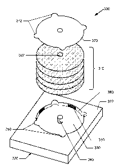
A spindle packaging tray for holding a plurality of discs,
the tray including: a depression designed to hold the plurality of discs, the
depression including an inner wall that is at least partially ridged to
pro-vide stability for the plurality of discs to stay snug inside the
depression; a
spindle formed inside the depression, the spindle designed to help keep the
plurality of discs in place; and a plurality of holes designed to allow
con-sumers to easily insert or remove the plurality of discs to and from the
de-pression. Keywords include spindle, ridged inner wall, and tray.
Plateau de rangement à mandrin pouvant recevoir une pluralité de disques, qui comprend: un renfoncement présentant une paroi intérieure partiellement rainurée destiné à asseoir la stabilité de disques disposés de manière lâche dans le renfoncement; un mandrin formé à l'intérieur du renfoncement, conçu pour maintenir en place la pluralité de disques; et une pluralité de découpes permettant d'insérer et d'extraire facilement la pluralité de disques dans ou hors de renfoncement. Mots clés: mandrin, paroi intérieure rainurée; plateau.
Note: Claims are shown in the official language in which they were submitted.
Note: Descriptions are shown in the official language in which they were submitted.
2024-08-01:As part of the Next Generation Patents (NGP) transition, the Canadian Patents Database (CPD) now contains a more detailed Event History, which replicates the Event Log of our new back-office solution.
Please note that "Inactive:" events refers to events no longer in use in our new back-office solution.
For a clearer understanding of the status of the application/patent presented on this page, the site Disclaimer , as well as the definitions for Patent , Event History , Maintenance Fee and Payment History should be consulted.
| Description | Date |
|---|---|
| Time Limit for Reversal Expired | 2016-05-27 |
| Letter Sent | 2015-05-27 |
| Grant by Issuance | 2014-10-28 |
| Inactive: Cover page published | 2014-10-27 |
| Inactive: Final fee received | 2014-08-15 |
| Pre-grant | 2014-08-15 |
| Letter Sent | 2014-02-24 |
| Notice of Allowance is Issued | 2014-02-24 |
| Notice of Allowance is Issued | 2014-02-24 |
| Inactive: Approved for allowance (AFA) | 2014-02-21 |
| Inactive: Q2 passed | 2014-02-21 |
| Amendment Received - Voluntary Amendment | 2013-08-26 |
| Inactive: S.30(2) Rules - Examiner requisition | 2013-02-25 |
| Letter Sent | 2011-03-17 |
| Request for Examination Requirements Determined Compliant | 2011-03-09 |
| Request for Examination Received | 2011-03-09 |
| All Requirements for Examination Determined Compliant | 2011-03-09 |
| Inactive: Notice - National entry - No RFE | 2011-02-18 |
| Inactive: Applicant deleted | 2011-02-18 |
| Inactive: Applicant deleted | 2011-02-18 |
| Inactive: Cover page published | 2011-02-10 |
| Inactive: Notice - National entry - No RFE | 2011-01-26 |
| Inactive: First IPC assigned | 2011-01-19 |
| Inactive: IPC assigned | 2011-01-19 |
| Inactive: IPC assigned | 2011-01-19 |
| Inactive: IPC assigned | 2011-01-19 |
| Application Received - PCT | 2011-01-19 |
| National Entry Requirements Determined Compliant | 2010-11-26 |
| Application Published (Open to Public Inspection) | 2009-12-23 |
There is no abandonment history.
The last payment was received on 2014-05-06
Note : If the full payment has not been received on or before the date indicated, a further fee may be required which may be one of the following
Patent fees are adjusted on the 1st of January every year. The amounts above are the current amounts if received by December 31 of the current year.
Please refer to the CIPO
Patent Fees
web page to see all current fee amounts.
| Fee Type | Anniversary Year | Due Date | Paid Date |
|---|---|---|---|
| Basic national fee - standard | 2010-11-26 | ||
| Request for examination - standard | 2011-03-09 | ||
| MF (application, 2nd anniv.) - standard | 02 | 2011-05-27 | 2011-05-06 |
| MF (application, 3rd anniv.) - standard | 03 | 2012-05-28 | 2012-05-01 |
| MF (application, 4th anniv.) - standard | 04 | 2013-05-27 | 2013-05-02 |
| MF (application, 5th anniv.) - standard | 05 | 2014-05-27 | 2014-05-06 |
| Final fee - standard | 2014-08-15 |
Note: Records showing the ownership history in alphabetical order.
| Current Owners on Record |
|---|
| SONY PICTURES ENTERTAINMENT INC. |
| SONY CORPORATION |
| Past Owners on Record |
|---|
| ANDY ALVAREZ |
| MARC RASHBA |
| THOMAS DOHNER |

