Note: Descriptions are shown in the official language in which they were submitted.
CA 02726295 2010-12-22
CROSS VENTILATION CURTAIN SYSTEM
FIELD OF THE INVENTION
This invention relates generally to roll-up curtain systems and is
particularly directed to
an arrangement of vertically spaced roll-up curtain sections for controlling
the flow of moist air
through a generally closed structure.
BACKGROUND OF THE INVENTION
Flexible, lightweight curtain systems are increasingly being used as outer
walls for
structures housing animals in agricultural environments. These movable curtain
systems
frequently include long spans of vertically spaced roll-up curtain sections
which are opened and
closed for the purpose of controlling the environment within the structure for
the benefit of the
animals therein. The curtains are opened at high temperatures, closed at low
temperatures, and
are intermediately positioned at moderate temperatures. The goal is to
precisely control the
openings formed by the curtains for optimum comfort of the animals.
As the length and weight of the curtain sections increases to accommodate
larger building
structures, the curtain support and drive mechanisms have increased in size
and complexity.
This trend has made it more difficult to precisely control the extent to which
the curtain sections
are open or closed. This has also led to increased size and numbers of
support/control
mechanisms which has reduced the open portion of the curtain wall through
which air flows into
and out of the structure.
The present invention addresses the aforementioned limitations of the prior
art by
providing a compact support/control mechanism capable of vertically displacing
long sections of
vertically spaced curtains for precisely controlling airflow into and out of a
generally closed
structure. In addition, the present invention contemplates the use of water
curtains disposed
2
CA 02726295 2015-10-26
adjacent to and inwardly of the curtain sections for directing in a controlled
manner moist air
through the enclosed space in precisely controlling the environment therein
for optimum
comfort.
SUMMARY OF THE INVENTION
According, the present invention seeks to provide improved cooling in a
generally closed
space by adding water to an airflow through the space and selectively
controlling the airflow
throughout the space.
Another aspect of the present invention seeks to provide improved cooling for
animals in
a generally closed space by controlling the rate of flow of moist air through
the space to allow
for increased relative humidity of the air while avoiding condensation on the
animals.
A further aspect of the present invention seeks to provide a multi-section
curtain
arrangement forming a wall of a generally closed room through which air is
drawn which allows
for precise control of airflow through the room and the environment within the
room.
Yet another aspect of the present invention seeks to provide a multi-section
roll-up
curtain arrangement forming a wall of a generally closed room which allows for
increased
airflow through the room by minimizing the width of the curtain roll-up drive
and support
mechanism.
A still further aspect of the present invention seeks to provide a multi-
section roll-up
curtain arrangement forming a wall which provides increased comfort at high
outside
temperatures for cows in a milking parlor.
Another aspect of the present invention seeks to roll-up or unroll plural
vertically aligned
curtain sections independently of one another to provide more precise control
of the openings
between adjacent curtain sections and the flow of air through the curtain
sections.
3
CA 02726295 2015-10-26
A further aspect of the present invention seeks to provide a roll-up curtain
system for
controlling air flow through a generally closed space capable of operating
equally well under
either manual operation or motor driven operation.
The present invention contemplates for use in a generally closed space defined
by plural
structural members and having first and second spaced lateral peripheral
portions, wherein air is
drawn through the first lateral peripheral portion into the space and exits
via the second lateral
peripheral portion, and wherein water is introduced in the airflow for cooling
the space, an
arrangement for controlling the moist airflow in the enclosed space
comprising: first upper, first
intermediate and first lower curtain sections arranged in vertical spaced
alignment and covering
the first lateral peripheral portion of the space, wherein each of the first
upper, intermediate and
lower curtain sections includes a respective upper edge portion fixedly
attached to a structural
member and a respective free lower edge portion attached to a respective roll-
up rod; first,
second and third rotary drive and trolley combinations each respectively
coupled to a respective
roll-up rod of said first upper, intermediate and lower curtain sections for
independently rolling
up or unrolling the curtain sections relative to a fixed upper edge portion of
the curtain section,
wherein a rotary drive and trolley combination moves upward to roll-up its
associated curtain
section and moves downward to unroll its associated curtain section; and a
vertical guide coupled
to the rotary drive and trolley combinations for limiting movement of the roll-
up rods attached to
a lower edge portion of each curtain section to a generally vertical plane
during rolling up and
unrolling of the curtain sections in controlling airflow in the generally
closed space, the vertical
guide including a first track arrangement engaging the first and third rotary
drive and trolley
combinations and a second track arrangement engaging the second rotary drive
and trolley
combination, wherein the first and second track arrangements are arranged in a
horizontally
4
CA 02726295 2015-10-26
spaced manner from one another allowing the first and third rotary drive and
trolley
combinations and the second rotary drive and trolley combination to move
upward and
downward in a vertically offset manner.
The present invention contemplates for use in a generally closed space defined
by plural
structural members and having a first lateral peripheral portion, an
arrangement for controlling
airflow in the generally closed space comprising: first upper, first
intermediate and first lower
curtain sections arranged in vertical spaced alignment and covering the first
lateral peripheral
portion of the space, wherein each of the first upper, intermediate and lower
curtain sections
includes a respective upper edge portion fixedly attached to a structural
member and a respective
free lower edge portion attached to a respective roll-up rod; first, second
and third rotary drive
and trolley combinations each respectively coupled to a roll-up rod of the
first upper,
intermediate and lower curtain sections for independently rolling up or
unrolling the curtain
sections relative to the fixed upper edge portion of the curtain section,
wherein each rotary drive
and trolley combination moves upward to roll-up its associated curtain section
and moves
downward to unroll its associated curtain section; a vertical guide coupled to
the rotary drive and
trolley combinations for limiting movement of the roll-up rods attached to a
lower edge portion
of each curtain section to a generally vertical plane during rolling up and
unrolling of the curtain
sections in controlling airflow in the generally closed space, the vertical
guide including a first
track arrangement engaging the first and third rotary drive and trolley
combinations and a second
track arrangement engaging the second rotary drive and trolley combination,
wherein the first
and second track arrangements are arranged in a horizontally spaced manner
from one another
for maintaining the first and third rotary drive and trolley combinations in a
horizontally spaced
manner from the second rotary drive and trolley combination and allowing the
first and third
5
CA 02726295 2015-10-26
'
rotary drive and trolley combinations and the second rotary drive and trolley
combination to
move upward and downward in a vertically offset manner; and an air
displacement device for
directing an airflow between the curtain sections and into the generally
closed space; and at least
one mist device disposed in or adjacent to the generally closed space for
introducing moisture in
the airflow through the curtain sections and within the generally closed
space.
BRIEF DESCRIPTION OF THE DRAWINGS
The appended claims set forth those novel features which characterize the
invention.
However, the invention itself, as well as further aspects and advantages
thereof, will best be
understood by reference to the following detailed description of a preferred
embodiment taken in
conjunction with the accompanying drawings, where like reference characters
identify like
elements throughout the various figures, in which:
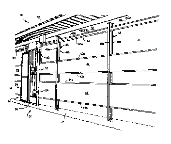
FIG. 1 is a perspective view of the outside of a multi-section curtain system
forming an
outer wall of a generally enclosed structure;
FIG. 2 is an outer perspective view of a second wall in the structure which
includes the
multi-curtain system shown in FIG. 1, where the wall shown in FIG. 2 includes
plural-spaced
exhaust fans for moving air through the spaced defined by the structure;
FIG. 3 is a perspective view of a multi-drive arrangement for use in
individually
controlling the multi-section curtain system of the present invention;
FIG. 4 is a perspective view of an upper portion of the curtain drive and
support
arrangement for use in the cross ventilation curtain system of the present
invention;
FIG. 5 is a perspective view showing the position of a pair of support/drive
mechanisms
for use in the cross ventilation curtain system of the present invention;
5A
CA 02726295 2015-10-26
FIG. 6 is a perspective view showing additional details of a curtain
support/drive
mechanism used in a preferred embodiment of the cross ventilation curtain
system of the present
invention;
5B
CA 02726295 2010-12-22
FIG. 7 is a perspective view of a curtain support/drive mechanism used in a
preferred
embodiment of the present invention; and
FIG. 8 is a front perspective view of another embodiment of the present
invention
employing a manual drive arrangement for rolling up and unrolling the curtain
sections.
DETAILED DESCRIPTION OF THE PREFERRED EMBODIMENTS
Referring to FIG. 1, there is shown an outer perspective view of a cross
ventilation
curtain system 30 in accordance with the principles of the present invention.
FIG. 2 is a
perspective view of a second wall 33 of the structure 28 in which the cross
ventilation curtain
system 30 of the present invention is incorporated. FIG. 3 is a front
perspective view of a curtain
controller 58 for use in the cross ventilation curtain system 30 of the
present invention. FIG. 4 is
a lower perspective view of an upper portion of the curtain controller 58 for
supporting and
controlling the upper curtain sections of the inventive cross ventilation
curtain system 30. FIG. 5
is a perspective view of a portion of the cross ventilation curtain system's
curtain controller 58
showing additional details of the drive and support arrangements for the upper
and intermediate
curtain sections of the cross ventilation curtain system. FIG. 6 is a
perspective view of the lower
support/drive mechanism 54 used in supporting and controlling the operation of
the cross
ventilation curtain system's lower curtain sections. FIG. 7 is a perspective
view of the lower
support/drive mechanism 54 which provides support and control of the cross
ventilation curtain
system's lower curtain sections, it being understood that the corresponding
support/drive
mechanisms for the cross ventilation curtain system's upper and intermediate
curtain sections are
the same in configuration, structure and operation as the support/drive
mechanism shown in
FIG. 7 for the lower curtain sections.
6
CA 02726295 2010-12-22
Cross ventilation curtain system 30 forms one wall of a generally closed
structure 28
which also includes a roof 32 and a second wall shown as element 33 in the
perspective view of
FIG. 2. As shown in FIG. 2, an upper portion of the second wall 33 adjoins the
structure's roof
32 and is positioned on and supported by the structure's foundation, or floor,
34. The second
wall 33 is comprised of plural exhaust fans 35 which draw air through the
first wall formed of
the cross ventilation curtain system 30. After the flow of air passes through
the cross ventilation
curtain system 30, it transits the interior space of the structure 28 and
exits the structure via the
plural exhaust fans 35 forming the structure's second wall 33. Disposed within
the structure in
closely spaced relation to the cross ventilation curtain system 30 is a water
curtain 31 which
extends the height and width of the cross ventilation curtain system as shown
in FIG. 1. Water
curtain 31 is conventional in design and operation and is comprised of an air
permeable material
with water retention properties. In operation, water is deposited on the upper
edge portion of the
water curtain 31 and is allowed to travel downward on the water curtain so as
to introduce
moisture in the flow of air drawn through the water curtain by the
aforementioned exhaust fans
35 disposed in a spaced manner across the structure from the water curtain. By
directing airflow
through the water-bearing water curtain 31, cool moist air is drawn through
the interior space of
the structure by means of the aforementioned exhaust fans 35. In the
environment in which the
cross ventilation curtain system 30 of the present invention is intended for
use, the moist air is
used to maintain a cool, comfortable environment for the benefit of cows being
milked within the
structure. The cross ventilation curtain system 30 of the present invention
allows for precise
control of airflow through the water curtain 31 so as to provide a desired
moisture level within
the airflow for optimum comfort, while preventing condensation of the moisture
on the animals
and the undesirable health impact that this would have on them. In another
embodiment,
7
CA 02726295 2010-12-22
moisture is introduced in the airflow between the curtain sections 40, 42 and
44 and through the
interior space of structure 28 not by the water curtain 31, but rather by at
least one mist device
disposed in or adjacent to the generally closed structure 28, where two mist
devices 29a and 29b
are shown in FIG. 1. These mist devices 29a, 29b introduce water in the form
of a fine mist as it
passes between curtain sections 40, 42 and 44 and flows through the interior
space of the
structure 28.
Cross ventilation curtain system 30 includes the aforementioned first upper,
intermediate
and lower curtain sections 40,42 and 44 disposed in spaced vertical alignment
and extending
laterally over an outer portion of the structure 28. Disposed adjacent one end
of each of the first
upper, intermediate and lower curtain sections 40, 42 and 44 are second upper,
intermediate and
lower curtain sections 60, 62 and 64. Disposed between the first and second
curtain sections is a
curtain controller 58. Curtain controller 58 simultaneously controls the
operation of each of the
first and second upper, intermediate and lower curtain sections as described
in detail below. The
following description is directed to the first upper, intermediate and lower
curtain sections 40, 42
and 44, it being understood that this description applies equally as well to
the construction,
configuration and operation of the second upper, intermediate and lower
curtain sections 60, 62
and 64.
An upper edge portion of the first upper curtain section 40 is securely
attached to an
upper structural member 56 of the structure 28 in a conventional manner such
as by fasteners or
by a mounting member (not shown). The lower end portion of the first upper
curtain section 40
is in the form of a hem 40a which is adapted to receive a first curtain
drive/support rod 122
which is shown in FIG. 4. The upper edge portion 42b of the intermediate
curtain section 42 is
adapted to receive an upper support rod 42c disposed within a hem formed in
the upper edge
8
CA 02726295 2010-12-22
portion. The intermediate curtain section's upper support rod 42c is securely
attached to the
housing 36 of the curtain controller 58 as well as to first and second
guide/support arrangement
46 and 48 disposed in a spaced manner along the lengths of the first upper,
intermediate and
lower curtain sections 40,42 and 44. The first and second guide/support
arrangements 46, 48
respectively include outer and inner members 46a, 46b and 48a, 48b for
engaging the outer and
inner surfaces of the three curtain sections and maintaining these curtain
sections in generally
vertical alignment when in fixed position as well as during unrolling and roll-
up of the curtain
sections. In addition, the first and second guide/support arrangements 46, 48
are attached to and
provide support for the first intermediate and lower curtain sections 42 and
44. Thus, an upper
edge portion 44b of the first lower curtain section 44 is coupled to an
elongated, linear support
rod 44c which, in turn, is attached to the housing 36 of the curtain
controller 58 as well as to the
first and second guide/support arrangements 46 and 48 for supporting the first
lower curtain
section. The first lower curtain section 44 is also provided with a curtain
hem 44a on its lower
edge which contains a third curtain drive rod 108 described below. Each of the
second upper,
intermediate and lower curtain sections 60, 62 and 64 is configured, mounted
and positioned
within structure 28 and operates in a manner similar to that of the above
described first upper,
intermediate and lower curtain sections 40, 42 and 44.
Referring to FIG. 3, details of the configuration and operation of the cross
ventilation
curtain system's controller 58 will now be described. Curtain controller 58
includes a generally
closed housing 36 including a rectangular frame and a top panel 37, a rear
wall 39, and a
pivoting front door 38 for enclosing the various support and control
mechanisms described in
detail below. Curtain controller 58 further includes a first upper
support/drive mechanism 50 for
providing support and control for the first and second upper curtain sections
40, 60. Curtain
9
CA 02726295 2010-12-22
controller 58 also includes a second intermediate support/drive mechanism 52
and a third lower
support/drive mechanism 54 for providing support and control respectively for
the intermediate
curtain sections 42, 62 and for the lower curtain sections 44, 64. Disposed
within the curtain
controller 58 are first, second and third vertical guide members 70, 72 and 74
which extend from
the top of the first and second upper curtain sections 40, 60 to the bottom of
the first and second
lower curtain sections 44, 64. The first, second and third vertical guide
members 70, 72 and 74
engage and maintain the first upper, second intermediate and third lower
support/drive
mechanisms 50, 52 and 54 in a fixed orientation and in vertical alignment
during rolling up and
unrolling of the various curtain sections as well as when the curtain sections
are in fixed position.
Curtain controller 58 further includes three pairs of upper and lower limit
switches, with
each pair of limit switches controlling the upper and lower position limits of
a respective one of
the support/drive mechanisms. Thus, limit switch 80 limits the lowest position
of the first upper
support/drive mechanism 50. An upper limit switch limits the uppermost
position of the first
upper support/drive mechanism 50, but this limit switch is now shown in the
figures for
simplicity. Similarly, second upper and lower limit switches 82a and 82b
respectively limit the
uppermost and lowest positions of the second intermediate support/drive
mechanism 52. Finally,
third upper and lower limit switches 84a and 84b limit the uppermost and
lowest positioning
limits of the third lower support/drive mechanism 54. As shown for the case of
the second upper
limit switch 82a in FIG. 4, each of the limit switches includes a pivoting arm
which is identified
as element 83 for the second upper limit switch. A position limit switch is
triggered when a
curtain drive/support rod attached to a lower or intermediate hem portion of a
curtain section
engages and displaces the limit switch's pivoting arm which results in
termination of further
movement of the curtain section's lower or intermediate hem portion.
CA 02726295 2010-12-22
The structure, configuration and operation of a support/drive mechanism used
for
supporting and controlling each of the curtain sections will now be described
in detail in terms of
FIGS. 6 and 7. FIG. 6 is a perspective view of the third lower support/drive
mechanism 54
installed in the cross ventilation curtain system 30 of the present invention,
while FIG. 7 is a
perspective view of this support/drive mechanism removed from the system to
illustrate
additional details of its structure and components. The first upper and second
intermediate
support drive mechanisms 50, 52 are configured and operate similarly to the
third lower
support/drive mechanism 54. The third lower support/drive mechanism 54
includes a generally
planar support panel 92 comprised of a high strength material such as metal or
plastic. The third
lower support/drive mechanism 54 further includes the combination of an
electric motor 54a and
a gearbox 91 as well as a trolley mechanism 54b. As shown in FIG. 6, electric
motor 54a is
energized by a source of electricity via electrical lead 90. Rotational
displacement of an output
shaft (not shown) of electric motor 54a is converted to the proper RPMs by
gearbox 91 which is,
in turn, coupled to a first drive shaft 96. The combination of electric motor
54a and gearbox 91
is securely mounted to support panel 92 by means of first and second mounting
brackets 94a and
94b which are connected to the gearbox. Disposed on opposed ends of the first
drive shaft 96 are
first and second sprockets 98a and 98b. First and second sprockets 98a, 98b
are respectively
coupled by means of first and second drive chains 100 and 102 to third and
fourth sprockets 110a
and 110b. The third and fourth sprockets 110a, 110b are mounted on opposed
ends of a second
drive shaft 106 which is mounted to the support panel 92 by means of the
combination of a
mounting bracket 136 and a nut and bolt combination 138. One end of the second
drive shaft
106 is connected to a first curtain drive/support rod 104, while an opposed
end of the second
drive shaft is connected to a second curtain drive/support rod 108. The first
curtain drive/support
11
CA 02726295 2010-12-22
rod 104 is connected to a lower hem portion of the second lower curtain
section 64, while the
second curtain drive/support rod 108 is connected to a lower hem portion of
the first lower
curtain section 44. It should be noted here that the second drive shaft 106
may also be connected
to an intermediate hem portion of a curtain section as shown for the case of a
drive shaft 136 of
the second intermediate support/drive mechanism 52 connected to intermediate
hems of the first
and second intermediate curtain sections 42, 62. Thus, in accordance with the
present invention,
the combination of a support/drive mechanism may be connected to an
intermediate hem or a
bottom hem of a curtain section. Rotational displacement of the output shaft
(not shown) of
electric motor 54a is converted and transmitted via the combination of gearbox
91, first drive
shaft 96, first and second sprockets 98a, 98b, first and second drive chains
100, 102, third and
fourth sprockets 110a, 110b, and second drive shaft 106 to the proper
rotational speed for rolling
up and unrolling the first and second lower curtain sections 44 and 64. It
should also be noted
here that while the aforementioned support/drive mechanisms are each described
as including an
electric motor, the present invention is not limited to the use of electric
motors and may make
use of virtually any source of rotational motion properly sized and scaled,
including a manual
drive mechanism as described in detail below.
The trolley mechanism 54b of the third lower support/drive mechanism 54
includes its
support panel 92 to which are rotationally mounted first, second, third and
fourth rollers 112a -
112d. Each of the aforementioned rollers, or wheels, 112a ¨ 112d are by means
of a respective
axle, such as shown for the case of the third and fourth rollers 112c, 112d,
respectively attached
to the support panel by means of axles 114a and 114b. Each of the rollers 112a
- 112d is adapted
for engagement with a respective one of the second and third vertical guide
members 72, 74 and
to the controller housing's rear wall 39. Thus, rollers 112a and 112d are
adapted for engagement
12
CA 02726295 2010-12-22
with second vertical guide member 72 and rear wall 39, while rollers 112b and
112c are adapted
for engagement with third vertical guide member 74 and the rear wall. Thus,
rollers 112a - 112d
are positioned between and in contact with the housing's rear wall 39 and a
respective one of the
first, second or third vertical guide members 70, 72 and 74 for limiting
movement of the three
support/drive mechanisms 50, 52 and 54 to a vertical plane for insuring
vertical alignment and
displacement of the curtain sections.
The use of only three vertical guide members and two vertical offset paths of
travel of the
three support/drive mechanisms 50, 52 and 54 minimizes the horizontal width of
the curtain
controller's housing 36 to allow for increased curtain section lengths in
spanning the opening in
a lateral portion of structure 28. This permits additional air to be moved
through the space
within structure 28 and allows for enhanced control of the environment within
the structure's
inner space. The vertically offset curtain drive arrangement of the present
invention also allows
the plural vertically aligned curtain sections to be individually and
independently rolled up or
unrolled to provide more precise control of the extent of airflow between
adjacent curtain
sections as well as through the entire roll-up curtain arrangement. In
addition, by optimally
orienting the components of each of the three support/drive mechanisms 50, 52
and 54, the
vertical dimensions of the curtain controller's housing 36 is also minimized
and vertical
displacement of the upper and lower curtain support/drive mechanisms is
increased. More
particularly, the orientation of the respective motors 50a and 54a in the
first upper and third
lower support/drive mechanisms 50, 54 is reversed eliminating the requirement
to expand the
vertical dimensions of housing 36, while still allowing the first, second and
third curtain sections
to fully span the vertical dimension of the lateral opening in structure 28.
Positioning electric
motors 50a and 50b in opposed relative orientations allows for a reduction in
the vertical
13
CA 02726295 2015-10-26
dimension of housing 36 and increases the vertical dimensions of the openings
provided by the
upper and lower curtain sections when rolled up to increase the flow of air
through structure 28.
Referring to FIG. 8, there is shown another embodiment of a cross ventilation
curtain
system in accordance with the principles of the present invention. The cross
ventilation curtain
system shown in FIG. 8 is similar to the cross ventilation curtain system
shown in FIG. 3. Thus,
common elements in both of the cross ventilation curtain systems shown in
FIGS. 3 and 8 having
the same configuration and performing the same function have been provided
with the same
identifying element number in the two figures. The different between the two
cross ventilation
curtain systems shown in FIGS. 3 and 8 is in the manner in which the
individual curtain sections
are rolled up and unrolled. More specifically, the cross ventilation curtain
system shown in
FIG. 3 employs first, second and third electric motors 50a, 52a and 54a to
raise and lower the
upper, intermediate and lower curtain sections 40, 42 and 44, respectively. In
the embodiment of
applicant's invention shown in FIG. 8, the upper, intermediate and lower
curtain sections 40, 42
and 44 are raised and lowered by means of first, second and third mechanical
drives 140, 142
and 144. Each of the first, second and third mechanical drives 140, 142 and
144 is adapted for
providing rotary drive for an associated coupled curtain section by means of a
power unit 146,
which in FIG. 8 is shown as a conventional electric drill. Power unit 146 is
adapted for engaging
and rotationally driving by means of an extension rod 148 a respective adapter
140a, 142a and
144a disposed in the first, second and third mechanical drives 140, 142 and
144.
While particular embodiments of the present invention have been described, it
will be
obvious to those skilled in the relevant arts that changes and modifications
may be made without
departing from the invention in its broader aspects. Therefore, the aim in the
appended claims is
to cover all such changes and modifications that fall within the true scope of
the
14
CA 02726295 2010-12-22
invention. The matters set forth in the foregoing description and accompanying
drawings is
offered by way of illustration only and is not a limitation. The actual scope
of the invention is
intended to be defined in the following claims when viewed in their proper
perspective based on
the prior art.
15