Language selection

Search

Patent 2726637 Summary

Third-party information liability

Some of the information on this Web page has been provided by external sources. The Government of Canada is not responsible for the accuracy, reliability or currency of the information supplied by external sources. Users wishing to rely upon this information should consult directly with the source of the information. Content provided by external sources is not subject to official languages, privacy and accessibility requirements.

Claims and Abstract availability

Any discrepancies in the text and image of the Claims and Abstract are due to differing posting times. Text of the Claims and Abstract are posted:

  • At the time the application is open to public inspection;
  • At the time of issue of the patent (grant).
(12) Patent: (11) CA 2726637
(54) English Title: HYDRAULIC CLAMPING DEVICE
(54) French Title: DISPOSITIF DE SERRAGE HYDRAULIQUE
Status: Granted and Issued
Bibliographic Data
(51) International Patent Classification (IPC):
  • E21B 19/16 (2006.01)
  • B25B 13/50 (2006.01)
(72) Inventors :
  • WEBB, JONATHAN GARRICK (Norway)
(73) Owners :
  • GRANT PRIDECO, INC.
(71) Applicants :
  • GRANT PRIDECO, INC. (United States of America)
(74) Agent: SMART & BIGGAR LP
(74) Associate agent:
(45) Issued: 2016-04-05
(86) PCT Filing Date: 2009-06-15
(87) Open to Public Inspection: 2009-12-23
Examination requested: 2014-04-04
Availability of licence: N/A
Dedicated to the Public: N/A
(25) Language of filing: English

Patent Cooperation Treaty (PCT): Yes
(86) PCT Filing Number: PCT/NO2009/000221
(87) International Publication Number: WO 2009154469
(85) National Entry: 2010-12-01

(30) Application Priority Data:
Application No. Country/Territory Date
20082732 (Norway) 2008-06-18

Abstracts

English Abstract


A hydraulic clamping
device (1), wherein a clamping piece (4)
is supported in a structure (2), and
wherein a cylinder housing (36) of a
hy-draulic cylinder (26) is fixedly
connect-ed to the structure (2), the hydraulic
cylinder (26) being arranged to exert,
along a longitudinal axis (42) of the
cylinder (26), a force against the
clamp-ing piece, and wherein a piston (32) in
the hydraulic cylinder (26) is isolated
from the clamping piece (6) with respect
to forces acting perpendicularly relative
to the longitudinal axis (42).


French Abstract

La présente invention concerne un dispositif de serrage hydraulique (1), dans lequel une pièce de serrage (4) est montée dans une structure (2), et dans lequel un boîtier de vérin (36) dun vérin hydraulique (26) est connecté de manière fixe à la structure (2), le vérin hydraulique (26) étant agencé pour appliquer, selon un axe longitudinal (42) du vérin (26), une force contre la pièce de serrage, et dans lequel un piston (32) dans le vérin hydraulique (26) est isolé de la pièce de serrage (6) par rapport aux forces agissant perpendiculairement par rapport à laxe longitudinal (42).

Claims

Note: Claims are shown in the official language in which they were submitted.

Claims
1. A hydraulic clamping device, comprising:
a clamping piece supported in a structure;
a hydraulic cylinder having a longitudinal axis and including a cylinder
housing
fixedly connected to the structure and a piston moveably disposed in the
cylinder housing;
an intermediate piece axially disposed between the piston and the clamping
piece;
and
a bearing axially disposed between the piston and the intermediate piece;
wherein the hydraulic cylinder is configured to exert a force along the
longitudinal
axis against the clamping piece;
wherein the clamping piece is coupled to the intermediate piece through a
first pair of
mating spherical surfaces in sliding engagement, wherein a first surface of
the
first pair of mating spherical surfaces is disposed on the clamping device and
a second surface of the first pair of mating spherical surfaces is disposed on
the intermediate piece;
wherein the intermediate piece is coupled to the bearing through a second pair
of
mating spherical surfaces in sliding engagement, wherein a first surface of
the
second pair of mating spherical surfaces is disposed on the intermediate piece
and a second surface of the second pair of mating spherical surfaces is
disposed on the bearing.
2. The hydraulic clamping device of claim 1, wherein a support in the
structure for the
clamping piece comprises a guide.
3. The hydraulic clamping device of claim 1, wherein a support in the
structure for the
clamping piece comprises a pivot-bearing.
4. The hydraulic clamping device of claim 1, further comprising a strut
extending
axially through the intermediate piece and having a first end and a second end
opposite the
8

first end, wherein the first end is directly connected to the piston and the
second end is
directly connected to the clamping piece.
5. The hydraulic clamping device of claim 1, further comprising a plurality
of guides
that cooperate with the clamping piece and are fixedly connected to the
structure.
6. The hydraulic clamping device of claim 1, wherein a displacement
direction of the
clamping piece substantially coincides with a displacement direction of the
piston.
7. The hydraulic clamping device of claim 1, wherein the cylinder housing
is positioned
outside the structure.
8. The hydraulic clamping device of claim 1, wherein the first surface of
the first pair of
mating spherical surfaces comprises a convex spherical surface;
wherein the second surface of the first pair of mating spherical surfaces
comprises a
concave spherical surface;
wherein the first surface of the second pair of mating spherical surfaces
comprises a
convex spherical surface; and
wherein the second surface of the second pair of mating spherical surfaces
comprises
a concave spherical surface.
9

Description

Note: Descriptions are shown in the official language in which they were submitted.


CA 02726637 2010-12-01
WO 2009/154469 PCT/N02009/000221
HYDRAULIC CLAMPING DEVICE
This invention relates to a hydraulic clamping device. More
particularly, it relates to a hydraulic clamping device,
:wherein a clamping piece is supported in a structure, and
wherein a cylinder housing of a hydraulic cylinder is fixedly
connected to the structure, the hydraulic cylinder being
arranged to exert, along a longitudinal axis thereof, a force
against the clamping piece.
To be able to isolate a hydraulic cylinder from the forces
acting perpendicularly to the piston in the cylinder, and in
the displacement direction, it is common to connect the
cylinder housing to a structure by means of a pivotal
mounting. Preferably, mountings of this sort should be
pivotal about at least two axes, therefore being relatively
space-demanding.
Oftentimes known cylinder mountings require the cylinder to
be at least partly incorporated into the structure, which may
limit the cylinder diameter possible, thereby requiring use
of a pressure booster to obtain sufficient force.
Incorporated cylinders may also complicate the conveyance of
pipes onwards to the cylinder.
1

CA 02726637 2010-12-01
WO 2009/154469 PCT/N02009/000221
A link-supported cylinder requires pressurised fluid to be
supplied via a flexible connection, for example a hose, or
via a pivotal coupling. Hoses and pivotal couplings
constitute components prone to leaks.
The object of the invention is to remedy or reduce at least
one of the disadvantages of the prior art.
The object is achieved in accordance with the invention and
the features disclosed in the following description and in
the subsequent claims.
A hydraulic clamping device is provided, wherein a clamping
piece is supported in a structure, and wherein a cylinder
housing of a hydraulic cylinder is fixedly connected to the
structure, the hydraulic cylinder being arranged to exert,
along a longitudinal axis thereof, a force against the
clamping piece. The hydraulic clamping device is
characterized in that a piston in the hydraulic cylinder is
isolated from the clamping piece with respect to forces
acting perpendicularly relative to the longitudinal axis.
Forces acting on the clamping piece in other directions than
the longitudinal direction of the cylinder are thereby
transmitted only to a limited extent to the piston in the
cylinder. Thus it is avoided that the cylinder's piston rod
must be able to withstand a bending moment, which
considerably simplifies the cylinder structure.
The support in the structure for the clamping piece may, for
example, be comprised of a guide or a pivot-bearing.
The guide or.the pivot-bearing is arranged so as to be able
to withstand the forces acting on the clamping piece in other
directions than the axial direction of the cylinder. The
guide may be comprised of several cooperating guide surfaces
2

CA 02726637 2010-12-01
WO 2009/154469 PCT/N02009/000221
allowing for displacement of the clamping piece in one
direction. A pivot-bearing may, for example, comprise a shaft
with an associated bearing.
The hydraulic cylinder may be connected to the clamping piece
by means of an intermediate piece, wherein the intermediate
piece may be provided with a pivot-bearing in at least one of
its end portions. The pivot-bearing may comprise a spherical
portion.
The intermediate piece may be arranged so as to be able to
only transmit forces between the piston and the clamping
piece in a first direction, whereas a strut may be arranged
so as to be able to transmit forces between the piston and
the clamping piece in an opposite direction. In an
alternative embodiment, the clamping piece may be biased in
the direction toward the cylinder, for example by means of a
spring.
The coupling between the piston and the intermediate piece,
as well as between the clamping piece and the intermediate
piece, may thus be comprised of uncomplicated structures,
insofar as the force transmitted via the intermediate piece
only constitutes a compressive force.
For example, the strut may be comprised of a bolt extending
through the clamping piece and the intermediate piece and
into the piston. Thereby, the strut entrains the clamping
piece when the piston is displaced in its negative direction.
Advantageously, the strut has a radial clearance in the
clamping piece and the intermediate piece, whereby a certain
radial displacement of the clamping piece and the
intermediate piece may take place without exposing the strut
to bending forces.
3

CA 02726637 2010-12-01
WO 2009/154469 PCT/N02009/000221
Several clamping pieces, which are connected to their
respective hydraulic cylinders, may be cooperating. This is
advantageous when, for example, pipes are to be gripped, and
where the pipe diameters may vary from time to time.
Guides cooperating with the clamping piece may be fixedly
connected to the structure. Thereby, a stable and relatively
compact design is obtained.
Generally, the displacement direction of the clamping piece
may coincide with the displacement direction of the piston.
By having a substantially equal displacement direction,
transmission links may be avoided, for example.
Advantageously, the cylinder acts directly onto the clamping
piece via the intermediate piece.
The cylinder housing may be located outside the structure and
may, for example, be flanged onto the structure. Thus, the
structure does not restrict the cylinder diameter possible,
nor does it obstruct the conveyance of pipe connections
onwards to the cylinder.
A hydraulic clamping device in accordance with the invention
is particularly suitable for use in a power tong for gripping
around a pipe. The cylinder diameter may be selected based on
the required gripping force and fluid pressure available,
simultaneously allowing for a compact and robust design.
In the following, an example of a preferred embodiment is
described and depicted in the accompanying drawings, where:
Fig. 1 shows a plan view of a hydraulic gripping device in
accordance with the invention;
Fig. 2 shows a side view of the gripping device of fig. 1;
4

CA 02726637 2010-12-01
WO 2009/154469 PCT/N02009/000221
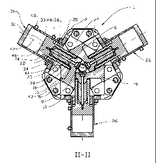
Fig. 3 shows, at a somewhat larger scale, a section II-II
shown in fig. 2;
Fig. 4 shows, at a somewhat larger scale, a section Ia-Ia
shown in fig. 1;
Fig. 5 shows, at a somewhat larger scale, a section Ib-Ib
shown in fig. 1; and
Fig. 6 is a perspective view of a clamping piece.
In the drawings, reference numeral 1 denotes a hydraulic
clamping device in the form of a power tong comprising a
structure 2, wherein the structure 2 is provided with guides
4.
A clamping piece 6 cooperates in a displaceable manner with
the guides 4. The clamping piece 6 is formed with a jaw 8
facing a pipe 10 to be gripped.
The clamping piece 6 is formed so as to be able to cooperate
with adjacent clamping pieces 6, insofar as one side of the
clamping piece 6 is given a fork-shape having an intermediate
recess 12, see fig. 6, and the opposite side thereof is
formed with an arm portion 14. During mutual displacement of
the clamping pieces 6, the recess 12 forms an opening for the
arm portion 14 of the adjacent clamping piece 6.
Opposite the jaw 8, the clamping piece 6 is formed with an
outwardly extending, spherical bulb 16 fitting in a
complementary manner within a spherical recess 18 in an
intermediate piece 20, see figs. 3 and 4. In the opposite end
thereof, the intermediate piece 20 is formed with a spherical
end portion 22 fitting within a spherical bearing 24.
A hydraulic cylinder 26 is fixedly connected to the structure
2 by means of a flange connection 28. A piston 32 with a
5

CA 02726637 2010-12-01
WO 2009/154469 PCT/N02009/000221
piston rod 34 extends within the cylinder housing 30 of the
hydraulic cylinder 26. The piston rod 34 extends in a
displaceable manner through an end wall 36. Required seals in
the cylinder are not shown.
The bulb 16, the intermediate piece 20 and the bearing 24 are
located in a central bore 38 in the piston rod 34 and are
sealed from the surroundings by means of a gasket 40 located
between the piston rod 34 and the clamping piece 6. The
bearing 24 abuts the bottom of the bore 28.
io A longitudinal axis 42 of the hydraulic cylinder 26 generally
coincides with the displacement direction of the clamping
piece 6.
A strut 44 in the form of a bolt extends through the clamping
piece 6, the intermediate piece 30, the bearing 24 and into a
threaded bore 46 in the piston 32. The strut 44 is arranged
so as to be able to entrain the clamping piece 6 when the
piston 32 is displaced in its negative direction. The. strut
44 is formed with some radial clearance relative to the
clamping piece 6 and the intermediate piece 20.
Pressurised fluid is supplied, in a manner known per se, to
ports 48 in the hydraulic cylinder 26.
In this embodiment, the clamping device 1 comprises three
clamping pieces 6 with associated cylinders 26, all of which
are formed as described above.
When the pipe 10 is to be gripped, the pistons 32 are
displaced in their positive direction and thus displace the
jaws 8 until engagement with the pipe 10, and by means of
respective bearings 24, intermediate pieces 20 and clamping
pieces 6.
6

CA 02726637 2010-12-01
WO 2009/154469 PCT/N02009/000221
The clamping force from the jaws 8 is transmitted to the
respective piston 32, whereas forces in other directions are
carried, in the tangential direction of the pipe 10, by the
guides 4 via the clamping piece 6, and are carried, in the
axial direction of the pipe 10, by supports 50 disposed
mutually between the clamping pieces 6, and between the
clamping pieces 6 and the structure 2.
7

Representative Drawing
A single figure which represents the drawing illustrating the invention.
Administrative Status

2024-08-01:As part of the Next Generation Patents (NGP) transition, the Canadian Patents Database (CPD) now contains a more detailed Event History, which replicates the Event Log of our new back-office solution.

Please note that "Inactive:" events refers to events no longer in use in our new back-office solution.

For a clearer understanding of the status of the application/patent presented on this page, the site Disclaimer , as well as the definitions for Patent , Event History , Maintenance Fee  and Payment History  should be consulted.

Event History

Description Date
Inactive: Recording certificate (Transfer) 2023-02-16
Inactive: Recording certificate (Transfer) 2023-01-16
Inactive: Multiple transfers 2022-12-06
Common Representative Appointed 2019-10-30
Change of Address or Method of Correspondence Request Received 2018-01-12
Grant by Issuance 2016-04-05
Inactive: Cover page published 2016-04-04
Pre-grant 2016-01-20
Inactive: Final fee received 2016-01-20
Notice of Allowance is Issued 2015-09-17
Letter Sent 2015-09-17
Notice of Allowance is Issued 2015-09-17
Inactive: Approved for allowance (AFA) 2015-08-19
Inactive: QS passed 2015-08-19
Amendment Received - Voluntary Amendment 2015-06-22
Inactive: S.30(2) Rules - Examiner requisition 2014-12-23
Inactive: Report - No QC 2014-12-09
Letter Sent 2014-04-10
Amendment Received - Voluntary Amendment 2014-04-04
Request for Examination Received 2014-04-04
Request for Examination Requirements Determined Compliant 2014-04-04
All Requirements for Examination Determined Compliant 2014-04-04
Inactive: Cover page published 2011-02-15
Letter Sent 2011-01-25
Inactive: Notice - National entry - No RFE 2011-01-25
Inactive: First IPC assigned 2011-01-21
Inactive: IPC assigned 2011-01-21
Application Received - PCT 2011-01-21
National Entry Requirements Determined Compliant 2010-12-01
Application Published (Open to Public Inspection) 2009-12-23

Abandonment History

There is no abandonment history.

Maintenance Fee

The last payment was received on 2015-05-14

Note : If the full payment has not been received on or before the date indicated, a further fee may be required which may be one of the following

  • the reinstatement fee;
  • the late payment fee; or
  • additional fee to reverse deemed expiry.

Patent fees are adjusted on the 1st of January every year. The amounts above are the current amounts if received by December 31 of the current year.
Please refer to the CIPO Patent Fees web page to see all current fee amounts.

Owners on Record

Note: Records showing the ownership history in alphabetical order.

Current Owners on Record
GRANT PRIDECO, INC.
Past Owners on Record
JONATHAN GARRICK WEBB
Past Owners that do not appear in the "Owners on Record" listing will appear in other documentation within the application.
Documents

To view selected files, please enter reCAPTCHA code :


To view images, click a link in the Document Description column. To download the documents, select one or more checkboxes in the first column and then click the "Download Selected in PDF format (Zip Archive)" or the "Download Selected as Single PDF" button.

List of published and non-published patent-specific documents on the CPD .

If you have any difficulty accessing content, you can call the Client Service Centre at 1-866-997-1936 or send them an e-mail at CIPO Client Service Centre.


Document
Description 
Date
(yyyy-mm-dd) 
Number of pages   Size of Image (KB) 
Description 2010-11-30 7 232
Drawings 2010-11-30 4 92
Abstract 2010-11-30 2 78
Claims 2010-11-30 2 47
Representative drawing 2011-01-25 1 19
Claims 2015-06-21 2 66
Representative drawing 2016-02-17 1 24
Notice of National Entry 2011-01-24 1 194
Courtesy - Certificate of registration (related document(s)) 2011-01-24 1 103
Reminder - Request for Examination 2014-02-17 1 118
Acknowledgement of Request for Examination 2014-04-09 1 175
Commissioner's Notice - Application Found Allowable 2015-09-16 1 162
PCT 2010-11-30 6 182
PCT 2010-12-01 5 205
PCT 2011-05-25 1 48
Amendment / response to report 2015-06-21 6 208
Final fee 2016-01-19 1 50