Note: Descriptions are shown in the official language in which they were submitted.
CA 02726927 2010-12-03
WO 2010/003904 PCT/EP2009/058429
1
Improved radiant burner
Description
Technical Field
[0001] The present invention relates to radiant burners comprising a radiant
burner plate and a screen.
Background Art
[0002] Radiant burners comprising a radiant burner plate and a screen are
known
e.g. from US4799879 or EP0539279. The screen together with the radiant
burner plate provides the radiative output of the burner, which averages at
levels around 50% efficiency. In the past the radiative output of the
burners has been increased by modification of the radiant burner plate
from a radiant burner plate with rows of through holes or perforations
serving to channel the mixture of air and combustion agent from the rear of
the plate to the radiating face, to a radiant burner plate wherein the
through holes or perforations are arranged in what is nowadays called
honeycomb pattern as described in e.g. US4,569,657 or US4,799,879.
This or similar modifications of the radiant burner plate increased the
temperature level and consequently also the radiative output of the burner.
On the other hand, these honeycomb-like patterns are creating local
overheating of the burner plate on the places where the flames are, and
also cause poor temperature uniformity and relative low average burner
surface temperature and thus lower energy efficiency. These local high
temperatures define therefore also the limitation of the use of such through
hole or perforation patterns, and also define the limitation on the amount of
radiation energy which can be obtained with such systems.
[0003] Another way of achieving higher radiative output was proposed in e.g.
US
3,847,536 which uses two radiative screens above the radiant burner
plate. Also this modification of the radiant burner caused local overheating
of the radiant burner plates in the middle of the radiant burner, which
urged the skilled person to lower inputs which resulted in lower (local)
CA 02726927 2010-12-03
WO 2010/003904 PCT/EP2009/058429
2
temperatures of the radiant burner plate for prolonging the life time of the
radiant burner.
[0004] However, still further enhanced efficiency of the radiant burners is
desired.
Disclosure of Invention
[0005] An aspect of the claimed invention provides a radiant burner which
comprises a body defining a premixing chamber and a combustion
chamber. The premixing chamber is separated from the combustion
chamber by at least one radiant burner plate which has multiple levels of
burner surface. The combustion chamber is further limited by a first radiant
screen. The radiant burner further comprises a second radiant screen in
the combustion chamber. The second radiant screen is spaced from, but
near and parallel to the radiant burner plate(s), such that this second
radiant screen acts as an extended burner surface and also heats up said
at least one radiant burner plates by back radiation when in use. In a
preferred embodiment, the second radiant screen is an arrangement of
parallel spaced round rods or square bars. In a preferred embodiment,
first and second radiant screens are produced from highly heat resistant
materials such as ceramics, especially aluminium or zirconium oxide,
aluminium titanate, silicon oxide, corundum or mullite, silicon carbide,
silicon nitride or metal infiltrated ceramics, such as silicon-infiltrated
silicon
carbide. Alternatively, the radiant screens can also be fabricated from
heat-resistant materials of other nature such as e.g. materials which
contain more than 50% by weight of a metal silicide, such as molybdenum
disilicide (MoSi2) or tungsten disilicide (WSi2). In another preferred
embodiment, the radiant screens are fabricated from highly heat resistant
steel grades, such as high level stainless steel grades like Kanthal APM or
APMT, different grades of FeCrAI alloy designed for high temperature
corrosion, Chrome/Nickel steel grades like Avesta 253 MA, 153 MA,
Inconel 601, Incoloy 800HT, Incoloy MA956.
[0006] The radiant burner plate is preferably made of a ceramic material with
high
temperature resistance, and excellent mechanical and thermodynamic
properties such as e.g. cordierite or zirconia; partially stabilised zirconia
CA 02726927 2010-12-03
WO 2010/003904 PCT/EP2009/058429
3
(PSZ), alumina, silicon carbides or other high level technical ceramics.
Height difference in between two levels of burner surface of the radiant
burner plate is preferably from 1 to 20 mm. More preferably, from 1 to 10
mm. Even more preferably, from 2 to 7 mm. Most preferably 5 mm.
[0007] The radiant burner plate has multiple levels of burner surfaces. In a
preferred embodiment, these multiple levels are arranged in rows and are
alternating per one row of through holes/perforations on the radiant burner
plate. An example of such burner plate can be found in Figure 1, or
alternatives in Figures 2 and 3. These types of burner plates, as such,
provide less emissivity compared to ceramic tiles with honeycomb or
similar perforation patterns. This is due to the multiple level burner
surface, wherein the lower levels of the burner surface of the radiant
burner plates provide a higher radiative output because the sides of the
rows also heat up and provide an additional radiative output, but the
highest level of burner surface does not have such additional radiative
output. So the overall radiative output, and therefore also the energy
efficiency, of such multilevel radiant burner plate as such, is lower than
honeycomb-like perforations in the radiant burner plate.
[0008] However, although radiant burner plates are used which as such have a
lower radiative output, it was surprisingly observed that by the use of such
a second radiant screen near the radiant burner plates, the radiative
output of the radiant burner plates can be increased without leading to
local overheating of the burner plates, as this would result in early failure
of the radiant burner plates. This might be explained, without pretending
to be scientifically correct, by the fact that the back radiation of the
second
radiant screen on the radiant multilevel burner plates is the highest on the
highest level of the burner surface as this is closest to the second radiant
screen. This highest level thereby also heats up more than the lower levels
of the burner surface, which are at a bigger distance from this second
radiant screen. As these lower levels in the burner surface of the radiant
burner plates were already at higher temperatures by the effect of the
flames heating up the surface surrounding the cavity wherein the
CA 02726927 2010-12-03
WO 2010/003904 PCT/EP2009/058429
4
perforations open, the overall effect of the present invention is that the
different levels in the burner surface of the radiant burner plates are at the
same temperature when in use. Stated otherwise, a greater temperature
uniformity of the burner surface of the radiant burner plate is attained. The
person skilled in the art will understand that this greater temperature
uniformity combined with the plurality of radiant screens results in a
significant higher energy efficiency of the complete radiant burner. In a
preferred embodiment, the distance between the second radiant screen
and the highest level of burner surface of the at least one radiant burner
plates is between 3 and 50 mm. More preferably, the distance between
the second radiant screen and highest level of the radiant burner plate is
between 5 and 30 mm, even more preferably between 10 and 25 mm,
most preferably between 15 and 20 mm. In a preferred embodiment, the
second radiant screen is positioned such that the second radiant screen
follows the direction of the rows of the highest level of burner surface of
the radiant burner plate.
[0009] The first radiant screen is preferably a metal grid. In another
preferred
embodiment, the first radiant screen is an arrangement of parallel spaced
round rods or square bars. More preferably, the first and second radiant
screens are made of an arrangement of parallel spaced round rods or
square bars. In a further preferred embodiment, the first and second
radiant screens are arranged in the same direction. In an alternative
preferred embodiment, the first and second radiant screens are arranged
in shifted angles with respect to one another. More preferably, the first
and second radiant screens are at a 90 angle.
[0010] A further observed advantage of the present invention is a lower level
of
emissions of byproducts of combustion, such as Nitrogen Oxides or
Carbon Monoxide, which is probably due to the second radiant screen
which acts as an extended burner surface and provides a more complete
combustion of the gas-air mixture.
[0011] Another aspect of the claimed invention provides a radiant burner with
at
least one further radiant screen in the combustion chamber.
CA 02726927 2010-12-03
WO 2010/003904 PCT/EP2009/058429
Brief Description of Figures in the Drawings
[0012] Example embodiments of the invention are described hereinafter with
reference to the accompanying drawings in which
[0013] - Figures 1 to 3 show a cross section of example embodiments of radiant
burner plates used in the present invention.
[0014] - Figure 4 shows an example embodiment of the present invention, with
cut out for better view of the build up of the radiant burner.
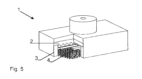
[0015] - Figure 5 shows a side view of the example radiant burner of figure 4,
also
with cut out for better view of the build up of the radiant burner.
[0016] - Figure 6 shows an alternative example embodiment of the present
invention.
[0017] - Figure 7 shows a side view of the example radiant burner of figure 6.
Mode(s) for Carrying Out the Invention
[0018] Example embodiments of the present invention will now be described with
reference to Figures 1 to 7.
[0019] Figures 1 to 3 show cross sections of example embodiments of radiant
burner plates which might be used in the present invention. Figure 1
shows two levels of burner surface of the radiant burner plate 2, figures 2
and 3 show three levels of burner surface, in two alternative forms.
[0020] Figures 4 and 5 show an example embodiment of the present invention.
The first radiant screen 4 is a highly heat resisting metal grid fabricated
from highly heat resistant steel grades, such as high level stainless steel
grades like Kanthal APM or APMT, different grades of FeCrAI alloy
designed for high temperature corrosion, Chrome/Nickel steel grades like
Avesta 253 MA, 153 MA, Inconel 601, Incoloy 800HT, Incoloy MA956.
The second radiant screen 3 is made of a highly heat resisting ceramic
material, in this example aluminium or zirconium oxide, aluminium titanate,
silicon oxide, corundum or mullite, silicon carbide, silicon nitride or metal
infiltrated ceramics, such as silicon-infiltrated silicon carbide with a
silicon
infiltration grade of 5 to 50 % or even more. Alternatively, the radiant
screens can also be fabricated from heat-resistant materials of other
nature such as e.g. materials which contain more than 50% by weight of a
CA 02726927 2010-12-03
WO 2010/003904 PCT/EP2009/058429
6
metal silicide, such as molybdenum disilicide (MoSi2) or tungsten disilicide
(WSi2). The radiant burner plate 2 is made of a two level burner surface,
ceramic tile made of cordorite or alternate thermodynamically suited
ceramics as mentioned above.
[0021] Figures 6 and 7 show an alternative example embodiment of the present
invention. The first and second radiant screens are made of highly heat
resisting material, in this example a ceramic like aluminium or zirconium
oxide, aluminium titanate, silicon oxide, corundum or mullite, silicon
carbide, silicon nitride or metal infiltrated ceramics, such as silicon-
infiltrated silicon carbide with a silicon infiltration grade of 5 to 50 % or
even more. Alternatively, the radiant screens can also be fabricated from
heat-resistant materials of other nature such as e.g. materials which
contain more than 50% by weight of a metal silicide, such as molybdenum
disilicide (MoSi2) or tungsten disilicide (WSi2). In this example this first
and second radiant screens are arranged in directions which are 90 with
respect to one another. The radiant burner plate 2 is made of a two level
burner surface, ceramic tile made of cordierite.
[0022] Thus there has been described a new radiant burner 1 possessing great
flexibility of use and which is capable of reaching temperatures of about
1300 C with a considerable radiation factor increase of about 10 %
compared to existing technology.
[0023] Because of their possible use at very high temperatures e.g. 1300 C and
higher, their high energy efficiency and their long service life, the radiant
burner of the present invention are particularly suitable for drying web
materials at high web speeds. One preferred area of application is the
drying of moving paper webs.
[0024] The new improved radiant burner comprises a body defining a premixing
chamber and a combustion chamber. The premixing chamber is
separated from the combustion chamber by at least one radiant burner
plate which has multiple levels of burner surface. The combustion
chamber is further limited by a first radiant screen. The radiant burner
further comprises a second radiant screen in the combustion chamber.
CA 02726927 2010-12-03
WO 2010/003904 PCT/EP2009/058429
7
The second radiant screen is spaced from, but near the radiant burner
plate(s), such that this second radiant screen acts as an extended burner
surface and also heats up said at least one radiant burner plate when in
use.