Note: Descriptions are shown in the official language in which they were submitted.
CA 02727225 2011-01-10
FISH LURE
Technical Field
[0001] This invention relates to lures for use in fishing and related methods.
Background
[0002] Fishing is an activity enjoyed by a wide range of people. Fishing is
pursued
for enjoyment, livelihood, and sustenance. A successful lure attracts fish to
attack
the lure. Fish respond to factors such as the appearance of a lure, the way
the lure
moves through the water, and vibrations in the water made by the passage of
the
lure. The tastes of fish are different from time to time and place to place.
People
who fish typically have a wide assortment of lures. It is a challenge to
select a lure
that will attract fish at the time and in the place where they are fishing.
Summary
[0003] Further aspects of the invention and features of a range of example
embodiments are discussed below and illustrated in the accompanying drawings.
Brief Description of Drawings
[0004] Exemplary embodiments are illustrated in referenced figures of the
drawings. The embodiments and figures disclosed herein are intended to be
illustrative and not restrictive.
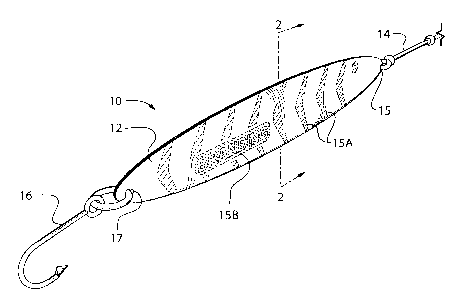
[0005] Figure 1 is a perspective view of a fish lure according to an example
embodiment of the invention.
[0006] Figure 2 is a cross section of the lure of Figure 1 in the plane 2-2.
[0007] Figures 2A through 2B illustrate an example manner of use of the fish
lure.
[0008] Figure 3 illustrates a method for forming the fish lure to have a
desired
configuration.
[0009] Figure 4 is a flowchart illustrating a method for making a lure of the
type
shown in Figure 1.
[0010] Figures 4A through 4G illustrate intermediate stages in an example
method
for manufacturing a fish lure like that shown in Figure 1.
[0011] Figures 5A through 5E illustrate various alternative ways in which a
fish
lure as shown in Figure 1 may be shaped by a user.
CA 02727225 2011-01-10
-2-
[0012] Figure 6 is a perspective view of a fish lure according to an example
embodiment of the invention.
Description
[0013] Throughout the following description specific details are set forth in
order to
provide a more thorough understanding to persons skilled in the art. However,
well
known elements may not have been shown or described in detail to avoid
unnecessarily obscuring the disclosure. Accordingly, the description and
drawings
are to be regarded in an illustrative, rather than a restrictive, sense.
[0014] Figure 1 shows a fish lure 10 according to an example embodiment. Fish
lure 10 has a flattened body 12. A leader 14 is attached at an attachment
point 15 at
one end of body 12 and a hook 16 is attached at an attachment point 17 at
another
end of body 12.
[0015] In the illustrated embodiment, body 12 comprises a central sheet 18
(see
Figure 2) coated on each face with a layer of a material 19 which gives body
12
some thickness. In an example embodiment, body 12 has a thickness of
approximately 1/16 to 3/16 inches, a length of about 2 to 4 inches, and a
height of
about 1 to 2 inches.
[0016] In some embodiments, sheet 18 has indicia marked on it and material 19
is
transparent so that those indicia can be seen when body 12 is observed. In the
illustrated embodiment the indicia includes patterning 15A and branding 15B.
In
some embodiments, each face of sheet 18 comprises a shiny material such as a
hologram material, a metal foil, an embossed foil, a laser-engraved aluminized
surface, or the like. Fish tend to be attracted to shiny lures.
[0017] As shown in Figures 2A and 2B, material 19 has the property that it
becomes
malleable at a temperature somewhat above normal room temperature but holds
its
shape at lower temperatures such as the temperature of water in which the lure
will
be used for fishing. A user can warm body 12 for example by placing body 12 in
hot or warm water; heating body 12 in the sun; or the like, until body 12
becomes
malleable. Then, as illustrated in Figure 2B, the user can shape body 12 to
have a
desired configuration. For example, the user may make one or more bends in
body
12. The user can then let body 12 cool so that it retains the configuration
that has
been imparted to it. The user can then use lure 10 for fishing.
CA 02727225 2011-01-10
.10
-3-
[0018] Body 12 may be molded and shaped in a wide range of ways that change
its
appearance as well as change the way it moves through the water and the
vibrations
it makes while moving through the water.
[0019] A method 20 for forming body 12 to provide a desired shape is
illustrated in
Figure 3. Method 20 which comprises warming the body 12 of a lure 10 in block
21, forming the body 12 into a desired configuration in block 22, and allowing
the
body to cool so as to retain the imparted configuration in block 23. The lure
10
may subsequently be used for fishing in the usual way. In some embodiments,
block 21 comprises heating body 12 to a temperature of 100 C or lower.
[0020] Figure 4 illustrates a method 30 for making a lure according to an
example
embodiment. Method 30 begins at block 31 with providing labels which have the
overall shape of body 12. The labels may comprise self-adhesive labels having
an
adhesive layer protected by a release sheet. Front surfaces of the adhesive
labels
may optionally be of a shiny material such as a foil or the like.
[0021] In block 32, indicia are applied on the front surfaces of the labels.
Figure
4A shows example self-adhesive labels 41 bearing various indicia.
[0022] Block 32 may be performed with a suitable printer such as a laser
printer, an
inkjet printer, a commercial printing press, or the like. The indica may, for
example, comprise indicia that resemble a pattern of spots or other patterns
resembling the skin of a fish, indicia having an appearance thought to appeal
to fish
(or to appeal to fisherman as being the sort of appearance that would appeal
to fish).
Applying the indicia may also comprise adhering objects, stickers, or the like
to the
labels.
[0023] The indicia may optionally include a branding such as the name or logo
of a
manufacturer or sponsor. The branding may include typed text or the like (for
example, lure 12 may be made as a promotional item for a fishing lodge or
other
business in which case the name and contact information for the fishing lodge
or
other business may be printed onto the front surface of one or both labels in
block
32).
[0024] In block 33, a flowable material having suitable characteristics to
form layers
19 is applied, for example, by pouring, onto each of the labels until the
material
reaches the edge of the labels. The flowable material is allowed to form a
domed
shape under its surface tension. In block 33 the entire surface of both labels
is
preferably covered with the flowable material. The flowable material may, for
CA 02727225 2011-01-10
-4-
example, comprise a two-part self-leveling epoxy. In some embodiments, the
epoxy
is an epoxy which is transparent, when cured. Figure 4B shows labels 41 after
layers 42 of uncured flowable material have been applied. One material that
has
been found to be satisfactory is a clear self-leveling two-part epoxy resin
"bar top
coating" having a resin component having a viscosity of 900 cps and a specific
gravity of 1.15 and a hardener component having a viscosity of 100 cps and a
specific gravity of 0.95. The hardener may be mixed with the resin in a ratio
of 2
parts resin to one part hardener. The cured material has a heat deflection
temperature of 120 F. A product having these characteristics is available as
MIRRORCOATTM self-leveling bar top coating from System Three Resins, Inc. of
Auburn Washington USA.
[0025] In block 34, the epoxy is allowed to cure. Figure 4C shows labels 41
and
layers 43 of cured material. The cured material is transparent so that indicia
33 can
be seen through layers 43. In its cured form, the epoxy has a transition
temperature
or a transition range of temperatures above which it is malleable but below
which it
retains a form imparted to it when above the transition temperature. The
transition
temperature is preferably low enough that the lure can be handled with bare
hands
while body 12 is above the transition temperature. In some embodiments the
transition temperature is below 90 C and above 35 C.
[0026] In block 35, the labels are adhered back-to-back. Block 35 may, for
example, comprise removing release sheets from the backs of the labels
aligning the
adhesive surfaces of the labels and sticking the two labels together to form
body 12.
This is illustrated in Figure 4D which shows release sheets 45 being removed
to
reveal adhesive 46. Figure 4E shows labels 41 being brought together in an
aligned
manner so that adhesive surfaces 46 band to one another. In other embodiments
labels are adhered by applying a suitable adhesive to one or both labels and
then
adhering the labels to one another or applying a double-sided tape between the
labels
or the like.
[0027] In block 36, holes or other attachment points are formed to allow a
leader
and hook to be attached to body 12. Figures 4F and 4G show holes 47A and 47B
formed at either end of the lure body.
[0028] Providing a sheet 18 is optional. In alternative embodiments, a body 12
can
be made by shaping or forming the body 12 directly from a sheet of material
that
becomes malleable at warmer temperatures, as described above. For example,
body
CA 02727225 2011-01-10
-5-
12 may comprise a sheet of plastic of a type that becomes malleable at a
temperature
above a transition temperature in the range of about 30 C to 100 C.
[0029] Where a sheet 18 is provided, it is not necessary that the sheet be
made of
back-to-back self-adhesive labels. In some alternative embodiments, sheet 18
comprises sheets of paper, cardboard, plastic, or other suitable material and
the
sheets 18 are attached to one another through use of a suitable adhesive,
plastic
welding, or the like. Additionally, sheet 18 may comprise a single sheet of
material
in which a layer 19 on one side is applied first and after that first layer 19
has
cured, another layer 18 may be applied on the opposing side of the body.
[0030] Figures 5A through 5E illustrate some example ways in which a lure body
as
described herein may be formed. Figure 5A shows a lure body formed to have a
simple curve. Figure 5B shows a lure body formed to have an undulating curve
which curves first one way and then another way. Figure 5C shows a lure body
which has been formed to provide a spoon-shape, on a portion thereof. Figure
5D
shows a lure body which has been formed to have a twist. Figure 5E shows a
lure
body which has been formed to provide a relatively sharp bend.
[0031] Figure 6 illustrates a fish lure 50 according to an example embodiment
of the
invention. Fish lure 50 has a flattened body 52. Body 52 may be of
construction
similar to body 12 of lure 10 illustrated in Figure 1, as described herein.
Body 52
has a first attachment point 55 at one end of body 52 and a second attachment
57 at
another end of body 52.
[0032] In the illustrated embodiment, attachment point 55 comprises closely
spaced
holes 55A and 55B, and attachment point 57 comprises a single hole 57A. A line
54 threaded through holes 55A, 55B and 57A is attached at one end to a hook
56.
Line 54 may be attached to hook 56 by tying, for example.
[0033] A wide number of alternatives are possible in both the methods for
making a
lure and the construction of the lure. Some examples are:
= Body 12 may have a wide range of shapes that are different from the shape
illustrated. It is not mandatory that body 12 have a fish shape.
= It is not necessary that body 12 have a single sharply defined transition
temperature. The transition temperature may comprise a range of
temperatures over which body 12 becomes malleable.
CA 02727225 2011-01-10
-6-
[0034] While a number of exemplary aspects and embodiments have been discussed
above, those of skill in the art will recognize certain modifications,
permutations,
additions and sub-combinations thereof. It is therefore intended that the
following
appended claims and claims hereafter introduced are interpreted to include all
such
modifications, permutations, additions and sub-combinations as are within
their true
spirit and scope.