Note: Descriptions are shown in the official language in which they were submitted.
CA 02727358 2011-01-10
RING BINDER MECHANISM HAVING DUAL TIME
BUFFER ACTUATOR
FIELD OF INVENTION
[001] This invention relates to a ring binder
mechanism for retaining loose-leaf pages, and in particular
to an improved ring binder mechanism for opening and
closing ring members and for locking closed ring members
together.
BACKGROUND OF THE INVENTION
[002] Ring binder mechanisms retain loose-leaf pages
on rings. Ring binder mechanisms can be used in notebooks,
files, briefcases, clipboards and other similar objects to
give the object a loose-leaf page retaining function. A
conventional ring binder mechanism has rings formed by ring
members that are selectively moveable to open the rings to
add and/or remove loose leaf pages and close the rings to
retain loose-leaf pages on the rings. The ring members are
commonly mounted on adjoining hinge plates supported by a
housing for pivoting movement between open and closed
positions. The undeformed housing is slightly narrower than
the combined width of the hinge plates such that the
housing applies a spring force that biases the ring members
against movement toward the open position when they are in
the closed position. If this spring force is strong, there
is a risk that a user could be injured by getting a finger
pinched between the ring members as the housing causes them
to snap shut during closing. Thus, it is desirable to
design the housing so it exerts a relatively light spring
force on the ring members to reduce the risk of injury to
users.
[003] However, the absence of a strong biasing force
holding the ring members in the closed position increases
1
CA 02727358 2011-01-10
the risk that the rings will inadvertently open (e.g., if
the ring mechanism is accidentally dropped) and fail to
retain loose-leaf pages. One way to reduce the risk the
rings will inadvertently open is to provide a locking
system that blocks pivoting movement of the ring members
from the closed position to the open position. It is
desirable for the locking system to automatically lock the
rings closed when the rings are moved to the closed
position. It is also desirable to be able to unlock and
open the rings in a single step to make the ring mechanism
convenient to use.
[004] United States Pub. App. No. 20080124166, which
is commonly owned with the present application, discloses a
ring mechanism having an actuator operable to engage the
hinge plates and move the rings between the open and closed
positions. The mechanism also includes a travel bar having
a locking element connected to the actuator so the actuator
can move the travel bar and locking element between a
locking and unlocking position as the actuator moves the
rings between the open and closed position.
[005] The actuator in the '166 application is
designed to deform during opening and closing to sequence
movement of the travel bar (and its locking element) with
movement of the hinge plates. During use of the actuator to
open the rings, the actuator deforms to delay movement of
the hinge plates from movement of the travel bar and
locking element so the travel bar and locking element can
be moved away from the locking position before the actuator
moves the hinge plates to open the rings. During use of the
actuator to close the rings, the actuator deforms to delay
movement of the travel bar and locking element from
movement of the hinge plates so the hinge plates can move
to the closed position before the actuator moves the
locking element into the locking position. This allows a
2
CA 02727358 2011-01-10
user to unlock and open the rings in a single movement of
the actuator. It also allows a user to close and lock the
rings in a single movement of the actuator.
[006] Figures 15-18 of the present application
illustrate the closing action of the actuator in the '166
application. As illustrated, the travel bar 45 is connected
to the actuator 15 by an intermediate connector 67 having
ends 68a, 68b that are inserted into an opening in a
flexible arm 38 (Fig. 15) on the actuator 15. Figure 17
shows the configuration of the actuator 15 when the rings
are open and Fig. 18 shows the configuration of the
actuator during movement of the actuator to close the
rings. As illustrated in Fig. 18, the flexible arm 38
deforms during closing by bending in a direction (e.g.,
clockwise in Fig. 18) relative to the rest of the actuator
that is opposite the direction (e.g., counterclockwise in
Fig. 18) in which the actuator rotates during use of the
actuator to close the rings. This deformation of the
flexible arm 18 delays movement of the travel bar 45 from
movement of the hinge plates during closing.
SUMMARY OF THE INVENTION
[007] One aspect of the invention is a ring mechanism
for holding loose-leaf pages. The mechanism has an elongate
housing. The mechanism also has rings for holding the
loose-leaf pages. Each ring includes a first ring member
and a second ring member. The first ring members are
movable relative to the housing and uhe second ring members
between a closed position and an open position. In the
closed position the first and second ring members form a
substantially continuous, closed loop for allowing loose-
leaf pages retained by the rings to be moved along the
rings from one ring member to the other. In the open
position the first and second ring members form a
3
CA 02727358 2011-01-10
discontinuous, open loop for adding or removing loose-leaf
pages from the rings. The mechanism has first and second
hinge plates supported by the housing for pivoting motion
relative to the housing. The first ring members are mounted
on the first hinge plate and moveable with the pivoting
motion of the first hinge plate between the closed and open
positions. An actuator is moveable relative to the housing
to cause the pivoting motion of the hinge plates. The
actuator is moveable between a first position in which the
ring members are in the closed position and a second
position in which the ring members are in the open
position. The actuator has: (i) a body; (ii) a closing arm
extending from the body and positioned to pivot the hinge
plates and move the rings to the closed position when the
actuator moves from the second position to the first
position; and (iii) an opening arm extending from the body
and positioned to pivot the hinge plates and move the rings
to the open position when the actuator moves from the first
position to the second position. The mechanism also has a
travel bar including a locking element. The travel bar is
moveable between a locked position in which the locking
element blocks pivoting movement of the hinge plates to
move the rings from the closed position to the open
position and an unlocked position in which the locking
element permits pivoting movement of the hinge plates to
open the rings. The actuator has a flexible arm positioned
to push the travel bar toward the locked position when the
actuator moves from the second position to the first
position. At least a portion of the flexible arm is adapted
to deform when the actuator is moved from the second
position to the first position in a manner that includes
rotation of the portion of the flexible arm in a first
direction relative to the body of the actuator. Movement of
the actuator from the second position to the first position
4
CA 02727358 2011-01-10
also includes rotation of the actuator in this first
direction relative to the housing.
[008] Another aspect of the invention is a ring
mechanism for holding loose-leaf pages. The mechanism has
elongate housing and rings for holding the loose-leaf
pages. Each ring includes a first ring member and a second
ring member. The first ring members are movable relative to
the housing and the second ring members between a closed
position and an open position. In the closed position the
first and second ring members form a substantially
continuous, closed loop for allowing loose-leaf pages
retained by the rings to be moved along the rings from one
ring member to the other. In the open position the first
and second ring members form a discontinuous, open loop for
adding or removing loose-leaf pages from the rings. The
mechanism has first and second hinge plates supported by
the housing for pivoting motion relative to the housing.
The first ring members are mounted on the first hinge plate
and moveable with the pivoting motion of the first hinge
plate between the closed and open positions. An actuator is
pivotable relative to the housing about a pivot axis to
cause the pivoting motion of the hinge plates. The actuator
is pivotable between a first position in which the ring
members are in the closed position and a second position in
which the ring members are in the open position. The
actuator has: (i) a body; (ii) a closing arm extending
from the body and positioned to pivot the hinge plates and
move the rings to the closed position when the actuator
moves from the second position to the first position; (iii)
an opening arm extending from the body and positioned to
pivot the hinge plates and move the rings to the open
position when the actuator moves from the first position to
the second position; (iv) a handle extending from the body
for use by a user to pivot the actuator between the first
CA 02727358 2016-01-11
64725-1156
and second positions; and (v) a generally channel shaped space
in the actuator. The mechanism includes a travel bar having a
locking element. The travel bar is moveable by the pivoting
movement of the actuator between a locked position in which the
locking element blocks pivoting movement of the hinge plates to
move the rings from the closed position to the open position
and an unlocked position in which the locking element permits
pivoting movement of the hinge plates to open the rings. The
travel bar has an end that is captured by the actuator in the
space. The travel bar and actuator are adapted so the end of
the travel bar can be snapped into said space during assembly
of the ring mechanism by moving the travel bar relative to the
actuator in a direction that is generally perpendicular to the
pivot axis of the actuator.
[008a] Another aspect of the invention is a ring mechanism
for holding loose-leaf pages, the mechanism comprising: an
elongate housing; rings for holding the loose-leaf pages, each
ring including a first ring member and a second ring member,
the first ring members being movable relative to the housing
and the second ring members between a closed position and an
open position, in the closed position the first and second ring
members forming a substantially continuous, closed loop for
allowing loose-leaf pages retained by the rings to be moved
along the rings from one ring member to the other, and in the
open position the first and second ring members forming a
discontinuous, open loop for adding or removing loose-leaf
pages from the rings; first and second hinge plates supported
by the housing for pivoting motion relative to the housing,
said first ring members being mounted on the first hinge plate
and moveable with the pivoting motion of the first hinge plate
6
CA 02727358 2016-01-11
64725-1156
between the closed and open positions; an actuator moveable
relative to the housing to cause the pivoting motion of the
hinge plates, the actuator being moveable between a first
position in which the ring members are in the closed position
and a second position in which the ring members are in the open
position, the actuator comprising (i) a body; (ii) a closing
arm extending from the body and positioned to pivot the hinge
plates and move the rings to the closed position when the
actuator moves from the second position to the first position;
and (iii) an opening arm extending from the body and positioned
to pivot the hinge plates and move the rings to the open
position when the actuator moves from the first position to the
second position; and a travel bar comprising a locking element,
the travel bar being moveable between a locked position in
which the locking element blocks pivoting movement of the hinge
plates to move the rings from the closed position to the open
position and an unlocked position in which the locking element
permits pivoting movement of the hinge plates to open the
rings, the actuator further comprising a flexible arm
positioned to push the travel bar toward the locked position
when the actuator moves from the second position to the first
position, at least a portion of the flexible arm being adapted
to deform when the actuator is moved from the second position
to the first position, said deformation resulting in rotation
of said portion of the flexible arm relative to the body of the
actuator in a first direction, wherein movement of the actuator
from the second position to the first position includes
rotation of the actuator relative to the housing in said first
direction.
6a
CA 02727358 2016-01-11
64725-1156
[008b] Another aspect of the invention is a ring mechanism
for holding loose-leaf pages, the mechanism comprising: an
elongate housing; rings for holding the loose-leaf pages, each
ring including a first ring member and a second ring member,
the first ring members being movable relative to the housing
and the second ring members between a closed position and an
open position, in the closed position the first and second ring
members forming a substantially continuous, closed loop for
allowing loose-leaf pages retained by the rings to be moved
along the rings from one ring member to the other, and in the
open position the first and second ring members forming a
discontinuous, open loop for adding or removing loose-leaf
pages from the rings; first and second hinge plates supported
by the housing for pivoting motion relative to the housing,
said first ring members being mounted on the first hinge plate
and moveable with the pivoting motion of the first hinge plate
between the closed and open positions; an actuator pivotable
relative to the housing about a pivot axis to cause the
pivoting motion of the hinge plates, the actuator being
pivotable between a first position in which the ring members
are in the closed position and a second position in which the
ring members are in the open position, the actuator comprising
(i) a body; (ii) a closing arm extending from the body and
positioned to pivot the hinge plates and move the rings to the
closed position when the actuator moves from the second
position to the first position; (iii) an opening arm extending
from the body and positioned to pivot the hinge plates and move
the rings to the open position when the actuator moves from the
first position to the second position; (iv) a handle extending
from the body for use by a user to pivot the actuator between
the first and second positions; and (v) a generally channel
6b
CA 02727358 2016-01-11
64725-1156
shaped space in the actuator, the channel shaped space opening
radially outward of the actuator from the pivot axis; and a
travel bar comprising a locking element, the travel bar being
moveable by the pivoting movement of the actuator between a
locked position in which the locking element blocks pivoting
movement of the hinge plates to move the rings from the closed
position to the open position and an unlocked position in which
the locking element permits pivoting movement of the hinge
plates to open the rings, wherein the travel bar has an end
that is captured by the actuator in the channel shaped space,
the travel bar and actuator being adapted so the end of the
travel bar can be snapped into said channel shaped space during
assembly of the ring mechanism by moving the travel bar
relative to the actuator into said channel shaped space in a
direction that is perpendicular to said pivot axis of the
actuator as the end of the travel bar is received in said
channel shaped space; and wherein the end of the travel bar
comprises opposing ears extending inward toward one another,
the actuator further comprising a rib extending from the
closing arm to the handle, the rib being positioned between the
opposing ears at the end of the travel bar.
[008c] Another aspect of the invention is a ring mechanism
for holding loose-leaf pages, the mechanism comprising: an
elongate housing; rings for holding the loose-leaf pages, each
ring including a first ring member and a second ring member,
the first ring members being movable relative to the housing
and the second ring members between a closed position and an
open position, in the closed position the first and second ring
members forming a substantially continuous, closed loop for
allowing loose-leaf pages retained by the rings to be moved
6c
CA 02727358 2016-01-11
,64725-1156
along the rings from one ring member to the other, and in the
open position the first and second ring members forming a
discontinuous, open loop for adding or removing loose-leaf
pages from the rings; first and second hinge plates supported
by the housing for pivoting motion relative to the housing,
said first ring members being mounted on the first hinge plate
and moveable with the pivoting motion of the first hinge plate
between the closed and open positions; an actuator pivotable
relative to the housing about a pivot axis to cause the
pivoting motion of the hinge plates, the actuator being
pivotable between a first position in which the ring members
are in the closed position and a second position in which the
ring members are in the open position, the actuator comprising
(i) a body; (ii) a closing arm extending from the body and
positioned to pivot the hinge plates and move the rings to the
closed position when the actuator moves from the second
position to the first position; (iii) an opening arm extending
from the body and positioned to pivot the hinge plates and move
the rings to the open position when the actuator moves from the
first position to the second position; (iv) a handle extending
from the body for use by a user to pivot the actuator between
the first and second positions; and (v) a generally channel
shaped space in the actuator, the channel shaped space opening
radially outward of the actuator from the pivot axis; and a
travel bar comprising a locking element, the travel bar being
moveable by the pivoting movement of the actuator between a
locked position in which the locking element blocks pivoting
movement of the hinge plates to move the rings from the closed
position to the open position and an unlocked position in which
the locking element permits pivoting movement of the hinge
plates to open the rings, wherein the travel bar has an end
6d
CA 02727358 2016-01-11
64725-1156
that is captured by the actuator in the channel shaped space,
the travel bar and actuator being adapted so the end of the
travel bar can be snapped into said channel shaped space during
assembly of the ring mechanism by moving the travel bar
relative to the actuator into said space in a direction that is
transverse to said pivot axis of the actuator as the end of the
travel bar is received in said channel shaped space.
[009] Other features of the invention will be in part
apparent and in part pointed out hereinafter.
BRIEF DESCRIPTION OF THE DRAWINGS
[0010] FIG. 1 is a perspective of a notebook and a ring
binder mechanism;
[0011] FIG. 2 is an exploded perspective of the ring
mechanism;
[0012] FIG. 3 is an enlarged fragmentary perspective the
mechanism in which a portion of the housing is broken away and
some features as illustrated in cross section to show internal
features of the mechanism;
[0013] FIG. 4 is an enlarged perspective of an actuator and
an end of a travel bar of the ring mechanism prior to their
assembly;
[0014] FIGS. 5A-5C are enlarged side views of the actuator
and end of the travel bar illustrating an assembly sequence
thereof;
6e
CA 02727358 2011-01-10
[0015] FIGS. 6A-6E are enlarged fragmentary side
elevations the ring mechanism in longitudinal cross section
illustrating a sequence in which the actuator is used to
open and then close the rings;
[0016] FIGS. 7A-70 are perspectives from a vantage
point in which the bottom of the ring mechanism is visible
illustrating a sequence in which the actuator is used to
open the rings;
[0017] FIG. 8 is an exploded perspective of a second
embodiment of a ring mechanism of the present invention;
[0018] FIG. 9 is a perspective showing a wire
connector connecting a travel bar and actuator of the ring
mechanism illustrated in Fig. 8;
[0019] FIG. 10 is an exploded perspective of a third
embodiment of a ring mechanism of the present invention;
[0020] FIG. 11 is an enlarged fragmenatary perspective
of the ring mechanism illustrated in Fig. 11 in which some
parts are illustrated in longitudinal cross section to show
internal features;
[0021] FIG. 12 is an enlarged perspective of an
actuator and an end of a travel bar of the ring mechanism
illustrated in Figs. 10 and 11 just prior to connection
therebetween;
[0022] FIG. 13 is an enlarged top plan view of the
actuator and end of the travel bar illustrated in Fig. 12
connected together;
[0023] FIGS. 14A-14E illustrated a sequence in which
the actuator of the ring mechanism illustrated in Figs. 10-
13 is used to open and close the rings; and
[0024] FIGS. 15-18 illustrate a prior art ring
mechanism.
[0025] Corresponding reference numbers indicate
corresponding parts throughout the views of the drawings.
7
CA 02727358 2011-01-10
DETAILED DESCRIPTION
[0026] Referring to the drawings, Figs. 1-2 show a
first embodiment of a ring binder mechanism of the
invention, generally indicated at 101. In Fig. 1, the
mechanism 101 is mounted on a notebook cover 103.
Specifically, the mechanism 101 is mounted adjacent the
spine 105 of the notebook cover 103. The spine 105 extends
between front and back covers 107, 109 that are hingedly
attached to the spine 105. The front and back covers 107,
109 are moveable to selectively cover or expose loose-leaf
pages (not shown) retained by the mechanism 101. Ring
binder mechanisms mounted on a notebook cover in other ways
(e.g., on the spine) or on substrates other than a notebook
cover (e.g., a file, a briefcase, etc.) do not depart from
the scope of this invention.
[0027] As shown in Figs. 1 and 2, the mechanism 101
includes an elongate housing 111 supporting a plurality of
rings (each of which is designated generally 113). The
housing 111 has a generally rectangular perimeter. The
housing 111 also has a raised flat central plateau 117 and
sides 119 extending down and laterally outward from
opposite sides of the plateau. The plateau 117 and sides
119 give the housing a roughly arch-shaped cross sectional
shape. The flatness of the plateau 117 and sides 119 make
the arch-shaped cross sectional shape of the housing 111
illustrated in Figs. 1 and 2 a segmented and angular arch
shape. However, it is understood that the sides and central
top portion of the housing can be more smoothly curved
within the scope of the invention. A first longitudinal end
121 of the housing 111 is generally open while a second,
opposite longitudinal end 123 is generally closed. Bent
under rims 125 extend lengthwise along the outer edge
margins of the sides 119 of the housing 111. Mechanisms
having housings shaped differently than the housing 111
8
CA 02727358 2011-01-10
illustrated in the drawings, including irregular shapes, or
housings that are integral with a file or notebook do not
depart from the scope of this invention.
[0028] The rings 113 are operable to retain loose-leaf
pages on the ring mechanism 101 in the notebook 103. The
ring mechanism 101 illustrated in the drawings has three
rings 113. However, the number of rings can vary within the
scope of the invention. The rings 113 shown in the drawings
are substantially identical to one another and are each
generally circular in shape. As shown in Figs. 1 and 2, the
rings 113 each include two generally semi-circular ring
members 133 (sometimes referred to and designated 133a and
133b to refer to a particular one of the ring members in a
pair) formed from a conventional, cylindrical rod of a
suitable material (e.g., steel). Ring binder mechanisms
with ring members formed of different material or having
different cross-sectional shapes (e.g., oval cross
sectional shapes) do not depart from the scope of this
invention. Also, the rings do not have to be substantially
circular. Further, one of the ring members can have a
different shape from the other, such as is the case with D-
shaped rings and other asymmetric rings known in the art.
[0029] One of the ring members 133a of each ring 113
is moveable relative to the housing 111 and the opposing
ring member 133b between a closed position and an open
position. In the ring mechanism 101 shown in the drawings,
the two ring members 133a, 133b each move in a
substantially similar way relative to housing 111 to open
and close the rings 113, but this is not necessary to
practice the invention. For example, one of the ring
members of each ring could be fixed to the housing within
the scope of the invention. In the closed position (Fig. 1)
the ring members 133 form a substantially continuous,
closed loop for allowing loose-leaf pages retained by the
9
CA 02727358 2011-01-10
rings 113 to be moved along the rings from one ring member
to the other. In the open position (Fig. 7C) the ring
members 133 form a discontinuous, open loop for adding or
removing loose-leaf pages from the rings.
[0030] The ring mechanism 101 includes two
substantially identical hinge plates 127 supporting the
ring members 133. The hinge plates 127 are each generally
elongate, flat, and rectangular in shape and are each
somewhat shorter in length than the housing 111. The hinge
plates 127 are interconnected In parallel arrangement along
their inner longitudinal edge margins (as illustrated in
Figs. 7A-7C), forming a central hinge 145 having a pivot
axis. This is suitably done in a conventional manner known
in the art. The outer longitudinal edge margins of the
hinge plates 127 are received in the grooves (Figs. 3 and
7A-7c) formed by the bent under rims 125 of the housing
111, which thereby supports the hinge plates for pivoting
within the housing. As shown in Fig. 2, the ring members
133a, 133b are each mounted in generally opposed fashion on
upper surfaces of respective ones of the hinge plates 127
(which are sometimes designated 127a and 127b to correspond
with the designation of the respective ring member). The
ring members 133 extend through respective openings 155
along the sides 119 of the housing 111 so that the free
ends of the ring members engage one another above the
housing when the rings 113 are closed. The ring members
133 are rigidly connected to the hinge plates 127, as is
known in the art, and move with the hinge plates when they
pivot. In the ring binder mechanism 101 illustrated in the
drawings, both ring members 133 of each ring 113 are
mounted so they extend from the upper surfaces of the hinge
plates 127. However, a mechanism in which one or more ring
members are mounted so they extend from a lower surface of
the hinge plate (e.g., as disclosed in commonly owned U.S.
CA 02727358 2011-01-10
Pub. Pat. App. No. 20080008519) is also within the scope of
the invention.
[0031] The hinge plates 127 can be pivoted downward
and upward on the central hinge 145 relative to the housing
111 to move the ring members 133 mounted thereon between
the closed position and the open position. The ring members
133 close when the hinge plates 127 pivot downward (i.e.,
the central hinge 145 moves away from the housing 111). The
ring members 133 open when the hinge plates 127 pivot
upward (i.e., the central hinge axis 145 moves toward the
housing 111). The hinge plates 127 are together wider than
the spacing between the bent under rims 125 of the housing
111 when in a co-planar position (180 degrees).
Consequently, as they pivot through the co-planar position,
the hinge plates deform the housing and create a spring
force in the housing. The housing spring force biases the
hinge plates 127 to pivot away from the co-planar position,
either downward or upward. Thus, the housing spring force
biases the rings 113 to remain closed when they are in the
closed position and biases the rings to remain open when
they are in the open position.
[0032] An actuator 115 is moveable relative to the
housing 111 by a user to cause the pivoting motion of the
hinge plates 127 against the spring force from the housing
111 to open and close the rings 113. The actuator 115 is
rotatable between a first position (Fig. 6A) in which the
ring members 133 are in the closed position and a second
position (Fig. 60) in which the ring members are in the
open position.
[0033] In the illustrated embodiment, the actuator 115
is mounted for pivoting movement relative to the housing
between the open and closed positions on a lever mount 171
(Figs. 1 and 2) formed separately from the housing 111 and
secured to the housing (e.g., by one or mcre rivets 173 or
11
CA 02727358 2011-01-10
other suitable fasteners). The lever mount 171 includes a
plate 175 positioned on top of the housing plateau 117 at
the open end 121 of the housing 111. The lever mount 171
also has arms 177 extending from opposite sides of the
plate 175 into the housing 111 through slots 179 at the end
121 of the housing. The actuator 115 is pivotally connected
to the lever mount by a pivot pin 181 extending through the
actuator and retained by the arms of the lever mount. Thus,
the actuator 115 is pivotal about a pivot axis coincident
with the pin 181. The lever mount 171 does not extend
longitudinally beyond the open end 121 of the housing 111.
Also, only a relatively minor portion of the actuator 115
extends longitudinally beyond the open end 121 of the
housing 111 when the rings are closed. Other ways of
mounting the actuator, including directly to the housing
without a separate lever mount do not depart from the scope
of the invention.
[0034] Referring now to Figs. 3, 4, and 6A-6E, the
actuator 115 has a body 201 and a closing arm 203 extending
from the body. The closing arm 203 is positioned to pivot
the hinge plates 127 and move the rings 113 to the closed
position when the actuator is moved from the open position
to the closed position. The actuator 115 also has an
opening arm 205 extending from the body 201 and positioned
to pivot the hinge plates 127 and move the rings 113 to the
open position when the actuator is moved from the closed
position to the open position. As seen in Figs. 3 and 4,
the closing and opening arms 203, 205 form a channel 207 in
which the ends of the hinge plates 127 are received. A
handle 211 extends from the body 201 of the actuator 115 to
facilitate movement of the actuator by a user between the
open and closed position. The handle of the actuator can
have many different shapes within the scope of the
Invention.
12
CA 02727358 2011-01-10
[0035] The ends of the hinge plates 127 are received
in the channel 207 sc the closing arm 203 is above the ends
of the hinge plates and the opening arm 205 is below the
ends of the hinge plates. Each of the hinge plates has a
relatively narrow finger 141 (Fig. 2) extending
longitudinally toward the open end 121 of the housing. The
fingers 141 are each narrower in width than the respective
hinge plates 127 and are positioned so their inner
longitudinal edges are generally aligned with the inner
longitudinal edges and central hinge 145 of the hinge
plates. When the actuator 115 is moved from the closed
position to the open position, the opening arm 205 applies
an upward force to the fingers 141 of the hinge plates,
which pivots the central hinge 145 upward to open the rings
113. Likewise, when the actuator is moved from the open
position to the closed position, the closing arm 203
applies a downward force to the fingers 141, which pivots
the central hinge 145 downward to close the rings 113.
[0036] In addition to opening and closing the rings
113 as described above, the actuator 115 is also adapted to
move a locking element 221 between a locking position (Fig.
6A) a non-locking position (Fig. 6B) as the actuator is
moved between its open and closed positions to open and
close the rings 113. In the locking position, the locking
element 221 prevents movement of the rings 113 from the
closed position to the open position by blocking the
pivoting motion of the hinge plates 127. In the non-locking
position, the locking element 221 does not block movement
of the hinge plates 127 and rings 113 from the closed
position to the open position.
[0037] As illustrated in Figs. 2 and 7A-7C, the
locking element 221 is one of three identical locking
elements (each of which is designated 221) on a locking
portion 223 of a travel bar 225, which extends
13
CA 02727358 2011-01-10
longitudinally in the housing 111 between the hinge plates
127 and the plateau 117 of the housing. The number of
locking elements can vary without departing from the scope
of the invention. The locking elements 221 are spaced apart
longitudinally along the locking portion 223 of the travel
bar 225 with one locking element adjacent each longi'oudinal
end of the locking portion 223 of the travel bar, and one
located toward a center of the locking portion of the
travel bar. The locking elements 221 protrude from the
locking portion 223 of the travel bar 225 toward the hinge
plates 127. As shown in Figs. 6A-6E, each locking element
221 includes a flat bottom 271, an angled forward edge 273,
and a rearward extension 275. The angled edges 273 of the
locking elements 221 may engage the hinge plates 127 and
assist in pivoting the central hinge 145 of hinge plates
down during closing. In the illustrated embodiment, the
locking elements 221 are formed integrally as one piece of
material with the travel bar 225 by, for example, a mold
process. But the locking elements may be formed separately
from the travel bar and attached thereto without departing
from the scope of the invention. Additionally, locking
elements with different shapes, for example, block shapes
(e.g., no angled edges), are within the scope of this
invention. The travel bar 225 and locking elements 221 may
be broadly referred to as a "locking system."
[0038] Cutouts 129 (Figs. 2) are formed in each of the
hinge plates 127 along an inner edge margin of the plate.
The cutouts 129 in each of the individual hinge plates 127
align to form four openings (also designated 129) along the
central hinge 145 of the interconnected hinge plates, as
best illustrated in Figs. 7A-7C. A mounting post 151 passes
through one of the openings 129 in the hinge plates 127
proximal to the open end 121 of the housing 111. The Lhree
other openings 129 are positioned axially along the central
14
CA 02727358 2011-01-10
hinge axis 145 of the hinge plates 127 in proximity to the
locking elements 221. The locking portion 223 of the travel
bar 225 and the looking elements 221 are moveable
longitudinally of the housing 111 between the non-locking
position (Fig. 6B) in which each of the locking elements
221 is in registration with one of the openings 129 in the
hinge plates 127 and a locking position (Fig. 6A) in which
each of the locking elements is out of registration with
the respective opening in the hinge plates.
[0039] A connector portion 227 of the travel bar 225
connects the locking portion 223 of the travel bar to the
actuator 115. The connector portion 227 of the travel bar
225 is suitably attached to the locking portion 223 by a
hinge 229 (e.g., a living hinge) thab allows pivoting
movement of the connector portion relative to the locking
portion to facilitate conversion of the motion of the
connector portion, which can be driven by the actuator 115
in a manner than includes some rotation, to linear movement
of the locking portion of the travel bar. The hinge 229
suitably has greater flexibility than the connector portion
227 of the travel bar 225, for example due to construction
of the hinge as a segment of the travel bar that has a
reduced thickness compared to the connector portion 227. It
is not necessary to include any significant compressibility
of the hinge 229. As illustrated, the entire travel bar 225
(including the locking elements 221, locking portion 223,
hinge 229, and connector portion 227) is suitably formed
integrally as a single unitary piece of a moldable
polymeric material. However, it is understood that various
components of the travel bar may be made manufactured
separately and assembled to form a non-unitary travel bar
within the scope of the invention.
[0040] Referring to Figs. 2 and 3, the end of the
connector portion 227 of the travel bar 225 opposite the
CA 02727358 2011-01-10
hinge 229 is at the open end 121 of the housing. The end of
the connector portion 227 has arms 231 extending
longitudinally of the housing 111 toward the open end 121
and a cross bar 233 at the end of the travel bar 225 and
extending between the arms. The cross bar 233 is captured
by the actuator 115 so movement of the actuator between the
open and closed positions produces movement of the cross
bar 233 at the end of the travel bar 225.
[0041] It will be appreciated by those skilled in the
art that movement of the travel bar 225 and locking
elements 221 (i.e., the locking system) should be sequenced
relative to movement of the hinge plates 127 so the hinge
plates pivot to their closed position before the locking
system is moved to the locking position during movement of
the actuator to close the rings 113 and also so the locking
system is moved away from the locking position before
pivoting the hinge plates 127 during opening. Properly
sequencing movement of the hinge plates 127 and travel bar
in this manner can result in a smooth single action opening
movement that unlocks and then opens the rings 113 and also
a smooth single action closing movement that closes and
then locks the rings 113. As will be described in more
detail below, the actuator 115 is adapted to deform to
sequence movements of the locking system 221, 225 and hinge
plates 127 during opening and closing of the rings 113.
[0042] Referring to Figs. 3, 4, and 6A-6E, the
actuator 115 includes a flexible arm 251 formed as one
piece with the body 201 and positioned to push the travel
bar 225 toward the locking position when the actuator moves
from the open position to the closed position. As
illustrated, the flexible arm 251 is positioned generally
between the closing arm 203 and the handle 211. The closing
arm 203 is also positioned generally between the flexible
16
CA 02727358 2011-01-10
arm 251 and the opening arm 205. The flexible arm 251 is
spaced from the closing arm 203.
[0043] There is a recess 255 (which is part of a
larger channel-shaped space defined by the actuator)
adjacent the flexible arm 251 in which the cross bar 233 at
the end of the travel bar 225 can be captured, as
illustrated in Figs. 5A-5C. In the illustrated embodiment,
the recess 255 is between the closing arm 203 and the
handle 211 and also generally between the closing arm 203
and the body 201 of the actuator. When the cross bar 233 of
the travel bar 225 is captured by the actuator 115, the
cross bar extends through the recess 255 from one side of
the actuator to the opposite side of the actuator. A
portion of the recess is defined by a concaved surface 265
on the rear of the closing arm. The concave surface 265 is
shaped to generally conform to the shape of the cross bar
233 to facilitate seating of the cross bar in the concave
surface during opening, as will be described in more detail
later herein.
[0044] The travel bar 225 and actuator 115 are
adapted so the cross bar 233 can be snapped into the recess
255 between the closing arm 203 and flexible arm 251 during
assembly of the ring mechanism 101 by moving the cross bar
relative to the actuator in a direction (e.g., generally
downward as illustrated in Figs. 5A-5c) that is generally
perpendicular to the longitudinal axis of the cross bar.
This can be advantageous because it facilitates use of a
travel bar 225 in which the cross bar 233 is formed
integrally as one piece with the rest of the connector
portion 227. It can also be advantageous because there is
no need for precise alignment and insertion of various
components into other components, as would be the case if
assembly of the travel bar and actuator required a pin or
other elongate structure to be inserted longitudinally into
17
CA 02727358 2011-01-10
an opening that is about the same size as the structure to
be inserted therein. This simplifies assembly of the ring
mechanism 101.
[0045] As illustrated in Figs 5A-5C, the cross bar 233
of the travel bar 225 is inserted into the space 255, such
that the cross bar 233 is in contact with the flexible arm
251 and also a concave surface 265 on the back of the
closing arm 203 (Fig. 5C). The flexible arm 251 may be
slightly deformed by the cross bar 233 when it is in the
space 255, in which case the preload of the flexible arm
results in a force holding the cross bar against the
concave back surface 265 of the closing arm 203. However,
this is not necessary and the flexible arm 251 can simply
abut the cross bar 233 without applying any force thereto
after the cross bar 233 has been inserted into the space or
there can be a small gap between the cross bar 233 and the
flexible arm or concave surface of the closing arm within
the scope of the invention.
[0046] At least a portion of the flexible arm 251 is
adapted to deform when the actuator 115 is moved from the
open position to the closed position. Referring to Figs. 3,
4, and 6A-6E, for example, the flexible arm 251 includes an
upper arm portion 257 extending from the actuator body 201
generally away from the open end 121 of the housing 111 and
away from the handle 211. The flexible arm 251 also
includes a lower arm portion 259 connected to an end 261 of
the upper arm portion 257 opposite the body 201. The lower
arm portion 259 extends from the end 261 of the upper arm
portion 257 radially inward toward the pivot axis (e.g.,
pivot pin 181) about which the actuator 115 rotates. Thus,
the flexible arm 251 extends downwardly into the space in
the actuator. The end 263 of the lower arm portion 259 is a
free end that is only attached to other structures through
the lower arm portion.
18
CA 02727358 2011-01-10
[0047] The lower arm portion 259 is positioned to push
the travel bar 225 (and in particular the cross bar 233)
toward the locking position when the actuator 115 moves
from the open position to the closed position. Because the
lower arm portion 259 extends radially inward from the end
261 of the upper arm portion 257 toward the pivot axis 181,
the lower arm portion is adapted to be deformed by reaction
forces applied by the travel bar 225 to the arm 251 during
closing in manner that includes rotation of lower arm
portion. In particular, the lower arm portion 259 is
adapted be resiliently rotated relative to the housing 111
during closing in the same direction (e.g.,
counterclockwise when oriented as illustrated in Figs. 6A-
6E) as the actuator 115 rotates during closing. The
deformation of the flexible arm 251 allows movement of the
travel bar 225 to lag behind movement of the hinge plates
127during closing so the locking system does not move to
the locking position until after the hinge plates have
pivoted down on the hinge 145 sufficiently to provide
clearance for the locking elements 121 to move out of
registration with the respective openings 129.
[0048] The lower arm portion 259 is also shaped to
help hold the cross bar 233 in the recess 255 during
closing. For example, in Figs. 6A-6E the lower arm portion
259 has an inclined surface 267 facing the cross bar 233
and oriented to push the cross bar down in the recess 255
toward the closing arm 203, which forms a bottom of the
recess, when the flexible arm pushes the cross bar away
from the open end 121 of the housing 111 during closing.
This helps limit the possibility that the cross bar 233
could unintentionally be dislodged from the recess 255
during operation of the ring mechanism 101.
[0049] The actuator 115 is also adapted to sequence
movement of the hinge plates 127 and locking system during
19
CA 02727358 2011-01-10
opening. As shown in Figs. 4 and 6A-6E, the opening arm 205
of the actuator 115 is attached to the body 201 by a
resiliently flexible bridge 239 (or "living hinge") formed
as one piece with the body and opening arm. The flexible
bridge 239 is generally arch-shaped and defines a
cylindrical opening 243. The pivot pin 181 extends through
the cylindrical opening 243 to pivotally mount the actuator
115 on the housing 111. The flexible bridge 239 is also
configured to form an open channel 241 (Fig. 6A) adjacent
the pivot pin 181 between the opening arm 205 and body 201.
The opening arm 205 extends away from the body 201 at the
bridge 239 and channel 241 in general parallel alignment
with the closing arm 203. The flexible bridge 239 is
adapted to facilitate sequencing movement of the hinge
plates 127 and locking system 221, 225 during opening by
allowing movement of the opening arm 205 and hinge plates
127 to lag behind movement of the locking system toward the
unlocking position.
[0050] It is envisioned that the entire actuator 115
(except for an optional cushion, not shown, that may cover
some or all of the handle 211) is formed integrally as one
piece (e.g., from a resilient moldable polymeric material).
However, the actuator 115 may be formed from other
materials or other processes within the scope of this
invention. For example, an actuator made of components
formed separately and assembled to produce an actuator is
within the scope of the invention. A ring mechanism having
an actuator shaped differently than illustrated and
described herein does not depart from the scope of the
invention.
[0051] Operation of the ring mechanism 101 will now be
described with reference to Figs. 6A-6E and 7A-7C. In Figs.
6A and 7A, the ring mechanism 101 is in a closed and locked
position. The hinge plates 127 are hinged downward, away
CA 02727358 2011-01-10
from housing 111, so that the ring members 133 of each ring
113 are together in a continuous, closed loop, capable of
retaining loose-leaf pages. The handle 211 of the actuator
115 is substantially vertical relative to the housing 111
(when oriented as illustrated in Fig. 6A) and abuts the
open end 121 of the housing. The lower portion 259 of the
flexible arm 251 extends into the recess 255 and is spaced
from the body 201 of the actuator. The flexible bridge 239
is suitably in a relaxed (i.e., non-deformed) state in
which the channel 241 adjacent the hinge pin 181 is open.
The locking elements 221 of the travel bar 225 are
positioned above the hinge plates 127 and adjacent their
respective openings 129, but out of registration with the
openings 129. The flat bottom surfaces 271 of the locking
elements 221 abut upper surfaces of the hinge plates 127.
The rearward extensions 275 of the locking elements 221
extend through each respective opening 129 adjacent
forward, downturned tabs 281 of the hinge plates 127.
Further, in the closed and locked position of the ring
mechanism, closing and opening arms 203, 205 are suitably
both in contact with the hinge plates to limit play in the
actuator 115.
[0052] To unlock the ring mechanism 101 and open the
rings 113 a user rotates the actuator 115 so the handle 211
rotates away from the plateau 117 of the housing, as
illustrated in Fig. 6B. This movement seats the cross bar
233 in the concave surface 265 on the back of the closing
arm if it is not already seated therein when the ring
mechanism 101 is in the closed position. Thereafter,
continued rotation of the actuator 115 causes the closing
arm 203 to pull the crcss bar 233 and travel bar 225 away
from the locking position to the non-locking position (Fig.
6B). Because the cross bar 233 is seated in the concave
surface 265 on the back of the closing arm 203, the cross
21
CA 02727358 2011-01-10
bar is moved along an arcuate path. Accordingly, the
connector portion 227 of the travel bar 225 may pivot
relative to the locking portion 223 at the hinge 229 during
opening.
[0053] While the locking system 221, 225 is being
moved to the non-locking position by the actuator 115, the
upward pivoting movement of the hinge plates 127 at the
central hinge 145 is resisted by the engagement of locking
elements 221 with the upper surfaces of the hinge plates.
Accordingly, upward movement of the opening arm 205 that
would result from co-rotation of the opening arm with the
body 201 of the actuator 115 is also resisted. The flexible
bridge 239 flexes and deforms in response to this
resistance in a manner that closes the channel 241 adjacent
the pin 181. This deformation allows rotational movement of
the opening arm 205 to lag behind the movement of the
acutator's body 201 and closing arm 203. Consequently, the
upward pivoting movement of the hinge plates 127 required
to open the rings 113 is delayed until the closing arm 203
has moved the locking system 221, 225 sufficiently away
from the locking position to permit the pivoting motion of
the hinge plates.
[0054] When the locking system 221, 225 no longer
prevents pivoting movement of the hinge plates 127 (as
illustrated in Figs. 6B and 7B), continued rotation of the
actuator 115 by the user rotates the opening arm 205 and
pushes the central hinge 145 of the hinge plates 127
upwardly until the hinge plates are in the co-planar
position (not shown). Once The hinge plates 127 move
through the co-planar position, the spring force applied by
the housing 111 uraes the hinge plates 127 to continue
pivoting movement to the open position. As stress on the
flexible bridge 239 is relieved during the latter portion
of the opening process, elastic restoration forces in the
22
CA 02727358 2011-01-10
flexible bridge cause it to recoil toward its non-deformed
state. Depending on various factors including the strength
of the housing spring force, how fast the actuator is
rotated by the user, and how quickly elastic restoration
forces in the flexible bridge 239 cause the bridge to
recoil toward its un-deformed state, the opening arm 205
may cr may not remain in continuous contact with the hinge
plates 127 though completion of the opening sequence.
[0055] When upward pivoting movement of the hinge
plates 127 is complete, the rings 113 are in the open
position (as illustrated in Figs. 6C and 7C). Also, as
illustrated in Fig. 6C, the opening and closing arms 205,
203 are suitably both in contact with the hinge plates 127
in the open position to limit play in the actuator 115. The
channel 241 adjacent the pivot pin 181 is also at least
partially open when the rings are open because of the
recoil of the flexible bridge 239 during the latter part of
the opening sequence.
[0056] To close and lock the ring members 133, a user
can simply grip one or more of the ring members directly
and move the ring members from the open position to the
closed position. This action by the user will cause the
central hinge 145 of the hinge plates to pivot downward in
the housing 111 and rotate the actuator 115 to the closed
position by pushing down on the opening arm 205. If
necessary, the flexible bridge 239 may flex and deform to
allow movement of the opening arm 205 to precede movement
of the actuator body 201 and travel bar 225. After the
hinge plates 127 have pivoted out of the way, the actuator
body 201 and flexible arm 251 push the travel bar and
locking elements 221 to the locking position.
[0057] The user also has the option of using the
actuator 115 to close and lock the rings 113. To close the
rings 113 using the actuator 115, the user rctates the
23
CA 02727358 2011-01-10
actuator in the reverse direction compared to the opening
sequence. For example, the actuator 115 can be rotated
(counter-clockwise as illustrated in Fig. 6D) to move the
handle 211 toward the plateau 117 of the housing 111. When
rotation of the actuator 115 toward its closed position
begins, the closing arm 203 pushes down on the central
hinge 145 of the hinge plates 127 and initiates pivoting
movement of the hinge plates toward the closed position.
[0058] The lower portion 259 of the flexible arm 251
contacts the cross bar 233 and begins pushing the travel
bar 225 and locking elements 221 thereon toward the locking
position. Because of the orientation of inclined surface
267 of the flexible arm 251, the flexible arm also pushes
the cross bar 233 down to help hold the cross bar in the
recess 255. If the forward edges 273 of the locking
elements 221 are not already seated against the hinge
plates 127 at the edge of the respective openings 129 when
closing movement of the actuator 115 begins, they are so
seated by the initial rotation of the actuator.
[0059] Once the locking elements 221 are seated
against the hinge plates 127 (as illustrated in Fig. 6D),
the hinge plates limit further movement of the locking
system 221, 225 toward the locking position. The flexible
arm 251 deforms during the closing movement of the actuator
115 to allow the cross bar 233 to come unseated from the
concave surface 265 on the back of the closing arm 203 and
move toward the actuator body 201. In particular, the
flexible arm 251 bends at the end 261 of the upper arm
portion 257 so the free end 263 of the lower arm portion
259 rotates toward the body 201 of the actuator 115
generally about an axis coinciding with the end 261 of the
upper arm portion 257. Thus, the joint between thc upper
and lower portions 257, 259 of the flexible arm 251 at the
end 261 of the upper arm portion flexes like an elbow
24
CA 02727358 2011-01-10
joint. The rotation of the lower portion 259 of the
flexible arm 251 is in the same direction as the rotation
of the actuator (e.g., counterclockwise as illustrated)
during the closing sequence. The movement of the cross bar
233 relative to the closing arm 203 and actuator body 201
permits movement of the travel bar 225 toward the locking
position to lag behind the pivoting movement of the hinge
plates 127.
[0060] As illustrated in Fig. 6D, after sufficient
deformation of the flexible arm 251, the free end 263
contacts the actuator body 201, which limits further
movement of the free end of the flexible arm and cross bar
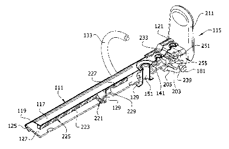
233 relative to the actuator body and closing arm 203. If
the hinge plates 127 have not been pivoted sufficiently
toward the closed position to allow unimpeded movement of
the locking system 221, 225 to the locking position,
continued rotation of the actuator 115 causes the actuator
body 201 and flexible arm to push the cross bar 233 away
from the open end 121 of the housing. The force applied by
the actuator 115 to the cross bar 233 is transferred
through the travel bar to the locking elements 221 so the
angled forward edges 273 thereof push against the tabs 281
to increase the force pivoting the hinge plates toward the
closed position.
[0061] Once the hinge plates 127 pass through the co-
planar position, the housing spring force also urges the
hinge plates to continue pivoting movement toward the close
position. The actuator body 201 and flexible arm 251 push
the locking system 221, 225 to the locking position after
the hinge plates 127 have pivoted sufficiently toward the
closed position to permit this movement. Once the rings 113
are back in the closed position (Fig. 6A), the flexible arm
251 holds the locking system 221, 225 in the Locking
position. Thus, the ring binder mechanism 101 effectively
CA 02727358 2011-01-10
retains loose-leaf pages when ring members 133 are closed,
and limits the risk of the closed ring members 133
unintentionally opening.
[0062] During the closing sequence, the recess 255 is
oriented so the bottom of the recess inclines downward as
the recess extends toward the open end 121 of the housing,
as illustrated in Fig 6D. The downward force exerted on the
cross bar 233 by the flexible arm during closing holds the
cross bar against the bottom of the recess. Consequently,
as the cross bar 233 at the end of the travel bar 225 moves
farther away from the concave surface 265 on the back of
the closing arm 203 during closing, the cross bar moves
closer to the pivot pin 181 and the pivot axis of the
actuator 115 coincident therewith. This reduces the amount
of pivoting needed at the hinge 229 to convert movement of
the cross bar 233 to linear movement of the locking portion
223 of the travel bar 225. Also, the length of the travel
bar 225 remains substantially constant during movement of
the actuator to close the rings. For instance, the overall
length of the travel bar is suitably shortened by no more
than about 1 percent during use of the actuator to close
the rings.
[0063] Figures 8 and 9 illustrate a second embodiment
of a ring mechanism, generally designated 301. Except as
noted, the ring mechanism 301 is substantially the same as
the ring mechanism 101 described above and illustrated in
Figs. 1-7C. The travel bar 325 in this ring mechanism 301
does not include a connector portion formed integrally with
the locking portion 323. Instead, the locking portion 323
of the travel bar 325 is connected to the actuator 115 by a
separate connector 327. As illustrated, in Figs. 8 and 9,
the connector 327 is a wire link. Opposing ends 333 of the
wire link 327 are received in the recess 255 in the
actuator 115 and perform in a manner analogous to the cross
26
CA27273582017-04-07
81667826
bar 233 of the ring mechanism 101 described above. Use of a
separate wire link connector to connect the locking portion
of a travel bar to an actuator is disclosed in greater
detail in commonly-owned application No. 11/610,358
(Published as US 200801241664
[0064] A third embodiment of a ring mechanism,
generally designated 401, is illustrated in Figs. 10-14E.
This embodiment is substantially identical to the ring
mechanism 101 described above, except as noted. The closing
arm 403 of the actuator 415 in this embodiment, includes a
rib 420 connecting the closing arm to the actuator handle
411. The rib 420 enhances the stiffness of the closing arm
403. The rib 420 also splits the flexible arm into two
separate flexible arms 451 extending generally from the
actuator body 421. In the illustrated embodiment, the
flexible arms 451 are substantially identical. The arms 451
are spaced from the rib 420 on opposite sides thereof to
facilitate movement of the arms independently of the rib
420.
[0065] As best illustrated in Fig. 14A, each flexible
arm 451 in its undeformed state is attached at one end 460
to the body 421 of the actuator. The arm 451 curves upward
at a first bend 462 relatively close to the attached end
460. The first bend 462 in the arm is a relatively sharp
bend. The flexible arm 451 extends from the first bend 462
to an inflection point 464 between the first bend and a
relatively broad gentle bend in the opposite direction
extending up to an apex 468 of the flexible arm. On the
opposite side of the apex 468, the flexible arm 451 has a
sharp downward bend 461. A lower arm portion 459 extends
from the sharp downward bend 461 to a free end 463 of the
flexible arm. The lower arm portion 459 and sharp downward
27
CA 02727358 2011-01-10
bend 461 are generally analogous to the lower arm portion
259 and end 261 of the upper arm portion 257 of the
flexible arm 251 in the ring mechanism described above.
[0066] The travel bar 425 in this ring mechanism 401
has a pair of opposing ears 430 extending inward toward one
another in place of the cross bar 233 described above.
Fingers 404, which are suitably substantially rigid in
comparison to the flexible arms 451, extend laterally from
opposite sides of the rib 420. In contrast to the lower arm
portion 259 described above, which has a generally flat
inclined surface facing the cross bar 233, the lower arm
portion 469 of each flexible arm 451 in this ring mechanism
401 has a concave surface facing a respective one of the
fingers 404. Together the concave surfaces 470 of the
flexible arms 451 and fingers 404 of the closing arm 403
define spaces 455 in which the arms 430 of the travel bar
425 may be captured by moving the travel bar during
assembly of the ring mechanism in a manner analogous to the
sequence illustrated in Figs. 5A-5C. The closing arm 403 in
this embodiment does not constrain downward movement of the
end of the travel bar 425 relative to the actuator 415
because there is no part of the closing arm positioned to
prevent the end of the travel bar falling out of the spaces
455. Instead, the concave surfaces 470 on the flexible arms
451 extend around the lower portion of the ears 430 at the
end of the travel bar 423 an amount sufficient to prevent
movement of the ears below the free end 463 of the flexible
arms.
[0067] Operation of the ring mechanism 401 is similar
to operation of the ring mechanism 101 described above,
except as noted. During opening movement of the actuator
415, the fingers 404 pull the ears 430 of the travel bar
425 to move the travel bar 425 toward the non-locking
position. During closing movement of the actuator 415 the
28
CA 02727358 2011-01-10
flexible arms 451 push the ears 430 to move the travel bar
425 to the locking position. The flexible arms 451 deform
to delay movement of the travel bar 425 from the pivoting
movement of the hinge plates 127. In particular, the
flexible arm is compressed at the apex 468 so the lower arm
portion 459 moves toward the handle 411 of the actuator.
The lower arm pertion 459 also rotates about an axis
generally coincident with the sharp bend 461. The
rotational movement of the lower arm portion 459 produced
by this deformation is in the same direction (e.g.,
counterclockwise as illustrated) as rotation of the
actuator 415 during closing. The lower arm portions 459 of
the flexible arms 451 also deform so the concave surfaces
470 (as well as the ears 430 at the end of the travel bar
425) move closer to the pivot axis (e.g., pivot pin 181) of
the actuator 415 during closing. Thus, the actuator 415
sequences movement of the travel bar 425 and hinge plates
127 during closing in a manner that is similar to the
actuator 115 described above. However, the closing arm 403
of this actuator 415 can be made stiffer and stronger than
the closing arm 203 of the actuator 115 described above.
[0068] When introducing elements of the ring binder
mechanisms herein, the articles "a", "an", "the" and "said"
are intended to mean that there are one or more of the
elements. The terms "comprising", "including" and "having"
and variations thereof are intended to be inclusive and
mean that there may be additional elements other than the
listed elements. Moreover, the use of "forward" and
"rearward" and variations of these terms, or the use of
other directional and orientation terms, is made for
convenience, but does not require any particular
orientation of the components.
[0069] As various changes could be made in the above
without departing from the scope of the invention, it is
29
CA 02727358 2011-01-10
intended that all matter contained in the above description
and shown in the accompanying drawings shall be interpreted
as illustrative and not in a limiting sense.