Note: Descriptions are shown in the official language in which they were submitted.
CA 02728008 2011-01-17
Attorney Docket: 2759-2/MBE
ENDODONTIC TOOL AND METHOD
FIELD OF THE INVENTION
[oootl This invention relates to endodontic tools.
BACKGROUND OF THE INVENTION
[00021 An important endodontic procedure, known as a "root canal" procedure,
involves
removing organic material from the root canals of an infected tooth and
filling the canal
with an inert obturating material such as gutta percha gum.
[00031 An effective root canal procedure avoids extraction of the infected
tooth. In this
procedure, a dentist or endodontist utilizes a series of endodontic
instruments, for
example files, for the debridement, cleaning and sterilization of the root
canal. These files
are rotated within the canal to clean the canal surfaces, removing debridement
(organic)
material in the process, facilitating improved irrigation, and in some cases
shaping the
canal for easier filling with the obturating material.
[0004] While this procedure used to be done manually, engine-driven (for
example
motor-driven) rotary tools are now available for providing the rotational
motion necessary
for the effective debridement and cleaning of the root canal. One of the
problems with
such tools, however, is that the rotational force is not completely within the
control of the
dentist or endodontist. Files used for debridement and removal of organic
material work
like augers, moving material out of the root canal via a helical groove. This
effectively
makes the file behave like a screw, driving forward when rotated in the
forward direction
(which may for example, depending upon the orientation of the threads, be the
counter-
clockwise direction) and backing off when rotated in the reverse (for example
clockwise)
direction. However, the threads defining the helical groove can lock or catch
on interior
canal surfaces, especially in constricted and/or curved parts of the canal. If
too much
force is applied to the file at such points the file can break, necessitating
removal of the
-1-
CA 02728008 2011-01-17
broken piece of file which can be a difficult procedure which could ultimately
result in
extraction of the tooth, effectively obviating the benefit of the root canal
procedure.
[0005] Accordingly, a motor-driven tool has been developed which rotates
through a
defined arc in a "forward" direction which drives the file into the canal and
a defined
(typically lesser) arc of rotation in the "reverse" direction which backs the
file out of the
canal. This reduces opportunities for the file to lock or catch on the inner
surfaces of the
canal, while effectively debriding, cleaning and shaping the root canal for
filling. An
example of such a tool is described in U.S. Patent No. 6,293,795 issued
September 25,
2001 to Johnson, which is incorporated herein by reference.
[00061 An instrument such as a file used in a canal for debridement will be
subjected to
stress in the form of torsion (torque). This will cause the structure of the
file material, for
example metal or plastic, to undergo changes. These changes can be reversible
or
irreversible, depending on the amount of torque to which the instrument is
subjected
during the canal debridement. In U.S. Patent No. 6,293,795 the torque set on
the motor
may be higher than the elastic limit of the file; also, the arcs of rotation
in the forward and
reverse directions may subject the tool to torque greater than the elastic
limit of the file.
Therefore, any changes in the material will be irreversible.
[0007] Thus, in the tool described in U.S. Patent No. 6,293,795, if the
instrument locks at
a point where a torque higher than the failure point of the particular file is
being applied,
the file can break in the root canal. If the instrument locks at a point where
a torque
higher than the elastic limit of the file is being applied, initially a non-
visible alteration of
the metal structure will occur, and at a higher torque distortion or visible
deformation of
the file will occur, particularly at a point in the procedure where the
debriding file is
bending through a curve in the canal. If a debriding file is reused, material
fatigue through
successive uses can be cumulative, increasing the likelihood of plastic
distortion or
breaking of the file.
-2-
CA 02728008 2011-01-17
BRIEF DESCRIPTION OF THE DRAWINGS
10008] In drawings which illustrate by way of example only a preferred
embodiment of
the invention,
10009] Figure 1 is a diagrammatic view of a reciprocating endodontic tool
according to
the invention.
iooioi Figure 2 is a graph showing the preferred torque cut off point in the
forward
direction according to the invention.
[00111 Figure 3 is a diagrammatic view illustrating preferred forward and
reverse
rotational arcs according to the invention.
DETAILED DESCRIPTION OF THE INVENTION
100121 It has been discovered that the root canal procedure can be as
effectively
accomplished using a reciprocating endodontic hand tool such as that described
in U.S.
Patent No. 6,293,795, but in which the torque applied to the debriding file
does not
exceed the elastic limit of the file. This makes the root canal procedure far
safer,
considerably reducing or potentially eliminating the possibilities of plastic
distortion and
fatigue, or breakage of the file during the canal debriding/cleaning/shaping
process.
[00131 The invention thus provides a hand-held tool for rotating an endodontic
instrument for preparing a root canal for filling, the tool comprising a chuck
for holding
the instrument, a head associated with motor means for rotating the chuck
alternately in
forward and reverse directions, and a torque sensor for measuring a rotational
torque on
the chuck, such that the instrument can cut the canal, remove debridement
material and
advance in the canal, whereby a torque limit on the chuck does not exceed an
elastic
torque of the instrument.
[00141 In further embodiments the tool comprises a control module for setting
a torque
limit not exceeding an elastic torque of the instrument; a forward arc of
rotation of the
instrument is greater than a reverse arc of rotation of the instrument; the
forward
-3-
CA 02728008 2011-01-17
rotational arc of motion of the chuck is set in the range of about 140 degrees
to about 160
degrees; the forward rotational arc of motion of the chuck is set at about 140
degrees; a
reverse rotational arc of motion of the chuck is set in the range of about 20
degrees to
about 90 degrees; the reverse rotational arc of motion of the chuck is set at
about 30
degrees; or the forward are of rotation of the instrument is substantially
equal to a reverse
arc of rotation of the instrument.
100151 The invention further provides a method of rotating an endodontic
instrument in a
hand-held tool for preparing a root canal for filling, the tool comprising a
chuck for
holding the instrument, a head associated with motor means for rotating the
chuck
alternately in forward and reverse directions, a torque sensor for measuring a
rotational
torque on the chuck, and a control module, the method comprising, in any
order, the steps
of. setting a torque limit not exceeding an elastic torque of the instrument
whereby the
instrument can cut the canal, remove debridement material and advance in the
canal, and
activating the motor.
100161 Further embodiments of the method may comprise the steps of setting a
forward
arc of rotation of the instrument at a limit greater than a limit of a reverse
arc of rotation
of the instrument; setting the forward rotational arc of motion of the chuck
in the range of
about 140 degrees to about 160 degrees; setting the forward rotational arc of
motion of
the chuck at about 140 degrees; setting the reverse rotational are of motion
of the chuck
in the range of about 20 degrees to about 90 degrees; setting the reverse
rotational arc of
motion of the chuck at about 30 degrees; or setting a forward arc of rotation
of the
instrument at a limit substantially equal to a limit of a reverse are of
rotation of the
instrument.
[00171 According to the invention, instrument fatigue due to torsion
(rotation) is virtually
eliminated, because below the elastic limit changes in the material (for
example metal or
plastic) of the instrument 2 due to repeated usage are reversible. In the
preferred
embodiment the forward and reverse rotational arcs 4a, 4b of the instrument 2
are also
selected so as to reduce or eliminate the likelihood that the torque on the
file would
-4-
CA 02728008 2011-01-17
exceed the elastic limit of the file if the file locks on the canal surfaces,
as described
below. The lower the torque applied to the instrument 2, the safer the root
canal
procedure, as long as the endodontic instrument 2 is capable of cutting in the
canal,
removing debris in an upward direction out of the tooth and advancing in the
canal in a
downward direction.
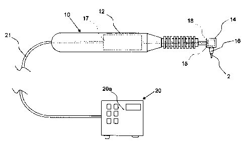
[00181 An endodontic tool 10 according to the invention thus comprises a
handle 12
supporting a rotary head 14 providing a chuck 16 or other attachment means for
inserting
an instrument 2, such as a debriding file or similar endodontic instrument.
The rotary
head 14 may be rotated by any suitable means, including electric, pneumatic or
hydraulic
means, an electric motor 18 being most commonly used as is known to those
skilled in
the art.
[00191 In the table-top version of the tool illustrated in Figure 1, the
handle 12 contains a
motor 17 controlled and powered via a power supply cord 21 attached to a
control module
20. The motor 17 drives the chuck 16 via a gear train 18 disposed within the
rotary head
14. In alternate embodiments (not shown), without limitation, the rotary head
may be
attached to the motor and the motor connected by a cable to a dental chair
system which
rotates the motor by any suitable means, including electric, pneumatic or
hydraulic
means; the control module can be disposed within or on the motor, or within or
on the
rotary head or part of the dental chair system, for example in a battery-
operated hand held
device; or the rotary head may provide means for setting the parameters
electrically or
mechanically. The invention is not limited to any particular configuration or
arrangement
of the tool 10, motor 17 or drive means 18 used to drive the rotary head 14.
100201 The control module 20 provides controls for the user of the tool 10 to
set such
parameters as the speed, arc of rotation, torque and others, for example as
described in
U.S. Patent No. 6,293,795 which is incorporated herein by reference. An
example of a
suitable reciprocating endodontic tool is the Endojolly Tecnika Electrodontic
Micromotor
(Trademark) by ATR, SAS of Pistoia, Italy.
-5-
CA 02728008 2011-01-17
[00211 A microprocessor in the control module 20 receives data from the user
input into
the control module user interface 20a to set the desired parameters for the
forward and
reverse arcs of rotation 4a, 4b of the reciprocating motion, a torque limit at
which the
motor 17 will cease rotating in the current direction, and the rotational
speed of the chuck
(which may differ in the forward and reverse directions). According to the
invention, the
maximum amount of torque to be applied to the debriding file 2 in the forward
and the
reverse directions is set so as not to exceed the elastic limit of the
specific instrument 2
being used, which may vary according to the composition and configuration of
the
instrument 2.
100221 In the preferred embodiment the preset forward and reverse arcs of
rotation 4a, 4b
should not subject the instrument 2 at any particular moment, or in any
situation, to a
torque (torsional stress) higher than the elastic limit of the specific file 2
being used.
[00231 The elastic limit is in part based on the thickness and composition of
the
instrument 2. Materials such as those used for debriding files have a
quantifiable
relationship between applied stress and the resulting strain on the material,
which can be
represented by a stress-strain curve such as that illustrated in Figure 2. The
slope of the
stress-strain curve is constant over the region of elastic strain. The point
where applied
stress causes the onset of permanent deformation is defined as the "elastic
limit," as
reflected by the change in the slope of the stress-strain curve.
[00241 The elastic limit of the instrument 2 can be determined by stress-
strain tests, and
may optionally be provided by the manufacturer of the instrument 2 on the
packaging or
literature accompanying the instrument 2. Ideally the elastic limit is
determined by
measurements taken at about 1 mm from the tip of the instrument, however tests
at this
point can be very difficult to realize because the tip of a file is very fine
and tends to slip
out of the vice connected to the torque sensor. Accordingly, measurements on
endodontic
instruments are usually taken at 2 to 3 mm from the tip, to determine for
example torque
at fracture, angle at fracture and other parameters. These measurements may
also (or
alternatively) be taken at different points along the instrument.
-6-
CA 02728008 2011-01-17
100251 In use, the user (typically an endodontist or dentist) uses the user
interface 20a of
the control module 20 to set the limits of the forward and reverse rotational
arcs 4a, 4b of
the reciprocating motion (as shown by way of example in Figure 3), the speed
(or speeds)
in the forward and reverse directions, and the torque limit in the forward and
reverse
directions to be applied before the motor 18 stops rotating in one direction
and starts
rotating in the opposite direction. The motor 18 will stop rotating in the
current direction
(for example the forward direction) and start rotating in the opposite
direction (for
example the reverse direction) when either the preset limit of the arc of
rotation is reached
or when the preset torque limit is reached in the current direction. The
torque sensor 15 in
the head 14 delivers torque readings via the cable 21 to the control centre
20, which is
programmed to arrest rotation (in the first direction, for example) of the
chuck 16 and to
reverse its direction of rotation when the programmed torque limit set for the
first
direction is reached. As noted herein, according to the present invention the
preferred
torque limit is set at a value not exceeding the elastic limit of the
instrument 2, and
preferably the lowest torque value which allows the endodontic instrument 2 to
cut in the
canal, remove debris in an outward direction (i.e. out of the tooth) and
advance in the
canal.
[00261 As noted, the smaller the torque limit, the safer the canal debridement
procedure
as long as the endodontic file can still cut in the canal, remove debris in an
outward
direction (out of the tooth) and advance in the canal in an inward direction
(deeper into
the canal). Thus, according to the present invention the preferred torque
limit in the
forward and reverse directions set via the control centre 20 should not exceed
the elastic
limit of the debriding file 2. It has been discovered that this provides a
safety advantage
without reducing the efficacy of the root canal procedure. The arcs of
rotation in the
forward and reverse directions 4a, 4b set on the control centre 20 should
similarly be set
so as not to subject the file 2 to a torque exceeding the elastic limit of the
particular
endodontic instrument 2 being used.
-7-
CA 02728008 2011-01-17
100271 The rotational arcs 4a, 4b in the forward and reverse directions may be
the same,
or the rotational are limit in the forward direction 4a (referred to herein as
the direction in
which, due to the orientation of the helical thread, the thread of the file 2
will drive the
file 2 deeper into the canal) may be less than the rotational are limit in the
reverse
direction 4b; however, preferably the rotational arc limit in the forward
direction 4a is
greater than the rotational arc limit in the reverse direction 4b, as shown in
Figure 3. In
the preferred embodiment the forward arc of rotation 4a is set at about 140 to
160
degrees, most preferably about 150 degrees, and the normal reverse arc of
rotation 4b (i.e.
the rotational arc limit during normal operation of the tool 10 in the absence
of excessive
torque) is set at about 20 to 90 degrees, most preferably around 30 degrees.
Optionally a
setting may be provided for a secondary reverse are of rotation (not shown),
engaged
when the forward rotational torque limit is exceeded, which may be a different
value than
the normal reverse arc of rotation 4b.
[00281 Any endodontic instrument, rotary or reciprocating, can fracture during
the
debridement of a root canal. There are three different types of instrument
fracture:
flexural (bending) fatigue fracture, torsional fatigue fracture and torsional
fracture.
[00291 Fracture can be caused by flexural fatigue when the instrument is used
in a curved
canal. Tension/compression cycles are generated on the instrument at the point
of
maximum flexure. This repeated tension-compression cycle, caused by rotation
within
curved canals, increases cyclic fatigue of the instrument over time and may be
an
important factor in instrument fracture. This type of fracture happens mainly
in severely
curved canals. The best way to reduce the incidence of this type of fracture
is by
discarding and replacing the instrument frequently.
[00301 Torsional fracture occurs when the endodontic instrument 2 used for
debridement
binds or locks in the canal. It will then be subjected to a stress/torque
mainly at its tip. As
the motor 18 continues rotating the instrument 2, the force or torque at the
tip of the
instrument 2 increases and the instrument 2 will eventually fracture at a
specific angle of
rotation. Each instrument will fracture when subjected to a specific torque,
and it will
-8-
CA 02728008 2011-01-17
fracture at a specific angle. Every time an instrument is used in a canal it
is also subjected
to torsional fatigue resulting from the repeated engagement of the canal
walls. Like
bending or flexular fatigue, torsional fatigue can lead to fracture.
100311 One way to avoid torsional fracture is by setting a maximum amount of
torque to
be applied to a file that will avoid exceeding breaking stresses (the failure
point of the
material), as in U.S. Patent No. 6,293,795. However, in such prior art devices
and
procedures the torque and the arcs of rotation set on the tool (motor 18) may
be within the
plastic phase of the instrument, leading to irreversible changes in the
instrument material
(whether visible or invisible), which could lead to instrument deformation
(distortion)
and potentially fracture due to fatigue associated with repeated usage of the
instrument 2
in the canal.
[00321 According to the present invention, the torque limits for the forward
and reverse
directions are set so as not to exceed the elastic limit of the file.
Responsive to the torque
sensor 15, the control module 20 switches the motor 18 to the other direction
of rotation
if the sensed torque reaches the preset limit, which is within the elastic
deformation
phase. Also, the forward and reverse arcs of rotation 4a, 4b are set to avoid
rotation of the
instrument 2 to a point where torque to which the instrument 2 is subjected,
if it is locked
in the canal, would exceed the elastic limit of the instrument 2. The control
module 20
will cause the motor 18 to reverse the rotation of the instrument 2 when the
preset are of
rotation is completed even if the torque to which the chuck 16 is subjected
does not reach
the preset torque limit.
100331 In operation, an instrument 2 such as a debridement file is secured to
the chuck
16. The operator (typically a dentist or endodontist) uses the user interface
20a to program
the control module 20 with at least the torque limit (as determined for the
particular
instrument 2 being used), and the forward and reverse arcs of rotation 4a, 4b.
The user,
holding the handle 12 of the tool 10, performs the root canal procedure using
the tool 10
to rotate the instrument 2 in reciprocating fashion. The torque sensor 15
sends a constant
(or frequent intermittent) signal to the control module 20 while the
instrument 2 is
-9-
CA 02728008 2011-01-17
rotating. If the instrument 2 bites into the canal to the point that the
torque against the
instrument 2 exceeds the preset torque limit, the control module 20 reverses
the rotational
direction for a preset torque-relief rotational arc (which may be the same as
the normal
reverse rotational arc 4b, or may be set at a different value).
[00341 Various embodiments of the present invention having been thus described
in
detail by way of example, it will be apparent to those skilled in the art that
variations and
modifications may be made without departing from the invention. The invention
includes
all such variations and modifications as fall within the scope of the appended
claims.
-10-