Note: Descriptions are shown in the official language in which they were submitted.
CA 02728108 2013-07-16
MAGNETIC ASSEMBIN AND METHOD FOR DEFINING A MAGNETIC
FIELD FOR, AN IMAGING VOLUME
Cross-Reference To Related Application
190011 This nt'plication claims priority from United StaieN provisionai
pat"'
Application Serial No. 611129,412 tiled June 24,'2008.
Field of the invention
100921 The present invention relates generally to magnetic fields with
predetermined
specially desired charaeterislics, zmd more particularly to ma,unetie assembly
and method for
delming a magnetic field for an imaging' volume.
Background of the Invention
100031 Magnetic Resonance Imaging_ or MRI, is a well-known imaging
technique
during which an object, such as a lannan patient. is placed into an MR1
machine and subjected
to a unitilrin magnetic field produced by a polarizing magnet housed within
the MR I machine.
Radio frequency (RF) pulses, generated by ui RI coil housed within the MR I
machine, are
used to scan target tissue 4,1 the patient, MRI signals are radiated by
excited nuclei in the
target tissue iii Ike intervals between consecutive RI; pulses and are sensed
by the RP' coil.
During MR! signal sensing, finely controlled magnetic field gradients are
switched rapidly to
alter the uniThrm magnetic held at localized areas thereby to allow spatial
Ioeal izal ion of MRI
signals radiated by selected slices of the target tissue. The, sensed MRE
signals are in turn.
digitind and processed to reconstruct images of the target tissue slices using
one of many
known techniques.
100941 In a system capable of perRIrming NI R I, a sirong uniform static
magnetic
field is required in order to align the nuclear spins of the obieci within a
particular imaging
V( lume. This unirorm static magnetic field is normally produced by a
permanent or coil
magnet assembly with a magnetic field strength on the order 0(0,1 to 4.7 Testa
within the
imaging volume. During sensing. the finely controlled magnetic field gradients
imposed in
the imaging volume allow for discrimination amongst nuclear spins at different
locations.
However, inhornoge.neilies in the static mattnetieõ acid within the imaging
volume are
inseparable from the magnetic rield gradictus during image aequisii ion and
directly lead to
geometric distortions in the resulting images. Tlu.%;e distortions are
especially detrimental
when the MR1 system is to be used in conjunction with another procedure that
relies on the =
geometric accuracy of the acquired images, such as. but not limited to.
radiation therapy.
Consequently. significantly reducing static magnetic field inhomogencitics is
extremely
CA 02728108 2010-12-15
WO 2009/155691
PCT/CA2009/000860
- 2 -
important in order to achieve images that are of a high quality and that have
a high degree of
geometric accuracy. For example, acceptable image quality can be achieved
where the level
of inhomogeneity is on the order of 10 ppm within the imaging volume.
[0005] It is known to reduce axisymmetric and non-axisymmetric static
magnetic
field inhomogeneities using techniques such as passive shimming. Passive
shimming is
performed after the magnetic assembly has been manufactured, and involves
strategically
placing additional pieces of magnetic material in and around the imaging
volume. The
additional pieces of magnetic material are typically of various shapes
including rings, ring
segments, cylinders, and prisms. While shimming has in some applications been
effective in
limiting inhomogeneity in the imaging volume, its effectiveness is limited by
the extent to
which the initial field inhomogeneities are present after manufacturing. As
such, significant
constraints are placed on the design of magnet assemblies, and by the
requirement of
maintaining a suitably large and accessible space within the magnet assembly
for the object
being examined.
[0006] Attempts to circumvent the limitations of passive shimming
techniques have
been made by improving the design of the manufactured magnet assemblies in
order to reduce
inherent axisymmetric field inhomogeneities. In the present state of the art
for hi-planar
magnets, the opposing surfaces of the magnet pole pieces are contoured in such
a way that the
pole pieces are shaped axisymmetrically about an axis generally extending
towards the
opposing pole piece surface. For example, the most common such pole piece
design is known
as a rose-ring design, in which the surface of the pole piece which is closest
to the imaging
volume is entirely flat with the exception of a ring of magnetic material
placed along the
periphery of the said pole piece surface. More particularly, a graph of axial
distance of the
pole piece surface along the axis, versus radial distance from the axis is a
line of zero slope
with a single vertical step at the radial position of the rose-ring.
[0007] One magnet assembly design disclosed in U.S. Pat. No. 5,539,366
consists of
axisymmetrically shaped pole pieces for which a graph of axial distance, of
the pole piece
surface along the axis, versus radial distance from the axis is a piece-wise
linear curve, or is a
non-linear curve having a continuous slope with at least two sign reversals.
Both such
designs are limited in that points on the surface regions of the pole pieces
located an identical
radial distance from the axis are also located a common axial distance along
the axis, and thus
only axisymmetric magnetic field inhomogeneities can be reduced prior to
shimming.
Furthermore, these systems are massive and immobile as the pole piece sizes
are necessarily
very large, and therefore are not suitable for movement relative to the
subject being examined.
CA 02728108 2010-12-15
WO 2009/155691
PCT/CA2009/000860
-3-
100081 Often other objects and/or devices are placed in the vicinity of an
MRI
device. For example, described in PCT Patent Application Publication Number WO
2007/045076 Al to Fallone et al., the contents of which are incorporated
entirely herein by
reference, is an integrated external beam radiotherapy and MRI system, wherein
a linear
accelerator (linac) is coupled to an MRI apparatus for providing simultaneous
imaging and
treatment. Unfortunely, current state of the art magnet assembly design does
not address the
effects of including objects or additional therapeutic or diagnostic devices
within or proximate
to the magnet assemblies, while providing acceptably homogeneous imaging
volumes and/or
other volumes with specific magnetic field properties, and ensuring that the
size of the magnet
assembly is manageable. The operation of such additional devices may be
affected by the
presence and/or characteristics of the magnetic field at their location and
may themselves alter
the characteristics of the magnetic field in the imaging volume. Furthermore,
the
incorporation of such objects or devices within or proximate the magnet
assembly may
require a particular volume of free space to be vacated from the magnet
assembly, such as a
large hole through the magnet structure, either for placement of the object or
device, or for
providing a benefit in performance of the object or device itself. For
example, it may be
advantageous to align the magnetic fields produced by a magnet assembly with
the direction
of electrons in a linac waveguide (or the protons produced by the linac for
proton therapy) for
image guided radiotherapy, particularly to reduce subsequent perturbations in
patient
radiation dosimetry. In general, such vacated volumes significantly affect the
magnetic field
produced by the magnet assembly and contribute to a highly inhomogeneous field
in the
imaging volume.
[0009] It is therefore an object of the invention to provide a magnet
assembly and a
method for defining a magnetic field for an imaging volume for that mitigates
or obviates at
least one of the above-described disadvantages of the prior art.
Summary of the Invention
1000101 In accordance with an aspect, there is provided a magnet assembly
comprising:
at least two magnets arranged in a fixed spaced relationship with one another
thereby to define a space between the magnets that encompasses an imaging
volume, each of
the magnets producing a variety of magnetic field strengths across inward-
facing surfaces
thereof that, in combination, produce a substantially homogeneous magnetic
field in the
imaging volume.
CA 02728108 2010-12-15
WO 2009/155691
PCT/CA2009/000860
-4-
1000111 The variety of magnetic fields across the inward-facing surfaces of
the
magnets enables production of a substantially homogenous magnetic field that
is acceptable
for imaging in an imaging volume, and that is of a sufficient size without
necessarily resorting
to use of very large magnets. As such, the production of a variety of magnetic
fields across
the inward-facing surfaces of the magnets provide a configuration that enables
a more
compact magnet assembly for a given imaging volume.
[00012] In accordance with another aspect, there is provided a Magnetic
Resonance
Imaging (MRI) device comprising:
the magnet assembly described above; and
a detector detecting radiofrequency signals emitted by protons within the
imaging volume when re-aligning with the substantially homogeneous magnetic
field after
perturbation, wherein imaging is based on the detected radiofrequency signals.
[00013] In accordance with another aspect, there is provided a method of
defining a
magnetic field for an imaging volume, the method comprising:
generating an initial model of a magnet assembly;
estimating a magnetic field for the imaging volume based on the model;
calculating deviation between the estimated magnetic field and a target
magnetic field for the imaging volume; and
updating the model to reduce the deviation by modifying the magnet
assembly to produce a variety of magnetic field strengths that, in
combination, produce
substantially the target magnetic field.
[00014] In an embodiment, the target magnetic field is a magnetic field
that is
acceptably homogeneous, the initial model is based on parameters specifying
the magnet
assembly, and the modifying comprises modifying one or more parameters
representing the
surface geometry of one or both inward-facing surfaces of two magnets of the
magnet
assembly.
[00015] According to another aspect, there is provided a computer readable
medium
having a computer readable program thereon for defining a magnetic field for
an imaging
volume, the computer program comprising:
computer program code generating an initial model of a magnet assembly;
computer program code estimating a magnetic field for the imaging volume
based on the model;
computer program code calculating deviation between the estimated magnetic
field and a target magnetic field for the imaging volume; and
CA 02728108 2015-08-12
- 5 -
computer program code updating the model to reduce the deviation by modifying
the magnet
assembly to produce a variety of magnetic field strengths that, in
combination, produce
substantially the target magnetic field in the imaging volume.
[00016] In accordance with another aspect, there is provided a magnet
assembly
comprising:
at least two magnets arranged in a fixed spaced relationship with one another
thereby to define a space therebetween, each of the magnets producing a
variety of magnetic
field strengths across inward-facing surfaces thereof that, in combination,
produce a target
magnetic field in a target volume.
[00017] In accordance with still another aspect, there is provided a
method of defining
a magnetic field for a target volume, the method comprising:
-
generating an initial model of a magnet assembly;
estimating a magnetic field for the target volume based on the model;
calculating deviation between the estimated magnetic field and a target
magnetic field for the target volume; and
updating the model to reduce the deviation by modifying the magnet
assembly to produce a variety of magnetic field strengths that, in
combination, produce
substantially the target magnetic field in the target volume.
[00018] In accordance with still another aspect, there is provided a
computer readable
medium embodying a computer program for defining a magnetic field for a target
volume, the
computer program comprising:
computer program code generating an initial model of a magnet assembly;
computer program code estimating a magnetic field for the target volume
based on the model;
computer program code calculating deviation between the estimated magnetic
field and a target magnetic field for the target volume; and
computer program code updating the model to reduce the deviation by
modifying the magnet assembly to produce a variety of magnetic field strengths
that, in
combination, produce substantially the target magnetic field in the target
volume.
100018a] In accordance with still another aspect, there is provided a
magnet assembly
comprising:
at least two magnets arranged in a fixed spaced relationship with one another
thereby to define a space between the magnets that encompasses an imaging
volume, each of
the magnets producing a variety of magnetic field strengths across inward-
facing surfaces
CA 02728108 2015-08-12
- 5a -
thereof that, in combination, produce an acceptably homogeneous magnetic field
in the
imaging volume;
wherein the inward-facing surface of at least one of the magnets has a non-
axisymmetrical geometry.
[00018b] In accordance with still another aspect, there is provided a
magnet assembly
comprising:
at least two magnets arranged in a fixed spaced relationship with one another
thereby to define a space therebetween, each of the magnets producing a
variety of magnetic
field strengths across inward-facing surfaces thereof that, in combination,
produce a target
magnetic field in a target volume;
wherein the inward-facing surface of at least one of the magnets has a non-
axisymmetrical geometry.
[00018c] In accordance with still another aspect, there is provided a
method of defining
a magnetic field for a target volume, the method comprising:
generating a model of:
a magnet assembly comprising at least two magnets arranged in a fixed
spaced relationship having an axis extending generally from a center the first
magnet
to a center of the second magnet; and
one or more objects capable of disturbing the magnetic field in the target
volume in a manner that would cause the magnetic field in the target volume to
be
unacceptably inhomogeneous;
estimating the magnetic field for the target volume based on the model;
calculating deviation between the estimated magnetic field and a target
magnetic field
for the target volume; and
updating the model to reduce the deviation by non-axisymmetrically modifying
one
or more parameters representing the magnet assembly to produce a variety of
magnetic field
strengths that, in combination, produce substantially the target magnetic
field in the target
volume.
100018d1 In accordance with still another aspect, there is provided a
computer readable
medium having stored thereon instructions, which when executed by a processor
cause the
processor to implement the method of
generating a model of:
a magnet assembly comprising at least two magnets arranged in a fixed
spaced relationship having an axis extending generally from a center the first
magnet
to a center of the second magnet; and
CA 02728108 2015-08-12
- 5b -
one or more objects capable of disturbing the magnetic field in the target
volume in a manner that would cause the magnetic field in the target volume to
be
unacceptably inhomogeneous;
estimating the magnetic field for the target volume based on the model;
calculating deviation between the estimated magnetic field and a target
magnetic field
for the target volume; and
updating the model to reduce the deviation by non-axisymmetrically modifying
one
or more parameters representing the magnet assembly to produce a variety of
magnetic field
strengths that, in combination, produce substantially the target magnetic
field in the target
volume.
[00018e] In accordance with still a further aspect, there is provided a
method of
defining a target magnetic field for a target volume in a Magnetic Resonance
Imaging (MRI)
machine, the method comprising:
generating an initial model comprising:
a magnet assembly comprising a first magnet and a second magnet
maintained in a fixed spaced relationship by a yoke assembly, the magnet
assembly
having an axis extending generally from a center of the first magnet to a
center of the
second magnet, the first and second magnets being axisymmetrically shaped; and
one or more fixed objects capable of disturbing the magnetic field in the
target volume in a non-axisymmetric manner that would cause the magnetic field
in
the target volume to be unacceptably inhomogeneous for imaging;
estimating a magnetic field for the target volume based on the model;
calculating deviation between the estimated magnetic field and the target
magnetic
field for the target volume; and
updating the model to reduce the deviation by non-axisymmetrically modifying
one
or more parameters representing one or both of the first and second magnets to
produce a
variety of magnetic field strengths that, in combination, produce
substantially the target
magnetic field in the imaging volume.
[00019] The method described herein can be applied to the computer-based
design of
magnetic assemblies for use in medical applications, particularly those
involving Magnetic
Resonance Imaging (MRI) where a bi-planar magnet configuration (eg. Helmholtz
type) is to
be employed. Such bi-planar magnet assemblies include those with spaced-apart
first and
second pole pieces with generally opposing first and second pole faces, such
as, but not
limited to, C-shaped magnets, two column magnets, or four column magnets. In
such
=
CA 02728108 2010-12-15
WO 2009/155691
PCT/CA2009/000860
- 6 -
applications, the method can be utilized to produce magnet assemblies which
produce a
substantially uniform magnetic field in a particular imaging volume by way of
reduction of
axisymmetric and/or non-axisymmetric field inhomogeneities. More generally,
the method
described herein may be employed to produce a magnetic field with specially
desired
characteristics in a particular region within or proximate the magnetic
assembly where
additional objects or devices may be located whose operation may be affected
by the presence
and/or characteristics of the magnetic field. Such objects or devices may be x-
ray tubes,
medical linear accelerator waveguides (linac), flat-panel imagers, nuclear
medicine or
ultrasound imagers, or other devices. Such devices may be placed at the ends
of the open
space between the two poles. The method described herein is also applicable to
the definition
of a magnetic field in an imaging volume for magnet assemblies that include an
opening in
one or both of the magnet poles either in the centre or at any location, for
positioning of any
device at that location. Such placement may be provided for design or
operational advantage,
such as reduction in size and/or reducing perturbations in patient dosimetry
in a treatment
system that is integrated with imaging system and/or producing a particular
magnetic field.
For example, one particular configuration would be the positioning of a linear
accelerator
(linac) at a location within the magnet structure where the direction of
electrons in the
waveguide or photons produced by them is parallel to the magnetic field
produced by the
magnet thus decreasing the subsequent perturbations in patient radiation
dosimetry.
[00020] Another benefit of the method disclosed herein is that it is
applicable to
numerous uses. For example, while in many applications it is desirable that
there be a
substantially homogeneous magnetic field in an imaging volume, the magnetic
field in the
imaging volume may, in certain applications, be a desired though substantially
non-
homogeneous magnetic field having a particularly desired gradient, for
example. More
generally, the invention may be employed for the defining of magnetic fields
in volumes not
intended for imaging. For example, it may be desired to define a magnetic
field for a volume
for directing/guiding/changing the path of an electron or proton beam such as
is done
currently with the use of bending magnets.
[00021] The magnet assembly and method described herein may be applied in
systems that integrate external beam radiotherapy and MRI systems and even
such systems
configured for use in rotation mode, such as those described in PCT Patent
Applications
Publication Nos. WO 2007/045076 Al and WO 2007/045075 Al both to Fallone et
al., the
contents of each of which are incorporated herein by reference in their
entirety.
Brief Description of the Drawings
CA 02728108 2010-12-15
WO 2009/155691
PCT/CA2009/000860
-7-
1000221 Embodiments will now be described more fully with reference to the
accompanying drawings in which:
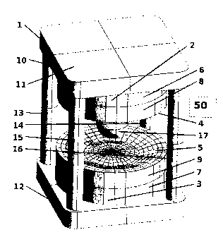
[00023] Figure 1 is a perspective view of an open compact magnet assembly
according to an embodiment;
[00024] Figure 2 is a cross-sectional view of an open compact magnet
assembly of the
present invention, including a direct view of the pole assembly surface and
the distribution of
variable design parameters representing locations on the pole assembly
surface;
[00025] Figure 3 is a graph plotting the radial position versus the angular
position of
the variable design parameter distribution of locations on the pole assembly
surface;
[00026] Figure 4 is a perspective view of a contoured non-axisymmetric pole
assembly in isolation according to an embodiment;
[00027] Figure 5 is a perspective view of an alternative open compact
magnet
assembly, having in particular two large holes vacated through the entire
magnet assembly;
[00028] Figure 6 is a perspective view of a planar-faced ferromagnetic pole
piece in
an initial model of a magnet assembly, having a large hole vacated
therethrough, along with
the distribution of surface locations represented by variable design
parameters;
[00029] Figure 7 is a perspective view of an axisynunetrically contoured
ferromagnetic pole piece resulting from application of the method to the
magnet assembly
incorporating the pole piece of Figure 6;
1000301 Figure 8 is a flowchart showing steps for defining a magnetic field
for an
imaging volume according to an embodiment;
[00031] Figure 9 is a flowchart better illustrating the steps for
generating an initial
model of a magnet assembly as shown in Figure 8; and
[00032] Figure 10 is a flowchart better illustrating the steps for
calculating deviation
from a target magnetic field in the form of an objective function as shown in
Figure 8.
Detailed Description of the Embodiments
1000331 Referring now to the drawings wherein like numerals indicate like
elements
throughout, Figures 1-4 show a magnet assembly 1 according to an embodiment.
In this
embodiment, magnet assembly 1 includes a first ferromagnetic pole assembly 2
and a second
ferromagnetic pole assembly 3. The first and second ferromagnetic pole
assemblies 2, 3 are
arranged in a fixed, spaced relationship with one another as "biplanar"
magnets thereby to
define a space therebetween that encompasses an imaging volume 17 and is large
enough to
receive an object (not shown) to be imaged at the imaging volume 17. The
magnet assembly
CA 02728108 2010-12-15
WO 2009/155691
PCT/CA2009/000860
- 8 -
1 is "open" as the object to be imaged can be moved between the pole
assemblies 2, 3 to be
positioned at the imaging volume 17.
[00034] In this embodiment, each of the first and second pole assemblies 2,
3
comprises both a cylindrical permanent magnet piece 6 (7) and a substantially
cylindrical
ferromagnetic piece 8 (9). The permanent magnet piece 6 (7) and substantially
cylindrical
ferromagnetic piece 8 (9) are arranged such that the ferromagnetic piece 8 (9)
is positioned
between the imaging volume 17 and the permanent magnet piece 6 (7). Inward-
facing
surfaces, or "pole faces" 4, 5 are adjacent to the space between the first and
second pole
assemblies 2 and 3. As will be described in further detail herein, each of the
first and second
ferromagnetic pole assemblies 2, 3 produce a variety of magnetic field
strengths across their
inward-facing surfaces 4, 5 to produce an acceptably homogeneous magnetic
field in the
imaging volume. In this embodiment, an acceptably homogeneous magnetic field
is one that
comprises about 10 ppm, or less, of magnetic field inhomogeneity. This level
of
inhomogeneity is considered acceptable for use in Magnetic Resonance Imaging
(MRI)
devices such as those that base imaging on radio frequency signals emitted by
protons and
detected by a detector 50 within the imaging volume 17 when re-aligning with
the
substantially homogeneous magnetic field after perturbation.
[00035] The ferromagnetic pieces 8, 9 are referred to as "substantially"
cylindrical as
opposed to strictly cylindrical because while the ferromagnetic pieces 8,9 are
circular when
viewed from above (or below) in Figure 1, respective inward-facing, or
"opposing" surfaces
or pole faces 4, 5 are not strictly planar in this embodiment. Rather, each
ferromagnetic piece
8, 9 is shaped to have a variety of thicknesses of magnetic material (when
viewed cross-
sectionally) thereby to produce the variety of magnetic field strengths across
inward-facing
surfaces 4 and 5.
[00036] In this embodiment, the magnet assembly 1 also includes a yoke
structure 10
with first and second yoke plates 11 and 12 connected with four columns 13-16.
The first
pole assembly 2 is connected to the inward-facing surface of the first yoke
plate 11 which is
closest to the second yoke plate 12. Similarly, the second pole assembly 3 is
connected to the
inward-facing surface of the second yoke plate 12.
[00037] As will be understood, in certain magnet applications, such as MRI,
a high
overall magnetic field strength is required in the imaging volume 17. In this
embodiment, to
achieve this high magnetic field strength permanent magnet pieces 6 and 7 are
formed of a
Neodymium-Iron-Boron compound. In an alternative embodiment, another material
or
materials that are permanently magnetized and have a high maximum energy
product may be
employed. Furthermore, ferromagnetic pieces 8, 9 and the yoke structure 10 are
each formed
CA 02728108 2010-12-15
WO 2009/155691
PCT/CA2009/000860
- 9 -
of iron-bearing material such as steel. As has been described above, it is
advantageous
particularly for MRI applications to have excellent magnetic field homogeneity
in the imaging
volume. However, in prior known magnet assemblies, particularly those having
planar pole
faces, the magnetic field produced by the magnet assembly has generally a poor
level of
homogeneity. Furthermore, in prior known magnet assemblies, due to the non-
axisymmetric
shape of the entire magnet assembly and in particular due to the non-
axisymmetric shape of
the yoke structure, magnetic field inhomogeneities in the imaging volume are
accordingly
both axisymmetric and non-axisymmetric. As a result, any volume of space that
contains an
acceptably homogenous magnetic field (i.e. suitable for imaging) in such prior
known magnet
assemblies is very small compared to the overall size of the magnet assembly,
requiring very
large magnets to achieve a sufficiently-sized imaging volume.
[00038] Described herein with reference to Figure 8 is a method for
defining a
magnetic field for an imaging volume. During the method, an initial model of a
magnet
assembly 1 is generated (step 100), and a magnetic field for the imaging
volume is determined
based on the model (step 200). A deviation between the magnetic field and a
target magnetic
field for the imaging volume is calculated (step 300), and the model is
updated to reduce the
deviation by modifying the magnet assembly 1 to produce a variety of magnetic
field
strengths that, in combination, produce substantially the target magnetic
field in the imaging
volume (step 400).
[00039] If after the updating at step 400 it is determined at that re-
iteration is required
(step 500), the estimating, calculating and updating steps are performed
again.
[00040] In this embodiment, the target magnetic field is a homogeneous
magnetic
field, such that producing substantially the target magnetic field in the
imaging volume
produces a substantially homogeneous magnetic field in the imaging volume.
[00041] Figure 9 shows in further detail the steps for generating an
initial model of
the magnet assembly 1, as shown in step 100, above. First, a design
parameterization for the
magnet assembly 1 that defines parameters representing the shape, dimensions
and materials
of the magnets and of the magnet assembly 1 is selected (step 110).
1000421 Constraints are then defined (step 112) such that the parameters
are given
initial values and designated as either variable or invariable. The initial
values of the design
parameters may be selected or predefined in any fashion, including
empirically, arbitrarily, or
randomly, provided they satisfy the specified constraints. For example, in
this embodiment,
the materials of the magnet assembly 1 are defined initially as representing
the magnetic
properties of steel and Neodymium-lion-Boron compound as described above but
designated
as invariable such that during the updating of the model the materials may not
be varied. On
CA 02728108 2010-12-15
WO 2009/155691
PCT/CA2009/000860
- 10 -
the other hand, in this embodiment the parameters representing the surface
geometry of the
inward-facing surfaces of the magnets are defined initially as representing
planar or "flat"
inward-facing surfaces but are designated as variable such that they may be
modified to
optimize their shape during the updating to produce non-planar inward-facing
surfaces as
shown in Figure 1.
[00043] With the parameterization, parameter initial values and constraints
having
been defined thereby to generate the initial model of the magnet assembly
(step 114), the
magnetic field produced by the initial magnet assembly, and particularly for
the imaging
volume of interest, is then estimated using a simulation technique employing
the finite
element method (FEM) or a boundary element method (BEM) (step 300)
[00044] With the magnetic field having been estimated, the deviation
between the
target magnetic field and the magnetic field produced by the magnet assembly
as represented
by the initial model is then calculated. The deviation to be reduced and
preferably minimized
is defined as an objective function NY (step 310), which can be explicitly or
implicitly
determined by the set of design parameters. In this embodiment, the objective
function 111
contains at least one term if i (labelled with the index i = 1, 2, ...) for
each of the regions in
which the magnetic field is to be optimized. Thus, at least one term is
present, if j, which in
this embodiment is a calculation of the deviation of the actual magnetic field
from that of a
perfectly homogenous magnetic field over the imaging volume 17, as shown in
Equation (1)
below:
= (B(r)¨ B0)2 clf1 (1)
where:
B(r) is the magnetic field strength at the location r; and
Bo is the desired magnetic field strength.
[00045] In this embodiment, the location of the desired magnetic field
strength Bo is
the point of isocenter of the magnet assembly, or at the center point of the
imaging volume
17. In this embodiment, both of these points coincide. The integral in
Equation (1) is
evaluated over the imaging volume 17, denoted mathematically as SI J. The
objective function
if contains at least one term for each of the regions in which the magnetic
field is to be
defined. In this embodiment, at least one term of the objective function NI,
is a measure of the
deviation of the actual magnetic field from that of a perfectly homogenous
magnetic field,
calculated over the imaging volume. However, if it is desired that other
regions are also to be
optimized, each region has an associated term that is similarly a measure of
the deviation of
the actual magnetic field from that which is desired in that region,
calculated over the region's
CA 02728108 2010-12-15
WO 2009/155691
PCT/CA2009/000860
¨ 11 -
associated volume. In such a case, the other regions, denoted as [2 1, require
deviation
reduction and the ith term of the objective
function NI/ is calculated as shown in Equation
(2), below:
= j (BO ¨ B;(r))2 dfli (2)
Q,
where:
B(r) is the magnetic field at the location r; and
09 is the desired magnetic field at the location r.
[00046] In this case, the preferred total objective function if
representing the
deviation of the magnetic field estimated to be produced by the magnet
assembly 1 from the
target magnetic field is calculated simply as a weighted sum of the individual
terms (step
312), as shown in Equation (3) below:
= EwiTi (3)
where:
wi is the user-defined weight for the ith term '1's.
[00047] The weights wi serve to scale the individual terms AV; in the sum
according to
their importance as determined by the user. For example, the imaging volume 17
center point
may be accorded a higher weight than a point coinciding with another object or
device (such
as a detector 50 or a linear accelerator at some position proximate the magnet
assembly 1) in
order to favour imaging volume homogeneity over interference mitigation.
[00048] It will be understood that alternative definitions of the objective
function and
its individual terms could be used in order to yield reasonable designs
satisfying the objects of
the present invention. For example, the objective function could include an
evaluation of the
integrals over the boundaries of the regions denoted and ft iabove, rather
than over the
regions themselves.
[00049] With the objective function having been defined based on the set of
input
parameters (and therefore being dependent upon the parameters), a subset of N
of the design
parameters that are designated as variables are updated to reduce the total
objective function
1If. These N variables to be updated describe the geometry to be optimized. At
the kth
iteration of the optimization process, the design vector zk is defined to be
the vector whose
elements are the individual variable parameters, as shown in Equation (4)
below:
zk = fre zk2 === zed (4)
where:
zki is the jth variable parameter at the kth iteration, for j = 1, , N.
CA 02728108 2010-12-15
WO 2009/155691
PCT/CA2009/000860
- 12 -
[00050] In this embodiment, the inward-facing surfaces (pole faces 4 and 5)
are to be
contoured in order to reduce the deviation thereby to produce the target
magnetic field. The
variables used represent respective axial locations of a collection of points
18 on the pole
faces 4 and 5, as shown in Figure 2. In Figure 2, the locations are measured
with respect to a
first axis extending generally from the center of the first pole assembly 2 to
the center of the
second, opposing pole assembly 3. The points are arranged such that a plot of
their radial
position versus their angular position, both measured relative to the first
axis, forms a two
dimensional grid as shown in Figure 3. The actual pole faces 4 and 5 are then
described by a
linear interpolation between the set of the variable parameters that are
located on each of the
pole faces 4 and 5. As would be understood, the constraints that these
variable parameters are
to satisfy are provided in order to ensure a physically reasonable design. As
such, preferably
such constraints include a range of permissible values of the axial position
of the points on the
pole faces 4 and 5, thus enforcing a minimum axial width of the pole
assemblies 2 and 3, as
well as a minimum separation between the two opposing pole assemblies 2 and 3.
1000511 Advantageously, the pole assemblies 2 and 3 resulting from the
above-
described parameterization are not necessarily restricted to be axisymmetric.
As such, the
beneficial reduction of both axisyrnmetric and non-axisymmetric magnetic field
inhomogenieties in the imaging volume 17 is provided, and beneficial tailoring
of the
magnetic field produced in any region within or proximate the magnet assembly
1 is
permitted to accommodate other objects and/or devices that may interfere with
the magnetic
field or be interfered with by it.
[00052] The design parameterization described here is presented for the
purpose of
illustration, as there are many other variations or choices of what parameters
are designated as
variable and how those parameters relate to the actual geometries they are
meant to describe.
For example, the collection of points described above may not necessarily
actually lie on the
surface of the pole faces 4 and 5, but may rather be weighted control points
that are used for
some other method of interpolation which defines the actual pole faces 4 and
5. The number
and geometric distribution of the control points may also be chosen in some
other way, based
on the requirements of the designer. Furthermore, additional design parameters
could be
designated as variable, such as the location, orientation, or other various
dimensions of the
pole assemblies 2 and 3, as well as particular material properties, such as
the magnetization
distribution of the permanent magnet pieces 6 and 7.
[00053] During the updating (step 400), at each iteration a nonlinear
mathematical
optimization algorithm is employed in order to adjust each of the variable
design parameters
to reduce the value of the objective function %If thereby to reduce the
deviation. It has been
CA 02728108 2010-12-15
WO 2009/155691
PCT/CA2009/000860
- 13 -
found that the objective function 41 is highly nonlinear with respect to the
design parameters.
As such, a robust nonlinear optimization algorithm is employed in order to
achieve
convergence within an appropriately prescribed tolerance on a local minimum of
the objective
function Alf within a reasonable number of iterations. In this embodiment, the
nonlinear
optimization algorithm employed is the method of steepest descent. In general,
the design
vector at the (k+ 1)th iteration is obtained from the design vector at the kth
iteration, as shown
in Equation (5) below:
zk+1 = Zk + akdk (5)
where:
ak is the scalar step size in the search direction vector dk.
[00054] The step size ak
scales the amount by which the design vector is updated in
the search direction at the kth iteration. Step size ork is determined using
an inexact line search
algorithm. According to the steepest descent method, the search direction
vector dk is
defined, as shown in Equation (6) below:
dk = (6)
where:
V is the gradient operator; and
V1-11k is the gradient vector of the objective function with respect to the
variable design parameters, evaluated at the kth iteration.
1000551 The jth element of Vgik is calculated, as shown in Equation (7)
below:
d 1 k(z kj) (7)
C kj
[000561 While the first derivatives in Equation (7) required by the method
of steepest
descent may not be determined exactly, they may be approximated. While several
methods of
approximating the first derivatives may be employed, one of the simplest
methods is to
calculate each first derivative based on a finite difference approximation.
The finite
difference approximation includes calculating a difference between the
objective function NY
for the design where a single variable parameter zk; is perturbed a small
finite amount az from
its normal value at that particular iteration, and the objective function if
for the unperturbed
design at that iteration, as shown in Equation (8) below:
Tk(Zki+ gz)--Tk(Zki) (8)
C kj oz
[00057] Figure 4 shows
in isolation the pole assembly 2 of Figure 1. A substantially
cylindrical shape with a completely flat/planar surface was empirically chosen
for the initial
model as part of the magnet assembly. After execution of the optimization
method described
CA 02728108 2010-12-15
WO 2009/155691
PCT/CA2009/000860
- 14 -
above, the model was updated such that the value for the single-term objective
function NY for
the magnet assembly 1 was locally minimized and a large, homogenous magnetic
field in the
imaging volume 17 was obtained. More particularly, the variable parameters
representing
locations on the inward-facing surface 4 of ferromagnetic pole piece 8 of pole
assembly 2
were modified during the updating from the initial planar configuration to
represent a
contoured inward-facing surface 4. As can be seen, the contouring provides
varying amounts
of magnetic material across the volume of the ferromagnetic pole piece 8.
[00058] Due to the non-axisymmetric yoke structure 10 (see Figure 1), the
resulting
ferromagnetic pole piece 8 was non-axisymmetric. Due to the variations in
thicknesses of
magnetic material across its volume, pole assembly 2 in conjunction with
similarly-formed
pole assembly 3 produces a variety of magnetic field strengths across its
inward-facing
surface 4 that combine to produce a substantially homogeneous magnetic field
in the imaging
volume 17.
[00059] The principles set out in the above-described example may be
applied to
achieve additional objectives, such as for updating the model to incorporate,
in addition to the
magnet assembly, one or more objects and/or devices capable of disturbing the
magnetic field
in the imaging volume in a manner that would cause the magnetic field in the
imaging volume
to be unacceptably inhomogeneous. For example, such objects may include
physical barriers
in a treatment room, one or more devices such as a linear accelerator, an
imaging detector or
other object, and so forth. In such a case, the estimating, calculating and
updating would be
performed based on this updated model. One or more of such devices may also be
themselves
capable of being disturbed by the magnetic field in the imaging volume in a
manner that
would cause the one or more devices to operate unacceptably. The method may
further
include modifying the target magnetic field based on the updated model to, for
example,
reduce interference of the magnetic field with the one or more devices.
Modifications may
include modifying the shape of the imaging volume to accommodate proximate
devices, or
modifying the acceptability threshold of inhomogeneity to accommodate the
proximate
devices. Such devices may be inserted into the space defined by the magnets,
and/or
positioned within a hole vacated in one or more of the magnets.
[00060] According to an embodiment, the method for defining a magnetic
field to
incorporate additional objects and/or devices or to incorporate a hole vacated
in one or both of
the magnets is performed in multiple sequential stages. In each stage, one or
more of the
described modifications are incorporated into the design of the magnet
assembly obtained
from the optimization at the previous stage. Any new associated constraints
and additional
terms desired in the objective function associated with the newly incorporated
modifications
CA 02728108 2010-12-15
WO 2009/155691
PCT/CA2009/000860
- 15 -
are also included and the deviation-reduction method is executed again,
resulting in a magnet
assembly design for that stage. Multiple stages are executed until all desired
modifications
have been incorporated into the computer model simulation and a final design
is obtained.
The modifications may be placed in any particular order within the overall
design
optimization scheme, and the design parameters designated as variables need
not remain the
same between different stages.
[00061] An embodiment of a magnet assembly 19 having two large holes 35 and
36
vacated through the entire magnet assembly 19 is shown in Figures 5 to 7. More
particularly,
the first and second holes 35 and 36 are vacated from the first and second
pole assemblies 20
and 21, as well as the first and second yoke plates 29 and 30 of the yoke
structure 28,
respectively. For defining the magnetic field, a different parameterization
than that of the
previously-described embodiment is employed, wherein an axisymmetric pole
assembly is
achieved by selecting the design variables to be the axial position of a
collection of points 37
that lie along a radial line of the pole assembly surfaces 22 and 23. This is
shown particularly
in Figure 6. The pole assembly surface 22 is then formed by linearly
interpolating the axial
position between adjacent points 37 and then constraining all points on the
surface 22 that are
an equal radial distance from the center of the pole assembly to have an equal
axial position.
In other words, the points 37 designate the height of a series of annular
concentric
frustoconical segments on the pole assembly surface 22. As would be
understood, the design
parameterization in this embodiment may be substituted by other variations or
choices as to
which parameters are designated as variable, and how such parameters relate to
the actual
surface geometry.
[00062] Figure 7 shows an embodiment of a ferromagnetic pole piece 26,
having been
modified during the updating as described above from the planar surface of
Figure 6 to the
non-planar/undulating surface shown. More particularly, a substantially
cylindrical shape
with a completely flat surface was empirically chosen as the initial design
for the pole piece
and the optimization method was executed to update the design such that the
value for the
single-term objective function for the magnet assembly 19 was locally
minimized to obtain
a large, homogenous magnetic field in a spherical imaging volume at the magnet
assembly
isocenter (not shown in the Figures).
[00063] The method described herein for defining a magnetic field for an
imaging
volume, and the initial and updated models may be embodied in one or more
software
applications comprising computer executable instructions executed by the
server and other
devices. The software application(s) may comprise program modules including
routines,
programs, object components, data structures etc. and may be embodied as
computer readable
CA 02728108 2010-12-15
WO 2009/155691
PCT/CA2009/000860
- 16 -
program code stored on a computer readable medium. The computer readable
medium is any
data storage device that can store data, which can thereafter be read by a
computing device.
Examples of computer readable media include for example read-only memory,
random-access
memory, CD-ROMs, magnetic tape and optical data storage devices. The computer
readable
program code can also be distributed over a network including coupled computer
systems so
that the computer readable program code is stored and executed in a
distributed fashion.
[00064] It will be understood that alternative embodiments can be conceived
of based
on the teachings herein. For example, the first and second pole assemblies
described above
may be substituted with, or accompanied by, a coil magnet configuration. In
such an
embodiment, the optimization parameters varied in the design process to
produce the variety
of magnetic field strengths could include any combination of the parameters
already described
herein, as well numerous parameters related to coil magnet design, such as the
number of coil
turns, the coil current, coil wire gauge, coil shape, and coil location.
[00065] While the estimating, calculating and updating during the above-
described
method is iteratively performed a threshold number of times, alternatives are
possible. For
example, the estimating, calculating and updating may be performed iteratively
until a
magnitude of the deviation represented by the objective function if falls
below a threshold
level, or alternatively until the magnitude of the deviation represented by
the objective
function NY fails to change by more than a threshold amount between successive
iterations.
[00066] While the method of steepest descent as described above is used to
perform
nonlinear optimization, other mathematical nonlinear optimization algorithms
available in the
literature may alternatively be used. Such alternative algorithms include
simplex methods,
conjugate gradient methods, or a combination of the steepest descent, simplex
and conjugate
gradient methods.
[000671 While the finite difference approximation has been described above
for
estimating the first derivatives of Equation (7), the first derivatives can
alternatively be
approximated using more complicated techniques and approximation formulas
known to
those skilled in the art. One such technique is known as design sensitivity
analysis.
[00068] While the above has been described primarily for defining a target
magnetic
field for an imaging volume, where in particular embodiments the target
magnetic field is a
substantially homogeneous magnetic field, other applications are contemplated.
For example,
the target magnetic field for the imaging volume may not be a substantially
homogeneous
magnetic field, but rather be a nonhomogeneous magnetic field with a specific
gradient
having a slope and direction that is predefined for a particular application.
More generally,
applications are contemplated in which the target magnetic field is for use
not with imaging,
CA 02728108 2010-12-15
WO 2009/155691
PCT/CA2009/000860
- 17 -
but for other functions. One such function is that of directing particles such
as electrons,
protons or photons emitted by a radiation therapy device. For example, it may
be desired to
define a magnetic field for a target volume for directing/guiding/changing the
path of an
electron, photon, or proton beam (for proton therapy) in accordance with its
energy such as is
done currently with the use of bending magnets. Various applications can be
served by the
method described above in which the two or more magnets of magnet assembly are
identical
or mirror images of one another, or in which the two or more magnets of the
magnet assembly
are dissimilar for achieving desired results, such as bending as described
above. As such,
while in the initial model the magnets may be alike in that they are identical
or mirror images
of one another, as well as each having planar inward-facing surfaces, in the
updated model in
accordance with constraints and requirements, the two magnets may result as
dissimilar in the
sense that they are not exactly alike, in order to achieve bending or a
gradient for imaging,
etc. In fact, depending upon the constraints and requirements, the two magnets
may be
shaped and dimensioned quite different from one another in the updated model
so as to
achieve the desired results.
[00069] Although embodiments have been described, those of skill in the art
will
appreciate that variations and modifications may be made without departing
from the purpose
and scope thereof as defined by the appended claims.