Note: Descriptions are shown in the official language in which they were submitted.
CA 02728244 2010-12-16
WO 2009/155454 PCT/US2009/047850
HYBRID AIR SEPARATION METHOD WITH NONCRYOGENIC PRELIMINARY
ENRICHMENT AND CRYOGENIC PURIFICATION BASED ON A SINGLE
COMPONENT GAS OR LIQUID GENERATOR
[01] The present application is related to U.S. Provisional Patent
Application, serial no. 61/074,118, filed on June 19, 2008, which is
incorporated
herein by reference and to which priority is claimed pursuant to 35:USC 119.
[02 Background of the Invention
[03] Field of the Invention
[04] The invention relates to the field of air separation plants, nitrogen or
oxygen generators and high pressure nitrogen or oxygen delivery systems,
including (but not limited to) those used for drilling and servicing oil and
gas
wells.
[05] Description of the Prior Art
[06] Many procedures and processes utilized by the oil and gas
industry, as well as other industries, require the use of one of the
components of
air, most often nitrogen or oxygen. The use of one of the gases instead of air
itself is dictated by the desired result: if oxidation (corrosion, burning, or
explosions) is to be eliminated, then nitrogen is used; for many medical and
industrial processes, high purity oxygen is required.
[07] Originally the only way to supply high pressure high purity gas in
large quantities to the point of use was by having it supplied as a liquid by
industrial gas companies, pumping the liquid up to the pressure required
(often to
as high as 10,000 or 15,990 prig) and then heating the high pressure liquid to
turn it into a high pressure gas for delivery to the process or storage.
Although
this insures a supply of high purity gas (liquid nitrogen is typically 99.99%
to
99.999% pure, liquid oxygen is typically 99,5% to 99.7% pure) at high flow
rates
and high pressures, there are often logistical issues in having sufficient
supplies
of liquid nitrogen available and delivered to the point of use. Additionally
the cost
of the delivered liquid (product cost and delivery costs) and the losses
incurred
CA 02728244 2010-12-16
WO 2009/155454 PCT/US2009/047850
by cooling down the equipment and the boil-off of the storage tanks, make
liquid
use expensive.
[08] In an effort to address some of these issues, on-site non-cryogenic
gas generators are often used. In these generators, gas is made at the point
of
use by supplying compressed air to a pressure/vacuum and/or temperature
swing adsorption (,.e. P A/VSA'TSA) system or to a permeable membrane
system. Nitrogen is typically made available at 95% purity as determined by a
measurement of less than 5% oxygen; oxygen is typically made available at 93%
purity. This approach is widely used to address the logistical issues involved
with
using liquid, but the pressures achievable (less than 5000 prig) are limited
by the
existing gas compression equipment, and purities are limited to no more than
99% for nitrogen and 93% for oxygen. In addition, these non-cryogenic systems
can only deliver at best approximately 50% and typically 35% to 45% of the
available desired component in the feed flow as a product; the remaining is
eliminated as a waste gas.
[09] Another method for supplying nitrogen gas on-site is to use a
cryogenic gas plant. This system uses the cryogenic distillation process to
make
high purity nitrogen, which it delivers as a low pressure gas. The low
pressure
nitrogen gas then needs to be boosted up to a workable pressure, and the
available boosters limit the pressure to around 5000 prig. The height of the
distillation equipment required by this process is, by necessity, usually very
tall
(35 to 40 ft or taller) and difficult to transport and setup.
[010] Brief Summary of the Invention
[011] The illustrated general embodiment of the invention is an air
separation plant for generating either high purity nitrogen or oxygen
(depending
on the internals of the separation and distillation modules) comprising a
compressor, cleansing module, initial non-cryogenic separation module, and a
cryogenic distillation module.
[012] The cleansing module serves to prepare the compressed air for the
enrichment process. The air flow is thoroughly cleaned, mechanical impurities
2
CA 02728244 2010-12-16
WO 2009/155454 PCT/US2009/047850
and free water are taken out, and then the air is thermally conditioned to
have the
temperature optimal to the enrichment process (i.e. 130"F for the permeable
membrane array).
[013] The non-cryogenic separation module serves to enrich the process
flow with desired component (final product of the separation) and to strip it
from
all other undesirable elements (mainly water vapor and carbon dioxide).
[014] The distillation module serves to finalize the separation and make
the final product. If the final product should be delivered as high pressure
gas,
then internally, within the distillation module, the product is pressurized as
a
liquid, and only then is evaporated in the main heat exchanger.
[015] Enriching of the feed flow to the distillation module with the desired
component (oxygen for oxygen generators and nitrogen for nitrogen generators)
requires fewer trays inside the distillation column than would be required if
non-
enriched air would have been supplied to the distillation column. Also the
total
amount of gas supplied to the distillation column is less than if regular air
would
have been supplied. The lower flow requires less column cross section
resulting
in smaller diameter trays. The smaller trays permit closer spacing of the
trays.
The use of fewer trays spaced closer to each other significantly shortens
distillation column, and therefore the overall height of the distillation
unit.
[016] The illustrated embodiment also comprises a method of generating
high purity one component gas from the air by processing the compressed air in
three stages- (1) cleansing the compressed air from free water and mechanical
impurities, (2) enriching it with a desired component by one of the non-
cryogenic
methods known (physical, chemical or physical-chemical) and finally (3)
finalizing
separation by using a cryogenic fractional distillation module.
[017] While the apparatus and method has or will be described for the
sake of grammatical fluidity with functional explanations, it is to be
expressly
understood that the claims, unless expressly formulated under 35 use 112, are
not to be construed as necessarily limited in any way by the construction of
..means" or *steps" limitations, but are to be accorded the full scope of the
meaning and equivalents of the definition provided by the claims under the
CA 02728244 2010-12-16
WO 2009/155454 PCT/US2009/047850
judicial doctrine of equivalents, and in the case where the claims are
expressly
formulated under 35 use 112 are to be accorded full statutory equivalents
under
35 USC 112. The invention can be better visualized by turning now to the
following drawings wherein like elements are referenced by like numerals.
[018] Brief Description of the Drawings
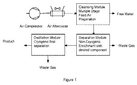
[019] Fig. 1 is a block diagram of the hybrid cryogenic gas generator with
non-cryogenic assist of the illustrated general embodiment.
[020] Fig. 2 is a schematic diagram of the hybrid cryogenic low pressure
nitrogen gas generator with non-cryogenic assist of the illustrated general
embodiment shown in Fig. 1
[021] Fig. 3 is a schematic diagram of the hybrid cryogenic high pressure
nitrogen gas generator with non-cryogenic assist of the illustrated general
embodiment shown in Fig.1.
[022] Fig. 4 is a schematic diagram of the hybrid cryogenic liquid nitrogen
generator with non-cryogenic assist of the illustrated general embodiment
shown
in Fig, 1.
[023] Fig. 5 is a schematic diagram of the hybrid cryogenic low pressure
oxygen gas generator with non-cryogenic assist of the illustrated general
embodiment shown in Figi.
[024] Fig. 6 is a schematic diagram of the hybrid cryogenic high pressure
oxygen gas generator with non-cryogenic assist of the illustrated general
embodiment shown in Fig. 1,
[025] Fig. 7 is a schematic diagram of the hybrid cryogenic liquid oxygen
generator with non-cryogenic assist of the illustrated general embodiment
shown
in Fig, 1.
[026] The invention and its various embodiments can now be better
understood by turning to the following detailed description of the preferred
embodiments which are presented as illustrated examples of the invention
defined in the claims. It is expressly understood that the invention as
defined by
4
CA 02728244 2010-12-16
WO 2009/155454 PCT/US2009/047850
the claims may be broader than the illustrated embodiments described below.
[027] Detailed Description of the Preferred Embodiments
[028] The illustrated general embodiment of the invention shown in Fig.I
is a method for producing and delivering high purity single component gas such
as nitrogen or oxygen at high pressures of up to 15,000 prig using an
apparatus
with a significantly lower profile of no more than 20 feet of overall height
than
would otherwise be required. A conventional cryogenic gas plant distillation
unit
(aka. cold box) is supplemented at the front end by using a separation module
with a non-cryogenic enrichment system not only to clean the air of water and
carbon dioxide, as is normally required by the cryogenic distillation cycle,
but
additionally, to significantly enrich the feed flow with the desired component
by
removing a significant amount of the undesired component. The removal of the
undesired component before the cryogenic process located in the distillation
module permits the distillation column to be significantly shorter than
otherwise
would be required. This in turn reduces the height of the equipment such that
it
can easily be transported and setup.
[029] The current invention comprises six main embodiments, namely a
method and apparatus for producing low pressure nitrogen gas, high pressure
nitrogen gas, liquid nitrogen, low pressure oxygen gas, high pressure oxygen
gas, and liquid oxygen.
[031] One of the preferred embodiments of the invention shown in Fig.2
is a method and apparatus that combines two technologies into a hybrid system
that can deliver high purity nitrogen gas while increasing the portability,
compact
size, and operational convenience of an on-site non-cryogenic generator.
[031] Another one of the preferred embodiments of the invention as
shown in Fig. 3 is a method and apparatus that combines three technologies
into
a hybrid system that can deliver high purity nitrogen gas at high pressures
that
are typically only achievable by pumping liquid nitrogen from delivered
liquid,
while increasing the portability, compact size, and operational convenience of
an
on-site non-cryogenic generator.
CA 02728244 2010-12-16
WO 2009/155454 PCT/US2009/047850
[032] In yet another one of the preferred embodiments of the invention
as shown in Fig. 4 is a method and apparatus that combines two technologies
into a hybrid': system that can deliver high purity liquid nitrogen that is
available
through the cryogenic process, while improving the portability, compact size,
and
operational convenience of an on-site non-cryogenic generator which cannot
produce liquid.
[033] In still another one of the preferred embodiments of the invention
as shown in Fig. 5 is a method and apparatus that combines two technologies
into a hybrid', system that can deliver high purity oxygen gas while improving
the
portability, compact size, and operational convenience of an on-site non_
cryogenic generator.
[034] In yet another one of the preferred embodiments of the invention
as shown in Fig. 6 is a method and apparatus that combines three technologies
into a hybrid'. system that can deliver high purity oxygen gas at high
pressures
that are typically only achievable by pumping liquid oxygen from delivered
liquid
while improving the portability, compact size, and operational convenience of
an
on-site non-cryogenic generator.
[035] Finally, in another one of the preferred embodiments of the
invention as shown in Fig. 7is a method and apparatus that combines two
technologies into a hybrid system that can deliver high purity liquid oxygen
that
is available through the cryogenic process while improving the portability,
compact size, and operational convenience of an on-site non-cryogenic
generator which cannot produce liquid.
[036] All the illustrated embodiments of the invention depicted in Figs.2-7
include a diesel or electric drive or engine 1 that drives an air compressor
2,
which pressurizes the air to 200 to 500 prig. The pressurized air is then
passed
through a cleansing module 3, which comprises of at least an air-to-air heat
exchanger 31, where it is cooled to near ambient temperatures; A a centrifugal
separator 32 to remove free water; a particulate filter 33 that removes
particles
and condensates down typically down to 3 microns; a coalescing filter 34,
which
removes any remaining fine oil vapor and further condensates from the air,
6
CA 02728244 2010-12-16
WO 2009/155454 PCT/US2009/047850
typically down to 0.5 microns or less; an activated carbon bed 35 which
removes
any remaining hydrocarbons and other contaminants; and a reheater 37 for the
purpose of insuring that the moisture remaining in the still saturated air
remains
in the vapor stage and does not condense on the piping or in any other
component of the apparatus. Alternatively, a water-to-air heat exchanger may
be
used in place of the air-to-air heat exchanger 31.
[037] The cleaned and prepared compressed air is then directed to a
separation module 4 comprising a temperature swing absorption system (TSA),
a pressure swing absorption system (FA), a vacuum swing absorption system
(VA), a permeable membrane array, or a combination of aforementioned
technologies which is tuned or arranged and configured to remove all remaining
water and carbon dioxide from the cleaned air, typically to less than 5 ppm
water
and less than 15 ppm carbon dioxide. The undesired component is also partially
removed as a waste gas although the separation module 4 is not optimized for
removal of the undesired component. The separation module 4 is better used for
enrichment of the flow with the desired component.
[038] The cleaned enriched air is fed to cold box 5, which comprises a
heat exchanger 51, where the enriched air is cooled by the exiting waste gas
and
the high purity product, the enriched air is then expanded in the turbo
expander
52.
[039] In the nitrogen embodiments depicted in Figs. 2-4, the enriched air
from the turbo-expander 52 is then delivered to a distillation column 53 where
final separation to the desired purity of the nitrogen is achieved and to a
evaporator-reboiler 55. The evaporator-reboiler 55 is used to liquefy the
gaseous
nitrogen which then irrigates the distillation column 53
[040] In the oxygen embodiments of the invention depicted in Figs. 5-7,
the enriched air from the turbo-expander 52 is then delivered to the bottom of
the
evaporator-reboiler 55 where it is liquefied. The liquid air is then throttled
into the
top of the distillation column 53 for final separation. Liquid oxygen collects
in the
top of evaporator-reboiler 55 where some evaporates to generate a gas flow up
through distillation column 53.
7
CA 02728244 2010-12-16
WO 2009/155454 PCT/US2009/047850
[041] In the nitrogen system embodiments of Figs. 2-4, waste gas from
the top of the evaporator-reboiler 55, or in the corresponding oxygen system
embodiments of Figs. 5-7, waste gas from the top of the distillation column
53,
is sent back to the heat exchanger 51 where it is heated by absorbing heat
from
the incoming enriched feed air as disclosed above and is then released to the
atmosphere,
[042] In the low pressure product embodiments for nitrogen in Fig. 2 and
oxygen in Fig. 5, the product from the distillation column 53 is forwarded to
the
heat exchanger 51 in a separate passage than the waste gas where it is heated
by absorbing heat from the enriched feed air as disclosed above and is then
forwarded to the final application,
[043] For generating high pressure production gas, namely for the
nitrogen embodiment in Fig.3 and the oxygen embodiment in Fig.6, the liquid
product is pressurized to the desired level by a cryogenic pump 56 which is
integral to the cold box 5. The high pressure liquid then goes to a high
pressure
version of heat exchanger 51 for vaporization and cooling of the incoming
enriched feed air, The high pressure gas that is produced is then forwarded to
the final application.
(044] For applications requiring the product to be in a liquid state, namely
nitrogen depicted in Fig.4 and oxygen depicted in Fig.', the purified product
can
be taken from the distillation column 53, bypassing the heat exchanger 51 and
forwarded to the customer for usage or storage.
(045] In the nitrogen embodiments of the invention shown in Figs. 2-4,
the PSA or TSA process normally used at the front of a cryogenic distillation
process is replaced with a permeable membrane array 4 that is selected for its
ability to remove water and carbon dioxide, and incidentally, 50% to 75% of
the
oxygen. The dry, oxygen-depleted air stream requires a much smaller heat
exchanger 51 to liquefy and smaller distillation column 53 to achieve the high
purity (9,99% -- 99.999% by volume) nitrogen desired. This smaller heat
exchanger 51 and distillation column 53 make the overall system much smaller
and easier to transport and setup as compared to a conventional cryogenic gas
8
CA 02728244 2010-12-16
WO 2009/155454 PCT/US2009/047850
plant. For example, the entire system 10 can be installed in a conventional 20
foot shipping container, laying distillation column 53 lengthwise in the
container,
and then upending the container for operation.
[046] Another aspect of the present invention is the capability of
delivering very high pressures, such as are typically only achieved in a
liquid
nitrogen or liquid oxygen pumping system. A standard cryogenic gas plant
design takes the low pressure liquid nitrogen or oxygen that comes off the
distillation column and passes it through a heat exchanger counter-flow with
the
incoming air. This serves to warm the newly generated nitrogen or oxygen and
starts to cool the incoming air, recovering a significant portion of the
refrigeration.
The present invention places a high pressure liquid pump 56 in the circuit
before
the last pass through the heat exchanger 51 in Figs. 3 and 6. This pump 56
raises the pressure of the liquid as high as 10,000 to 15,000 prig. Such high
pressures are not achievable in a conventional on-site P SA or membrane based
nitrogen or oxygen generation system. The high pressure liquid is then
vaporized in the special high pressure version of heat exchanger 51 designed
for
this purpose.
[047] In summary, the illustrated embodiment of the invention includes an
apparatus for high purity extraction of a selected component from air
comprising:.
a source of air; a cleaning module arranged coupled to the source of air and
configured to preferentially remove carbon dioxide and water from the air; a
non-
cryogenic enrichment module coupled to the cleaning module to preferentially
extract the selected component to produce a cleaned modified air mixture
enriched in the selected component; and a liquefaction-distillation unit
coupled to
the enrichment module for liquefying the air mixture enriched in the selected
component and separating the selected component from the modified air mixture
to provide high purity liquid phase extraction of the selected component. Due
to
the enrichment before distillation., the liquefaction-distillation unit may
thus
comprise a shortened liquefaction-distillation column, which can be
advantageous operated on a portable or moving platform, ship or vehicle. The
selected component is nitrogen or oxygen.
9
CA 02728244 2010-12-16
WO 2009/155454 PCT/US2009/047850
[048] More specifically, the illustrated embodiment includes a nitrogen
plant for generating high purity nitrogen to an application comprising: a
source of
air including nitrogen and oxygen; a non-cryogenic separation module coupled
to the source of air, the separation module arranged and configured to
preferentially remove carbon dioxide and water from the air but also a portion
of
the oxygen; and a liquefaction-distillation unit coupled to the separation
module
for liquefying the nitrogen rich air produced by the non-cryogenic separation
module and:: separating the oxygen from the nitrogen to produce high purity
liquid
nitrogen.
[049] The plant further comprises a heat exchanger coupled to the
liquefaction-distillation unit for vaporizing the high purity liquid nitrogen
into a low
pressure nitrogen gas.
[050] The plant further comprises a pump coupled between the
liquefaction-distillation unit and the heat exchanger for pressurizing the
produced
high purity liquid'. nitrogen wherein the heat exchanger is a high pressure
heat
exchanger, and wherein the liquid nitrogen output from the liquefaction-
distillation unit is pumped at high pressure by the pump through the high
pressure heat exchanger to deliver high pressure nitrogen gas from the high
pressure heat exchanger.
[051] The plant further comprises a multiple stage feed air preparation
unit coupled between the source of air and the separation module to clean the
air
for delivery to the separation module.
[852] The separation module in one embodiment is a molecular sieve
type non-cryogenic gas separation system selected for its ability to remove
water
and carbon dioxide and oxygen from the air.
[053] The separation module in another embodiment is a
membrane array selected for its ability to remove water and carbon dioxide and
oxygen from the air.
[054] The illustrated embodiment of the invention also includes a method
for high purity extraction of a selected component from air comprising the
steps
of preferentially removing carbon dioxide and water from air to provide
cleaned
CA 02728244 2010-12-16
WO 2009/155454 PCT/US2009/047850
air, non-cryogenically enriching the cleaned air in the selected component; to
provide an enriched modified air mixture, liquefying enriched modified air
mixture,
and fractionally distilling the liquefied modified air mixture to
preferentially extract
the selected component at high purity in liquid phase. Again due to the step
of
enriching before fractionally distilling, the fractional distillation may be
performed
in a shortened column or over a shorter vertical distance, which is an
advantage
when performed on a portable or moving platform, ship or vehicle. The step of
fractionally distilling the liquefied modified air mixture to preferentially
extract the
selected component at high purity in liquid phase comprises producing high
purity liquid' nitrogen or oxygen.
[055] The illustrated embodiment of the invention thus also includes a
method for generating high purity nitrogen to an application comprising the
steps
of providing a flow of air, removing carbon dioxide, water, and a portion of
the
oxygen from the compressed air to form a nitrogen rich gas, liquefying the
nitrogen rich gas, and separating the remaining oxygen from the nitrogen rich
liquid in a fractional distillation column to produce a high purity liquid
nitrogen.
[056] The method further comprises vaporizing the high purity liquid
nitrogen in a heat exchanger to produce a high purity low pressure nitrogen
gas.
(057] The method further comprises pressurizing of the high purity liquid
nitrogen and vaporizing the high purity high pressure liquid nitrogen in a
high
pressure heat exchanger to produce a high purity high pressure nitrogen gas.
[058] The method further comprises cleaning the air prior to removing
carbon dioxide, water, and a portion of the oxygen from the flow of air.
[059] The illustrated embodiment of the invention thus also includes an
oxygen plant for generating high purity oxygen to an application comprising: a
source of air including nitrogen and oxygen; a non-cryogenic separation module
coupled to the source of air, the separation module arranged and configured to
preferentially remove carbon dioxide and water from the air but also a portion
of
the nitrogen; a liquefaction-distillation unit coupled to the non-cryogenic
separation module for liquefying the oxygen rich air produced by the non-
11
CA 02728244 2010-12-16
WO 2009/155454 PCT/US2009/047850
cryogenic separation module and separating the nitrogen from the oxygen to
produce high purity liquid oxygen.
[060] The plant further comprises a heat exchanger coupled to the
liquefaction-distillation unit for vaporizing the high purity liquid oxygen
into a low
pressure oxygen gas.
[061] The plant further comprises a pump coupled between the
liquefaction-distillation unit and the heat exchanger for pressurizing the
produced
high purity liquid, oxygen wherein the heat exchanger is a high pressure heat
exchanger, and wherein the liquid oxygen output from the liquefaction-
distillation
unit is pumped' to a high pressure by the pump through the high pressure heat
exchanger to deliver high pressure oxygen gas from the high pressure heat
exchanger.
[062] The plant further comprises a multiple stage feed air preparation
unit coupled between the source of air and the separation module to clean the
air
for delivery to the separation module,
[063] The separation module in one embodiment is a molecular sieve
type non-cryogenic gas separation system selected for its ability to remove
water, carbon dioxide and nitrogen from the air.
(064] The illustrated embodiment of the invention thus also includes a
method for generating high purity oxygen to an application comprising the
steps
of providing a flow of air, removing carbon dioxide, water, and a portion of
the
nitrogen from the compressed air to form a oxygen rich gas, liquefying the
oxygen rich gas, and separating the remaining nitrogen from the oxygen rich
liquid in a fractional distillation column to produce a high purity liquid
oxygen.
[065] The method further comprises vaporizing the high purity liquid
oxygen in a heat exchanger to produce a high purity low pressure oxygen gas.
[066] The method further comprises pressurizing of the high purity liquid
oxygen and vaporizing the high purity high pressure liquid oxygen in a high
pressure heat exchanger to produce a high purity high pressure oxygen gas.
[067] The method further comprises cleaning the air prior to removing
carbon dioxide, water, and apportion of the nitrogen from the flow of air.
12
CA 02728244 2010-12-16
WO 2009/155454 PCT/US2009/047850
[068] Many alterations and modifications may be made by those having
ordinary skill in the art without departing from the spirit and scope of the
invention. Therefore, it must be understood that the illustrated embodiment
has
been set forth only for the purposes of example and that it should not be
taken as
limiting the invention as defined by the following invention and its various
embodiments.
[069] Therefore, it must be understood that the illustrated embodiments
have been set forth only for the purposes of example and that it should not be
taken as limiting the invention as defined by the following claims. For
example,
notwithstanding the fact that the elements of a claim are set forth below in a
certain combination, it must be expressly understood that the invention
includes
other combinations of fewer, more or different elements, which are disclosed
in
above even when not initially claimed in such combinations. A teaching that
two
elements are combined in a claimed combination is further to be understood as
also allowing for a claimed combination in which the two elements are not
combined with each other, but may be used alone or combined in other
combinations. The excision of any disclosed element of the invention is
explicitly
contemplated as within the scope of the invention.
(070] The words used in this specification to describe the invention and
its various embodiments are to be understood not only in the sense of their
commonly defined meanings, but to include by special definition in this
specification structure, material or acts beyond the scope of the commonly
defined meanings. Thus if an element can be understood in the context of this
specification as including more than one meaning, then its use in a claim must
be
understood as being generic to all possible meanings supported by the
specification and by the word itself.
[071] The definitions of the words or elements of the following claims are,
therefore, defined in this specification to include not only the combination
of
elements which are literally set forth, but all equivalent structure, material
or acts
for performing substantially the same function in substantially the same way
to
obtain substantially the same result. In this sense it is therefore
contemplated
13
CA 02728244 2010-12-16
WO 2009/155454 PCT/US2009/047850
that an equivalent substitution of two or more elements may be made for any
one
of the elements in the claims below or that a single element may be
substituted
for two or more elements in a claim. Although elements may be described above
as acting in certain combinations and even initially claimed as such, it is to
be
expressly understood that one or more elements from a claimed combination can
in some cases be excised from the combination and that the claimed
combination may be directed to a subcombination or variation of a
subcombination.
(072] Insubstantial changes from the claimed subject matter as viewed by
a person with ordinary skill in the art, now known or later devised, are
expressly
contemplated as being equivalently within the scope of the claims. Therefore,
obvious substitutions now or later known to one with ordinary skill in the art
are
defined to be within the scope of the defined elements.
[073] The claims are thus to be understood to include what is specifically
illustrated and described above, what is conceptionally equivalent, what can
be
obviously substituted and also what essentially incorporates the essential
idea of
the invention.
14