Language selection

Search

Patent 2728621 Summary

Third-party information liability

Some of the information on this Web page has been provided by external sources. The Government of Canada is not responsible for the accuracy, reliability or currency of the information supplied by external sources. Users wishing to rely upon this information should consult directly with the source of the information. Content provided by external sources is not subject to official languages, privacy and accessibility requirements.

Claims and Abstract availability

Any discrepancies in the text and image of the Claims and Abstract are due to differing posting times. Text of the Claims and Abstract are posted:

  • At the time the application is open to public inspection;
  • At the time of issue of the patent (grant).
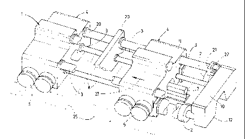
(12) Patent: (11) CA 2728621
(54) English Title: WELDING UNIT FOR WELDING RAILS OF A TRACK
(54) French Title: UNITE DE SOUDAGE DESTINEE A SOUDER LES RAILS D'UNE VOIE
Status: Granted and Issued
Bibliographic Data
(51) International Patent Classification (IPC):
  • E01B 29/46 (2006.01)
  • B23K 11/00 (2006.01)
(72) Inventors :
  • THEURER, JOSEF (Austria)
  • LICHTBERGER, BERNHARD (Austria)
  • MUEHLLEITNER, HEINZ (Austria)
(73) Owners :
  • FRANZ PLASSER BAHNBAUMASCHINEN-INDUSTRIEGESELLSCHAFT MBH
(71) Applicants :
  • FRANZ PLASSER BAHNBAUMASCHINEN-INDUSTRIEGESELLSCHAFT MBH (Austria)
(74) Agent: RICHES, MCKENZIE & HERBERT LLP
(74) Associate agent:
(45) Issued: 2016-05-24
(86) PCT Filing Date: 2009-07-09
(87) Open to Public Inspection: 2010-02-11
Examination requested: 2014-03-12
Availability of licence: N/A
Dedicated to the Public: N/A
(25) Language of filing: English

Patent Cooperation Treaty (PCT): Yes
(86) PCT Filing Number: PCT/EP2009/004972
(87) International Publication Number: WO 2010015309
(85) National Entry: 2010-12-20

(30) Application Priority Data:
Application No. Country/Territory Date
A 1207/2008 (Austria) 2008-08-04

Abstracts

English Abstract


A welding unit (1) for welding rails (7) of a track comprises two unit bodies
(4)
which are movable towards one another by means of displacement cylinders (2)
along guides (3) extending parallel to the rails (7). The displacement
cylinders
(2) are fastened, on the one hand, to pull rods (8) and, on the other hand, to
a
crossbeam (12). This enables a structurally simple embodiment with strong
pulling forces.


French Abstract

Linvention concerne une unité de soudage (1) destinée à souder les rails (7) dune voie comprenant deux corps dunité (4) pouvant être déplacés lun par rapport à lautre, le long de guides dunité (3) sétendant parallèlement aux rails (7), par des cylindres de déplacement (2). Les cylindres de déplacement (2) sont reliés dune part à des barres de traction (8) et dautre part à une traverse (12). Cela permet dobtenir une construction simple à forces de traction élevées.

Claims

Note: Claims are shown in the official language in which they were submitted.

5
We Claim
1. A welding unit for welding rails (7) of a track, including a first and a
second
unit body (4), each connected to a clamping drive (5) having a respective
piston
rod (18), which are movable towards one another by means of displacement
cylinders (2) along guides (3) extending parallel to the rails (7), and
including a
crossbeam (12) - connected to the guides (3) and the displacement cylinders
(2) -
as well as pull rods (8) extending parallel to the guides (3) and connected to
the
crossbeam (12), and wherein longitudinal axes (13, 14, 15) of the pull rods
(8),
and of the displacement cylinders (2) and clamping drives (5) are positioned
in a
common plane (16).
2. A welding unit according to claim 1, characterized in that the common
plane (16) is positioned in a neutral axis (17) of the rails (7) to be welded.
3. A welding unit according to claim 1, characterized in that longitudinal
axes
(15) of the clamping drives (5) arranged on each unit body (4) are positioned
in
the common plane (16) and in a position extending perpendicularly to the
longitudinal axis (13) of the pull rods (8), wherein a piston rod (18) of the
clamping drive (5) has an opening (19) for passage of the pull rod (8).
4. A welding unit according to claim 1, characterized in that each guide
(3) is
connected to the crossbeam (12) by means of an articulated connection (22).

Description

Note: Descriptions are shown in the official language in which they were submitted.


CA 02728621 2016-01-13
1
WELDING UNIT FOR WELDING RAILS OF A TRACK
SCOPE OF THE INVENTION
[0001] The invention relates to a welding unit for welding rails of a track,
with a
first and a second unit body, each connected to a clamping drive, which
are movable towards one another by means of displacement cylinders
along guides extending parallel to the rails.
BACKGROUND OF THE INVENTION
[0002] Welding units of this type for so-called mobile flash-butt welding have
already become known in various embodiments from a multitude of
publications, such as, for example, US 3,349,216 or GB 2 185 703 A.
[0003] A further welding unit is known in EP 0 132 227 B1, in which the two
unit bodies are connected to one another by means of a toggle lever.
The displacement cylinders are connected to a crossbeam on which
clamping drives for gripping the rail are provided.
SUMMARY OF THE INVENTION
[0004] It is the object of the present invention to provide a welding unit of
the
type mentioned at the beginning which ¨ while designed with structural
simplicity ¨ can transmit to the rail especially strong pulling forces
directed in the longitudinal direction of the rail.
[0005] According to the invention, the object is achieved with a welding unit
of
the specified kind by means of various features described herein.
[0006] By positioning the displacement cylinders in this way, the welding unit
can be formed with minimal structural height. This enables a
cantilevered suspension on a rail vehicle without thereby impeding view
of the track as prescribed by UIC. Furthermore, it is possible due to this
embodiment to pull the rail closer by extending the piston rod out from
the displacement cylinder. Thus, the piston surface is not reduced by the
piston rod and is available to the full extent for the pressure build-up.
Further, the displacement cylinders can have a relatively small diameter
while still maintaining strong pulling forces. This results in the advantage
that the rail ends to be welded need only be lifted slightly from the
sleepers, thus facilitating a flush alignment of the rail ends.

CA 02728621 2016-01-13
0 = =
2
Accordingly, in one aspect the present invention resides in a welding
unit for welding rails of a track, including a first and a second unit body,
each connected to a clamping drive having a respective piston rod,
which are movable towards one another by means of displacement
cylinders along guides extending parallel to the rails, and including a
crossbeam - connected to the guides and the displacement cylinders -
as well as pull rods extending parallel to the guides and connected to
the crossbeam, and wherein longitudinal axes of the pull rods, - and of
the displacement cylinders and clamping drives are positioned in a
common plane.
[0007] Additional advantages of the invention become apparent from the
following
description and drawings.
DESCRIPTION OF THE DRAWINGS
[0008] The invention will be described in more detail below with reference to
an
embodiment represented in the drawing in which
[0009] Fig. 1 is a perspective view of a welding unit, wherein ¨ for the sake
of clarity
¨ only the most important components are shown,
[0010] Figs. 2 and 3 are a top view and side view, respectively, of the
welding
unit visible in Fig. 1, and
[0011] Fig. 4 is a view of a unit body in the longitudinal direction of the
rail.
DETAILED DESCRIPTION OF THE PREFERRED EMBODIMENTS
[0012] A welding unit 1, shown in Figs. 1 to 3, is composed of two unit bodies
4 which are displaceable towards one another along guides 3 with the
aid of displacement cylinders 2. The unit bodies 4 are connected in
each case to two clamping drives 5 by means of which

CA 02728621 2015-08-11
3
clamping jaws 6 are pressed against rails 7 to be welded to one
another.
[0013] Pull rods 8, extending parallel to the guides 3, have a first end 9
fastened to the first unit body 4 and are guided through the second
unit body 4, wherein a respective second end 10 is positioned to
protrude with regard to an exterior surface 11, extending
perpendicularly to the guides 3, of the second unit body 4.
[0014] The second ends 10 of the two pull rods 8 are connected to a
crossbeam 12. Each displacement cylinder 2 is fastened, on the one
hand, to the said exterior surface 11 of the second unit body 4 and,
on the other hand, to the crossbeam 12.
[0015] As visible particularly in Fig. 3, longitudinal axes 13, 14, 15 of the
pull
rods 8, of the displacement cylinders 2 and of the clamping drives 5
are positioned in a common plane 16. The latter is situated in a
neutral axis 17 of the rail 7.
[0016] As shown in Fig. 4, the clamping drives 5 - extending perpendicularly
to the longitudinal axis 13 of the pull rods 8 - are each equipped, in
the region of piston rods 18, with an opening 19 for passage of the
pull rod 8. The guides 3, having a first end 20 connected to the first
unit body 4, have a second end 21 connected in each case to the
crossbeam 12 by means of an articulated connection 22.

CA 02728621 2015-08-11
4
[0017] A shearing device 23 for removing a welding seam is provided
between the two unit bodies 4. Fastened to each exterior surface 11
of the two unit bodies 4 is a lifting device 24 for lifting the rails 7.
[0018] In preparation of the welding process, both rails 7 are lifted from the
sleepers 25, lying thereunder, by means of the lifting devices 24 (see
Fig. 4) and pressed against stop bars 26. Subsequently, the clamping
drives 5 are actuated in order to press the clamping jaws 6 against a
rail web of the rail 7 with a clamping force of 350 tons. Additionally,
electrodes (not shown) are pressed against the rails 7.
[0019] To initiate the welding process, the second unit body 4 together with
the gripped rail 7 is moved, by actuation of the displacement drives 2,
with a pulling force of up to 150 tons in a direction 27 towards the
second rail 7. As soon as the spacing of the two rail ends as required
for the welding has been achieved, the supply of electrical current is
started.
[0020] In case that the ambient temperature lies above the neutral
temperature, it is also possible, if desired, to move the rail 7 ¨ by
corresponding actuation of the two displacement drives 2 ¨ in a
direction opposite to the indicated direction 28.

Representative Drawing
A single figure which represents the drawing illustrating the invention.
Administrative Status

2024-08-01:As part of the Next Generation Patents (NGP) transition, the Canadian Patents Database (CPD) now contains a more detailed Event History, which replicates the Event Log of our new back-office solution.

Please note that "Inactive:" events refers to events no longer in use in our new back-office solution.

For a clearer understanding of the status of the application/patent presented on this page, the site Disclaimer , as well as the definitions for Patent , Event History , Maintenance Fee  and Payment History  should be consulted.

Event History

Description Date
Maintenance Request Received 2024-06-12
Maintenance Request Received 2023-06-13
Maintenance Request Received 2022-06-10
Maintenance Request Received 2021-06-08
Inactive: COVID 19 - Deadline extended 2020-07-02
Maintenance Request Received 2020-06-16
Common Representative Appointed 2019-10-30
Maintenance Request Received 2019-06-14
Maintenance Request Received 2018-06-06
Maintenance Request Received 2017-06-09
Maintenance Request Received 2016-06-06
Grant by Issuance 2016-05-24
Inactive: Cover page published 2016-05-23
Pre-grant 2016-03-15
Inactive: Final fee received 2016-03-15
Notice of Allowance is Issued 2016-02-16
Letter Sent 2016-02-16
Notice of Allowance is Issued 2016-02-16
Inactive: Q2 passed 2016-02-10
Inactive: Approved for allowance (AFA) 2016-02-10
Amendment Received - Voluntary Amendment 2016-01-13
Inactive: S.30(2) Rules - Examiner requisition 2015-09-14
Inactive: Report - No QC 2015-09-10
Amendment Received - Voluntary Amendment 2015-08-24
Amendment Received - Voluntary Amendment 2015-08-11
Inactive: Office letter - PCT 2015-07-16
Maintenance Request Received 2015-06-12
Maintenance Request Received 2014-06-13
Letter Sent 2014-03-20
Request for Examination Requirements Determined Compliant 2014-03-12
All Requirements for Examination Determined Compliant 2014-03-12
Request for Examination Received 2014-03-12
Maintenance Request Received 2013-06-10
Inactive: Cover page published 2011-02-25
Inactive: Notice - National entry - No RFE 2011-02-09
Inactive: First IPC assigned 2011-02-07
Application Received - PCT 2011-02-07
Inactive: IPC assigned 2011-02-07
National Entry Requirements Determined Compliant 2010-12-20
Application Published (Open to Public Inspection) 2010-02-11

Abandonment History

There is no abandonment history.

Maintenance Fee

The last payment was received on 2015-06-12

Note : If the full payment has not been received on or before the date indicated, a further fee may be required which may be one of the following

  • the reinstatement fee;
  • the late payment fee; or
  • additional fee to reverse deemed expiry.

Please refer to the CIPO Patent Fees web page to see all current fee amounts.

Owners on Record

Note: Records showing the ownership history in alphabetical order.

Current Owners on Record
FRANZ PLASSER BAHNBAUMASCHINEN-INDUSTRIEGESELLSCHAFT MBH
Past Owners on Record
BERNHARD LICHTBERGER
HEINZ MUEHLLEITNER
JOSEF THEURER
Past Owners that do not appear in the "Owners on Record" listing will appear in other documentation within the application.
Documents

To view selected files, please enter reCAPTCHA code :


To view images, click a link in the Document Description column. To download the documents, select one or more checkboxes in the first column and then click the "Download Selected in PDF format (Zip Archive)" or the "Download Selected as Single PDF" button.

List of published and non-published patent-specific documents on the CPD .

If you have any difficulty accessing content, you can call the Client Service Centre at 1-866-997-1936 or send them an e-mail at CIPO Client Service Centre.


Document
Description 
Date
(yyyy-mm-dd) 
Number of pages   Size of Image (KB) 
Description 2010-12-20 4 130
Claims 2010-12-20 2 48
Drawings 2010-12-20 3 71
Abstract 2010-12-20 1 11
Representative drawing 2010-12-20 1 29
Cover Page 2011-02-25 1 49
Description 2015-08-11 4 129
Claims 2015-08-11 2 31
Drawings 2015-08-11 3 72
Claims 2015-08-24 2 32
Description 2016-01-13 4 136
Claims 2016-01-13 1 29
Representative drawing 2016-04-05 1 19
Cover Page 2016-04-05 1 48
Maintenance fee payment 2024-06-12 1 66
Notice of National Entry 2011-02-09 1 194
Reminder - Request for Examination 2014-03-11 1 118
Acknowledgement of Request for Examination 2014-03-20 1 176
Commissioner's Notice - Application Found Allowable 2016-02-16 1 160
Maintenance fee payment 2023-06-13 1 57
PCT Correspondence 2023-07-21 25 878
PCT 2010-12-20 3 141
Fees 2012-06-13 1 55
Fees 2013-06-10 1 53
Fees 2014-06-13 1 53
Maintenance fee payment 2015-06-12 1 53
Correspondence 2015-07-16 1 36
Amendment / response to report 2015-08-11 11 297
Amendment / response to report 2015-08-24 4 71
Examiner Requisition 2015-09-14 4 245
Amendment / response to report 2016-01-13 8 273
Final fee 2016-03-15 1 54
Maintenance fee payment 2016-06-06 1 53
Maintenance fee payment 2017-06-09 1 54
Maintenance fee payment 2018-06-06 1 54
Maintenance fee payment 2019-06-14 1 53
Maintenance fee payment 2020-06-16 2 73
Maintenance fee payment 2021-06-08 1 52
Maintenance fee payment 2022-06-10 1 55