Note: Descriptions are shown in the official language in which they were submitted.
CA 02728840 2011-01-19
ACCESS APPARATUS INCLUDING INTEGRAL ZERO-CLOSURE VALVE AND
CHECK VALVE
BACKGROUND
Technical Field
[0002] The present disclosure relates to an access apparatus and, more
particularly, to an
access apparatus that includes an integral zero-closure valve and check valve
for an insufflation
port.
Description of Related Art
[0003] In laparoscopic procedures, clinicians perform surgery in the interior
of the
abdomen through a small incision, and in endoscopic procedures, clinicians
conduct surgery in
any hollow viscus of the body through a narrow tube or cannula inserted
through a small
entrance incision in the skin. In certain instances, one or more insufflation
ports are operably
associated with the narrow tube or cannula and are configured to provide a
pressurized gas, e.g.,
C02, into the abdomen after the narrow tube or cannula is inserted into the
incision and secured
to a patient, thus creating a pneumoperitoneum. The gas provides a positive
pressure that raises
the inner body wall away from internal organs, thereby providing the surgeon
with an operating
space. By creating the operating space, the clinician avoids unnecessarily
contacting the organs
with the instruments inserted through the cannula assembly,
1
CA 02728840 2011-01-19
[0004] Typically, the one or more insufflation ports include one or more
components,
such as, for example, intricate manual valves, caps, stopcocks, external tubes
and the like, that
are configured to maintain the pneumoperitoneum and control for insufflation
gas flow. As can
be appreciated, the aforementioned components, e.g., intricate valves,
increase the cost of
manufacture of the insufflation port and/or access apparatus.
[0005] Accordingly, it may prove advantageous to provide an access apparatus
that
includes an easy to manufacture component that is configured to maintain the
pneumoperitoneum and control for insufflation gas flow.
SUMMARY
[0006] The present disclosure provides an access apparatus for use in surgical
procedures. The access apparatus includes an access member that defines a
longitudinal axis and
has a longitudinal passage that provides entry to an abdominal cavity of a
patient. The
longitudinal passage is adapted to permit passage of a surgical instrument
utilized in performing
a surgical procedure. A housing includes a proximal end defining an opening in
communication
with the longitudinal passage of the access member to permit passage of the
surgical instrument.
A zero-closure valve is disposed within the housing and adjacent the
longitudinal passage. The
zero-closure valve is configured to provide a substantially fluid-tight seal
in the absence of the
surgical instrument inserted therethrough. A check-valve is operably
associated with the zero-
closure valve and is in fluid communication with the longitudinal passage and
an insufflation
port operably associated with the access member. The check-valve is configured
to provide a
fluid-tight seal when a pressure inside the access apparatus is greater than a
pressure external
thereof
2
CA 02728840 2011-01-19
[0007] The present disclosure provides a zero closure valve that is adapted to
connect to
an access apparatus configured to provide access into an abdominal cavity of a
patient. A check-
valve is operably associated with the zero-closure valve and is in fluid
communication with a
longitudinal passage associated with an access member of the access apparatus
and an
insufflation port operably associated with the access member. The check-valve
is configured to
provide a fluid-tight seal when a pressure inside the access apparatus is
greater than a pressure
external thereof,
BRIEF DESCRIPTION OF THE DRAWINGS
[0008] Various embodiments of the present disclosure are described herein with
reference to the drawings wherein:
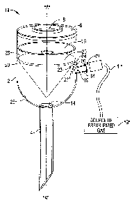
[0009] FIG. 1 is a perspective view of an access apparatus including an
integral zero-
closure valve and check valve according to an embodiment of the present
disclosure;
[0010] FIG. 2 is a side cross-sectional view of a proximal end of the access
apparatus
depicted in FIG. 1; and
[0011] FIG. 3 is a side cross-sectional view of a proximal end of the access
apparatus
according to an alternate embodiment of the present disclosure.
DETAILED DESCRIPTION
[0012] The access apparatus of the present disclosure provides a substantially
fluid-tight
seal between a body cavity of a patient and the outside atmosphere. The access
apparatus of the
present disclosure is configured to receive surgical instruments of varying
diameters. Included
3
CA 02728840 2011-01-19
among the various procedures contemplated by the present disclosure are
endoscopic,
laparoscopic, arthroscopic, orthopedic, etc.
100131 The access apparatus of the present disclosure contemplates the
introduction of
various types of instrumentation during the particular procedure. Examples of
instrumentation
include, but are not limited to, clip appliers, graspers, dissectors,
retractors, staplers, laser probes,
photographic devices, endoscopes and laparoscopes, tubes, anchors, anchor
drives, etc. Such
instruments will collectively be referred to as "instruments" or
"instrumentation" or "surgical
objects."
[0014] In the following description, as is traditional, the term "proximal"
refers to the
portion of the device closer to the operator while the tern "distal" refers to
the portion of the
device farther from the operator.
[0015] With reference to FIGS. 1 and 2, and initially with reference to FIG. 1
an access
apparatus 10 is shown. Access apparatus 10 and operative components associated
therewith may
be formed from any suitable material, e.g., a biocornpatible material that is
made from an
elastomeric material. Access apparatus 10 defines a longitudinal axis "A" and
includes a
housing 2 and an access member 4. A proximal end 6 of housing 2 includes an
opening 8 and
access member 4 defines a longitudinal passageway 14. Opening 8 and
longitudinal passageway
14 are generally aligned with respect to the longitudinal axis "A" to permit
passage of surgical
objects such as instruments "I" (FIG. 2) utilized in connection with the
procedure.
[0016] An insufflation port 18 of suitable proportion is operably coupled to
the housing 2
via one or more suitable coupling methods including but not limited to a press
fit or friction fit
connection, soldering brazing, welding etc. In the illustrated embodiment,
insufflation port 18 is
monolithically formed with the housing 2. The insufflation port 18 serves as
an intermediary
4
CA 02728840 2011-01-19
interface that provides fluid communication between the access apparatus 10
and a source of
insufflation gas "G." More particularly, a distal end of a hose "H" is
operably coupled to the
source of pressurized gas "G" and a proximal end of the hose "H" operably
couples to the access
apparatus 10 via one or more suitable coupling methods, e.g., a Luer type
fitting or the like. In
certain instances, the source of pressurized gas may be directly coupled, via
a syringe, to the
insufflation port 18. Insufflation port 18 includes open proximal and distal
ends 19 and 21,
respectively, that are of suitable proportion.
100171 Access apparatus 10 includes a duck bill or zero-closure valve 20 that
is disposed
within the housing 2 and adjacent the longitudinal passageway 14. More
particularly, zero-
closure valve 20 securely affixes to an interior wall 25 of the housing 2 by
known fixation
methods. In one particular embodiment, the zero-closure valve 20 includes a
generally circular
flange 23 (FIG. 1) that rests upon a corresponding ledge or shelf 29, as best
seen in FIG. 2, that is
operably disposed on the interior wall 25 of the housing 2. More particularly,
the ledge 29
substantially extends along a circumference of the interior wall 25 of the
housing 2. In the
illustrated embodiment, a gap or break in the ledge 29 is disposed adjacent
the flange 23 of the
zero-closure valve 20. In an assembled configuration, flange 23 rests on the
ledge 29 such that
the zero-closure valve 20 is maintained in a substantially fixed position.
Zero-closure valve 20
tapers distally and inwardly to a sealed configuration, as best seen in FIG.
1. As such, zero-
closure valve 20 is configured to provide a substantially fluid-tight seal in
the absence of a
surgical instrument "I" inserted therethrough, as is conventional in the art.
[0018] A check-valve 22 portion (check-valve 22) is operably associated with
the zero-
closure valve 20 and is configured to provide a fluid-tight seal when a
pressure inside the access
apparatus is greater than a pressure external thereof (FIGS. I and 2). In the
illustrated
CA 02728840 2011-01-19
embodiment, check-valve 22 is integrally formed with the zero-closure valve
20. More
particularly, the check-valve 22 is monolithically formed with the zero-
closure valve 20. In the
illustrated embodiment, the check-valve 22 is operably disposed adjacent the
flange 23 and the
gap or break associated with the ledge 29. It should be recognized that while
the present
invention is illustrated and described herein as having the check valve 22 be
associated with,
e.g., formed as a single piece with, the zero-closure valve 20, other
embodiments are
contemplated in which the check valve 22 is associated with, e.g., formed as a
single piece with,
components of the access apparatus 10 other than the zero-closure valve 20.
For example, in
other embodiments, the check valve 22 may be associated with, e.g., formed as
a single piece
with, the instrument seal 16. However, having the check valve 22 be associated
with, e.g.,
formed as a single piece with, the zero-closure valve 20 may have the
advantage that insufflation
fluid is introduced at a point that is distal relative to any seals/valves,
thereby permitting the free
flow of such insufflation fluid irrespective of whether such seals/valves are
in the open or closed
positions and irrespective of whether an instrument is present therein.
[00191 Check-valve 22 includes a generally elongated or "flapper" portion 26
(flapper
26) that is dimensioned to substantially, if not entirely, cover the open
proximal end 19 of the
insufflation port 18 when the flapper 26 is pressed against the interior wall
25 of the housing 2
adjacent the open proximal end 19 of the insufflation port 18. In an assembled
configuration, the
flapper 26 is positioned within the gap or break associated with the ledge 29.
Positioning the
flapper 26 within the gap or break assists in providing a fluid-tight seal
when the flapper 26 is
pressed against the interior wall 25 of the housing 2. Flapper 26 is
configured to move radially
inward (shown in phantom in FIGS. 1 and 2) when a pressure outside the access
apparatus 10 is
greater than a pressure inside the access apparatus 10. To this end, flapper
26 maybe coupled to
6
CA 02728840 2011-01-19
the zero-closure valve 20 via one or more suitable hinge interfaces and/or
configurations. In the
embodiment shown in FIG. 1, a hinge portion 24 couples the flapper 26 to the
zero-closure valve
20. In this embodiment, the hinge portion 24 is made from the same elastomeric
material from
which the zero-closure valve 20 and flapper 26 are made, e.g., the zero-
closure valve 20 and
flapper 26 are monolithically/integrally formed such that the hinge portion 24
is merely a region
of material between the zero-closure valve 20 and flapper 26 which acts as a
hinge when the
flapper 26 is moved relative to the zero-closure valve 20, e.g., it is a
living hinge.
[0020] Alternatively, as shown in FIG. 2, the hinge portion 24 or portions
thereof may be
made from a material that is different from the material from which the zero-
closure valve 20
and/or the flapper 26 are made. For example, in certain embodiments, the hinge
portion 24 may
incorporate a hinge pin and may be made from a material, e.g., an elastomeric
material, that is
more or less rigid (e.g., to achieve a desired radially flexing or moving of
the flapper portion 26
for a given amount of change in pressure" AP) than the elastomeric material
from which the
zero-closure valve 20 and/or flapper 26 are made.
[0021] In embodiments, a resilient member may be operably associated with the
zero-
closure valve 20 and/or check-valve 22 (FIG. 3). For example, a spring 27 may
be operably
associated with the check-valve to assist in maintaining a fluid-tight seal
when a pressure inside
the access apparatus is greater than a pressure external thereof. The spring
27 may be any
suitable spring known in the art including, but not limited to a leaf spring,
a torsion spring, a coil
spring, etc. In the embodiment illustrated in FIG. 3, the spring 27 is a
torsion spring 27 that is
operably coupled to the flapper 26 and a portion of the zero-closure valve 20.
[0022] In certain embodiments, the access apparatus 101nay include one or more
instrument seals 16 (see FIGS. 1 and 2, for example) disposed within the
housing 2 and adjacent
7
CA 02728840 2011-01-19
longitudinal passageway 14 and in mechanical cooperation with housing 2.
Instrument seal 16 is
configured to create a substantially fluid-tight seal around an instrument "I"
introduced through
the seal 16. One suitable instrument seal is disclosed in commonly assigned
U.S. Patent No.
6,702,787 to Racenet, the entire contents of which disclosure is incorporated
by reference herein.
[0023] From the foregoing and with reference to the various figure drawings,
those
skilled in the art will appreciate that certain modifications can also be made
to the present
disclosure without departing from the scope of the same. For example, flapper
26 may include a
raised portion 30, e.g., a detent 30, which is configured and proportioned to
"plug" the open
proximal end 19 of the insufflation port 18 when the flapper 26 is pressed
against the interior
wall of the housing 2. Additionally or alternatively, the proximal end 19 of
the insufflation port
18 may have a shape, e.g., sloped surfaces, that are configured to engage the
raised portion 30 of
the flapper 26 and thereby receive the detent 30. For illustrative purposes,
the detent 30 is shown
in phantom. Detent 30 assists in maintaining the flapper 26 and opening 19 in
a fluid-tight
sealed engagement with each other, when sealing therebetween is desired. More
particularly, the
integrity of the fluid-tight seal between the flapper 26 and insufflation port
18 maybe increased
because of the configuration of flapper 26 and detent 30. That is, the detent
30 "plugs" the open
proximal end 19 of the insufflation port 18.
[0024] It should be recognized that, in alternative embodiments, the detent 30
may be
located on or adjacent to the proximal end 19 of the insufflation port, and
that the shape, e.g.,
sloped surfaces, for engaging same may instead be located on the flapper 26.
Additionally, in
certain embodiments, the detent 30 and/or an interior of the insufflation port
18 adjacent the open
proximal end 19 maybe made from or coated with a lubricous material (e.g.,
tetrafluoroethylene)
8
CA 02728840 2011-01-19
that is designed to decrease the coefficient of static friction between the
detent 30 and the interior
of the insufflation port 18 adjacent the open proximal end 19.
[0025] While several embodiments of the disclosure have been shown in the
drawings
and/or discussed herein, it is not intended that the disclosure be limited
thereto, as it is intended
that the disclosure be as broad in scope as the art will allow and that the
specification be read
likewise. Therefore, the above description should not be construed as
limiting, but merely as
exemplifications of particular embodiments. Those skilled in the art will
envision other
modifications within the scope and spirit of the claims appended hereto.
9