Language selection

Search

Patent 2729214 Summary

Third-party information liability

Some of the information on this Web page has been provided by external sources. The Government of Canada is not responsible for the accuracy, reliability or currency of the information supplied by external sources. Users wishing to rely upon this information should consult directly with the source of the information. Content provided by external sources is not subject to official languages, privacy and accessibility requirements.

Claims and Abstract availability

Any discrepancies in the text and image of the Claims and Abstract are due to differing posting times. Text of the Claims and Abstract are posted:

  • At the time the application is open to public inspection;
  • At the time of issue of the patent (grant).
(12) Patent: (11) CA 2729214
(54) English Title: CONTAINER
(54) French Title: BOITE
Status: Granted and Issued
Bibliographic Data
(51) International Patent Classification (IPC):
  • B65D 5/18 (2006.01)
  • B65D 5/44 (2006.01)
(72) Inventors :
  • KEEFE, WALTER D., JR. (United States of America)
(73) Owners :
  • INTERNATIONAL PAPER COMPANY
(71) Applicants :
  • INTERNATIONAL PAPER COMPANY (United States of America)
(74) Agent: GOWLING WLG (CANADA) LLP
(74) Associate agent:
(45) Issued: 2012-03-20
(86) PCT Filing Date: 2009-06-17
(87) Open to Public Inspection: 2009-12-30
Examination requested: 2011-08-16
Availability of licence: N/A
Dedicated to the Public: N/A
(25) Language of filing: English

Patent Cooperation Treaty (PCT): Yes
(86) PCT Filing Number: PCT/US2009/047583
(87) International Publication Number: WO 2009158243
(85) National Entry: 2010-12-23

(30) Application Priority Data:
Application No. Country/Territory Date
12/147,219 (United States of America) 2008-06-26

Abstracts

English Abstract


A container formed of spaced apart outer and inner back panels, and spaced
apart outer and inner side panels, outer
and inner front panels and outer and inner bottom panels. Hie outer bottom
panel is octagonal. Corner panels extend between the
outer back panel and outer side panels and between the outer side panels and
the outer front panels. The container structure functions
to prevent telescoping of vertically stacked container and for strength and
stability. The container may be partially assembled
for shipping and hand set into final assembly as needed.


French Abstract

L'invention concerne une boîte formée de panneaux arrière externe et interne séparés, de panneaux latéraux externe et interne séparés et de panneaux avant externe et interne, ainsi que de panneaux de fond externe et interne. Le panneau de fond externe est octogonal. Des panneaux d'angle s'étendent entre le panneau arrière externe et les panneaux latéraux externes et entre les panneaux latéraux externes et les panneaux avant externes. La structure de la boîte permet d'empêcher l'écrasement de boîtes empilées verticalement et offre des qualités de résistance et de stabilité. Il est possible d'assembler partiellement la boîte à des fins d'expédition, puis d'effectuer son assemblage final le moment venu.

Claims

Note: Claims are shown in the official language in which they were submitted.

CLAIMS
1. A container blank comprising
a central section divided by longitudinal attachment lines to define a back
attachment
panel, an inside back panel, a top back panel, an outside back panel, an
outside bottom panel,
an outside front panel, a top front panel and an inside front panel,
a pair of side sections, each divided by longitudinal attachment lines to
define a side
attachment panel, an inner side panel, a top side panel, an outer side panel,
and an inner
bottom panel,
a first back corner panel having a first side attached to a first side of the
outer back
panel by an attachment line and having a second side, opposed to the first
corner panel
first side, attached to a first side of one of the outer side panels,
a second back corner panel having a first side attached to a second side of
the outer
back panel by an attachment line and having a second side, opposed to the
second back
corner panel first side, attached to a first side of other of the outer side
panels,
a first front corner panel attached to a second side of the one outer side
panel by an
attachment line, a first front panel attached the side of the first front
corner panel opposite the
one outer side panel,
a second front corner panel attached to a second side of the other outer side
panel by
an attachment line, a second front panel attached the side of the second front
corner panel
opposite the other outer side panel
2. A container comprising
an outer bottom panel having a back edge, back corner edges, side edges, front
corner
edges and a front edge,
an outer back panel attached to and extending upwardly from the outer bottom
panel,
a top back panel attached to and extending inwardly from the outer back panel,
an inner back panel attached to and extending downwardly from the top back
panel,
the inner back panel and the outer back panel being spaced apart,
a back attachment panel attached to and extending inwardly from the inner back
panel, the back attachment panel being secured to the outer bottom panel,
the inner and outer back panels being spaced apart,
the outer back panel having opposed sides,
a first back corner panel having opposed sides, one side of the first back
corner panel
being attached to one of the outer back panel opposed sides and aligned with
one of the outer
-4-

bottom panel back corner edges, the other side of the first back corner panel
being attached
to one side of a first outer side panel,
a second back corner panel having opposed sides, one side of the second back
corner
panel being attached to the other of the outer back panel opposed sides and
aligned with the
other of the outer bottom panel back corner edges, the other side of the
second back corner
panel being attached to one side of a second outer side panel,
a first top side panel attached to and extending inwardly from said first
outer side
panel,
a first inner side panel attached to and extending downwardly from the first
top side
panel,
a first side attachment panel attached to and extending inwardly from the
first inner
side panel, the first side attachment panel being secured to the first inner
bottom panel,
the first inner and outer side panels being spaced apart,
a second top side panel attached to and extending inwardly from the second
outer side
panel,
a second inner side panel attached to and extending downwardly from the second
top
side panel,
a second side attachment panel attached to and extending inwardly from the
second
inner side panel, the second side attachment panel being secured to the second
inner bottom
panel,
the second inner and outer side panels being spaced apart,
the first and second outer side panels each having opposed side edges, the one
side
edge of the outer side panels being one of the opposed edges,
a first front corner panel attached to the other side edge of the first outer
side panel,
the first front corner panel being aligned with one of the front corner edges
of the outer
bottom panel,
a first front panel attached to the first front corner panel,
a second front corner panel attached to the other side edge of the second
outer side
panel, the second front corner panel being aligned with the other of the front
corner edges of
the outer bottom panel,
a second front panel attached to the second front corner panel
-4-

Description

Note: Descriptions are shown in the official language in which they were submitted.


CA 02729214 2010-12-23
WO 2009/158243 PCT/US2009/047583
Container
This application relates to a container which is easily stackable, has beveled
corners
which allows easier placement on shelves and enhanced graphic appeal-and has
square
interior corners.
BRIEF DESCRIPTION OF THE DRAWINGS
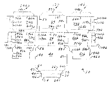
Fig. 1 is a top plan view of a blank for the container.
Fig. 2 is an isometric view of the blank
IATgs. 3-5 are isonietr3c views showing the l'orn5ation oTthe container.
Fig. 6 is an isometric view of the container.
DETAILED DESCRIPTION
Throughout the application the term attachment line is used. An attachment
line can
be a score line, a reverse score line, a slit and score line or a perforation
line depending on the
use of the line and its direction of rotation,
The blank 10 is formed of a central section 12 attached to two side sections
14a and
14b by rear outer corner panels l6a and 16b. The sections 12 and 14 are
otherwise separated.
The central section 12 is divided by parallel longitudinal attachment lines
18, 20, 22,
24, 26, 28 and 30 into a back attachment panel 32, an interior back panel 34,
an upper back
panel 36, an outer back panel 38, an outer bottom panel 40, an outer front
panel 42, an upper
front panel 44 and an inner front panel 46.
The outer bottom panel 40 is octagonal is shape and is wider between its side
edges
48 and 50 than the interior back panel 34, the rear upper panel 36 and the
outer back panel 38
are between their side edges 52 and 54. The outer bottom panel 40 has back
corner edges 56
and 58 extending between its back edge, defined by attachment line 24, and its
side edges 48
and 50, respectively. The outer bottom panel 40 also has front corner edges 60
and 62
extending between its front edge, defined by attachment line 26, and its side
edges 48 and 50,
respectively.
The inner front panel 48 has locking tabs 64 on its outer edge.
Each of the side sections 14 are the same and like reference numerals will be
used.
Each of the side sections is divided by parallel longitudinal attachment lines
66, 68, 70 and 72
into a side attachment panel 74, an inner side panel 76, an tipper side panel
78, an outer side
panel 80 and an inner bottom panel 82.
-1-

CA 02729214 2010-12-23
WO 2009/158243 PCT/US2009/047583
The inner bottom panel 82 has a front corner 84 that aligns with the
corresponding
front corner edge 60 or 62 of the outer bottom panel 40 in the formed
container. The front
edge 86 of the inner bottom panel 82 has locking indents 88 which align with
the locking tabs
64 of the inner front panel 48 in the formed container,
The rear outer corner panels 16 are connected to the side of outer back panel
38 along
transverse attachment lines 90 and are connected to the back side of each of
the outer side
panels 80 along transverse attachment lines 92. Attachment lines 90 and 92 are
parallel.
A front outer corner panel 94 is attached to the front side edge of outer side
panel 80
by transverse attachment line 96. An outer L-shaped front side panel 98 is
attached to the
front outer comer-pan-el 94-by -a 'transverse attachmenT line 100, Ali inner L
shaped ft rtt ide --
panel 102 is attached to the front side of the inner side panel 76 by
transverse attachment line
104.
The container is formed by folding the upper back panel 36 and its associated
inner
back panel 34 and back attachment panel 32inwardly around attachment line 22
and securing
back attachment panel 32 to outer bottom panel 40. The attachment line 18 will
be spaced
from attachment line 24 the same distance that attachment line 20 is spaced
from attachment
line 22. Also both upper side panels 78 and their associated inner side panels
76 and side
attachment panels 74 are folded inwardly around attachment lines 70 and side
attachment
panels 74 are secured to their respective outer side panels 80. The attachment
lines 66 will be
spaced from attachment lines 72 the same distance that attachment lines 68 are
spaced from
attachment lines 70. The securement of the attachment panels can be by glue or
staple. This
step can be at the container plant.
The outer bottom panel is bent upwardly around attachment line 24 and the
inner
bottom panels 82 are bent upwardly around attachment lines 72. The attachment
lines 72 are
offset slightly from attachment line 24 to allow the inner bottom panels 82 to
slide in over the
outer bottom panel 40 when the container is set up.
The movement of the outer bottom panel 40 and 72 causes the inner, top and
outer
back walls 34, 36 and 38 to rotate around their attachment lines 18, 20 and 22
to form the
back wall with the inner back panel spaced from the outer back panel. The
movement of the
inner bottom panels 82 causes the inner, top and outer side walls to rotate
around their
attachment lines 66, 68 and 70 to form the side walls with the inner side
panels spaced from
the outer side panels.
The back corner panels 16 are bent inwardly around attachment lines 90 until
the
corner panels align with the back corner edges 56 and 58 of the outer bottom
panel 40. The
-2-

CA 02729214 2010-12-23
WO 2009/158243 PCT/US2009/047583
outer side panels 80 are bent inwardly around attachment lines 92 until the
attachment lines
72 are aligned with the side edges 48 and 50 of the outer bottom panel 40. The
inner bottom
panels 82 slide over the outer bottom panel 40. The rear edges 106 of the
inner bottom
panels 82 are contoured to fit around the back attachment panel 32.
The front corner panels 94 are bent inwardly around attachment lines 96 until
the
corner panels align with the front corner edges 60 and 62 of the outer bottom
panel 40. The
inner L-shaped front side panels 102 are bent inwardly around attachment lines
104 and the
outer L-shaped front side panels 98 are bent inwardly around attachment lines
100 until the
panels are aligned with front edge 26 of the outer bottom panel and the panels
are contiguous.
The outer front panel 42 is"bent upwardly around attactrriient Brie 26,-the up
m frtmr,
panel 44 is bent around attachment line28 over the lower sections 108 and 110
of the L-
shaped panels 98 and 102 respectively, and the inner front panel 46 is bent
downwardly
around attachment line 30. The tabs 64 are fitted into the locking indents 88
to lock the
container walls in place.
The outer dimensions of the outer back panel, back comer panels, outer side
panels
and front corner panels correspond respectively to the outer bottom panel 40
back edge, back
corner edges 56 and 58, side edges 48 and 50 and front corner edges 60 and 62.
The back
edge of outer bottom panel 40 is attachment line 24 and the front edge of
outer bottom panel
40 is attachment line 26.
The container has outer corner panels which makes it easy to slide the
container into
place between other containers on shelves and provides enhanced graphic
appeal. The inner
side walls 80and inner back wall 34 meet to form an inner space that is
rectangular in cross
section allowing easier access to the product within the container. The upper
side panels and
upper back panel are aligned at the same height and provide a platform for
stacking the
containers. The spacing of the inner side walls from the outer side walls, and
the inner back
walls from the outer back walls allows the outer dimensions of the container
to be constant
from container to container for proper pallet sizing and shelf sizing while
allowing the
interior size of the container to be varied for different products. This is
done by changing the
dimensions of the top panels,
The container can be made from corrugated containerboard, containerboard,
fiberboard or paperboard.
It will be appreciated that other modifications may be made to the container
without
departing from the spirit of the invention.
-3-

Representative Drawing
A single figure which represents the drawing illustrating the invention.
Administrative Status

2024-08-01:As part of the Next Generation Patents (NGP) transition, the Canadian Patents Database (CPD) now contains a more detailed Event History, which replicates the Event Log of our new back-office solution.

Please note that "Inactive:" events refers to events no longer in use in our new back-office solution.

For a clearer understanding of the status of the application/patent presented on this page, the site Disclaimer , as well as the definitions for Patent , Event History , Maintenance Fee  and Payment History  should be consulted.

Event History

Description Date
Common Representative Appointed 2019-10-30
Change of Address or Method of Correspondence Request Received 2018-01-10
Grant by Issuance 2012-03-20
Inactive: Cover page published 2012-03-19
Inactive: Final fee received 2012-01-09
Pre-grant 2012-01-09
Notice of Allowance is Issued 2011-09-15
Letter Sent 2011-09-15
Notice of Allowance is Issued 2011-09-15
Inactive: Approved for allowance (AFA) 2011-09-13
Letter Sent 2011-08-30
All Requirements for Examination Determined Compliant 2011-08-16
Advanced Examination Requested - PPH 2011-08-16
Advanced Examination Determined Compliant - PPH 2011-08-16
Request for Examination Received 2011-08-16
Request for Examination Requirements Determined Compliant 2011-08-16
Inactive: Cover page published 2011-03-01
Letter Sent 2011-02-11
Inactive: Notice - National entry - No RFE 2011-02-11
Inactive: IPC assigned 2011-02-11
Application Received - PCT 2011-02-11
Inactive: First IPC assigned 2011-02-11
National Entry Requirements Determined Compliant 2010-12-23
Application Published (Open to Public Inspection) 2009-12-30

Abandonment History

There is no abandonment history.

Maintenance Fee

The last payment was received on 2011-06-08

Note : If the full payment has not been received on or before the date indicated, a further fee may be required which may be one of the following

  • the reinstatement fee;
  • the late payment fee; or
  • additional fee to reverse deemed expiry.

Please refer to the CIPO Patent Fees web page to see all current fee amounts.

Owners on Record

Note: Records showing the ownership history in alphabetical order.

Current Owners on Record
INTERNATIONAL PAPER COMPANY
Past Owners on Record
WALTER D., JR. KEEFE
Past Owners that do not appear in the "Owners on Record" listing will appear in other documentation within the application.
Documents

To view selected files, please enter reCAPTCHA code :


To view images, click a link in the Document Description column. To download the documents, select one or more checkboxes in the first column and then click the "Download Selected in PDF format (Zip Archive)" or the "Download Selected as Single PDF" button.

List of published and non-published patent-specific documents on the CPD .

If you have any difficulty accessing content, you can call the Client Service Centre at 1-866-997-1936 or send them an e-mail at CIPO Client Service Centre.


Document
Description 
Date
(yyyy-mm-dd) 
Number of pages   Size of Image (KB) 
Cover Page 2012-02-28 2 48
Representative drawing 2010-12-23 1 17
Drawings 2010-12-23 3 72
Description 2010-12-23 3 143
Abstract 2010-12-23 2 74
Claims 2010-12-23 2 81
Cover Page 2011-03-01 1 42
Representative drawing 2012-02-28 1 14
Maintenance fee payment 2024-05-21 52 2,158
Reminder of maintenance fee due 2011-02-21 1 112
Notice of National Entry 2011-02-11 1 193
Courtesy - Certificate of registration (related document(s)) 2011-02-11 1 103
Acknowledgement of Request for Examination 2011-08-30 1 177
Commissioner's Notice - Application Found Allowable 2011-09-15 1 163
PCT 2010-12-23 9 332
Correspondence 2011-08-16 6 324
Correspondence 2012-01-09 2 49