Note: Descriptions are shown in the official language in which they were submitted.
CA 02729249 2010-12-23
Device, method and control program for ophthalmologic,
particularly refractive, laser surgery
The invention relates to an apparatus for ophthalmological, in particular,
refrac-
tive laser surgery. It relates, further, to a control program for such an
appara-
tus, and to a method for generating such a control program.
Here, refractive laser surgery is to be understood as the alteration of the
imag-
ing properties of the optical system "eye" by means of laser radiation. The in-
teraction of the incident laser radiation with the eye alters the refractive
properties of one or more components of the eye. Since the imaging properties
of the eye are determined primarily by the cornea, in many cases refractive
laser
eye surgery involves treatment of the cornea. In such treatment, specific
appli-
cation of incisions and/or specific removal of material effect(s) alteration
of the
shape of the cornea; the term reshaping is therefore also used.
A prominent example of reshaping of the cornea for the purpose of altering its
refractive properties is that of LASIK (laser in-situ keratomileusis). In the
case
of LASIK, a small, superficial wafer, commonly termed a flap in the specialist
field, is first cut out of the cornea. The flap remains attached, at a portion
of its
edge, to the adjoining corneal tissue, such that it easily be folded to the
side and
subsequently folded back again. In practice hitherto, two methods, in particu-
lar, are used for producing the flap, being, on the one hand, a mechanical
method, by means of a microkeratome, and, on the other hand, a laser-technics
method, wherein, by means of femtosecond laser radiation (i.e. pulsed laser
radiation with a pulse duration in the fs range), a flat, sub-surface incision
is
made in the cornea, which incision is brought outwards, apart from the region
of
the hinged joint to the surface of the cornea. After the produced flap has
been
folded away, removal of material (ablation) from the thus exposed stroma is
effected, in accordance with a predefined ablation profile. The ablation
profile
specifies how much tissue is to be removed at which location of the cornea.
The
ablation profile is so calculated that, following the ablation, the cornea has
an
optimum shape for the treated eye and the previously existing optical imaging
defects of the eye are, as far as possible, corrected. Appropriate methods
have
long been available to the specialist field for calculation of the ablation
profile.
For example, an excimer laser, having a radiation wavelength in the UV range,
at approximately 193 nm, is used for the ablation.
CA 02729249 2010-12-23
-2-
Once the ablation profile has been determined for the eye that is to be
treated,
it is then calculated how the required removal can best be achieved with the
available laser radiation. The laser radiation used is normally pulsed
radiation.
It is therefore a matter of calculating, according to space and time, a
sequence
of laser pulses that, in interaction with the cornea, in particular the
stroma, ef-
fect the required reshaping of the cornea.
Beam guidance means, for so guiding a laser beam over the eye to be treated
that the required sequence of laser pulses in space and time is achieved, are
known per se in the prior art. In particular, the beam guidance means can com-
prise a deflection unit, also known as a scanner, which serves to deflect the
laser
beam in the transverse direction (x-y direction), as well as focussing optics,
for
focussing the laser beam at a required height position (z direction). The
deflec-
tion unit can comprise, for example, one or more galvanometrically controlled
deflection mirrors.
The present invention is not restricted to LASIK technics. it can also be
applied
in the case of other laser surgical operations on the eye, for instance in the
case
of PRK (photo refractive keratectomy), LASEK, EPI-LASIK, or in the case of
inci-
sional procedures, in which only incisions are made in the cornea. Moreover,
the
invention is also not restricted to treatment of the cornea by laser surgery;
ap-
plication of the invention for treatments of the lens, for example, are also
con-
ceivable.
The mentioned beam guidance means are controlled by means of a program-
controlled computer, in accordance with the ablation profile - or, more
generally,
in accordance with a treatment profile. If the treatment is a non-ablative
surgi-
cal treatment, the treatment profile can also, for example, be an incision
profile
that specifies at which location, and how deeply, an incision is to be made.
The treatment profile requires a reference point, to which the sequence of the
laser points is spatially related. It has been proposed, particularly in
connection
with LASIK ablation, that the mid-point of the pupil be used as a reference
point
for the ablation profile. The pupil is the opening that is left open by the
iris
diaphragm, and through which radiation passes into the eye and onto the
retina;
it has a relatively sharp contour, and therefore it is suitable for being
photo-
CA 02729249 2010-12-23
-3-
graphed by means of a camera and evaluated by means of image processing
programs. Appropriate camera technology and processing programs are avail-
able in the prior art.
The human eye, however, is not a stationary object, but one that executes
movements continually. There are various types of eye movements, some of
which are executed on differing timescales. Of importance only is the determi-
nation that the eye is never still. This applies even when it is attempted to
fix
the view upon a particular specified object; even then, unavoidable fixation
movements occur. Since the pupil participates in the mentioned eye movements
to a greater or lesser extent, the eye can be tracked, in respect of its move-
ments, through observation or monitoring of the pupil by camera. Correspond-
ing eye tracking devices (eye trackers) track movements of the eye by taking
sequences of images of the pupil, including the surrounding iris, and
subsequent
evaluation of the image sequences by means of software. In the context of
image evaluation, it is the instantaneous location of the pupil centre, in
particu-
lar, that is determined. Since the ablation centre (centre of the ablation
profile)
is always re-aligned on the thus determined pupil centre, the required spatial
sequence of laser pulses can be reliably directed onto the correct locations
of the
eye region to be treated.
The use of the pupil centre as a reference point for the ablation profile is
associ-
ated with a systematic disadvantage, however, since it does not take account
of
the depth of the anterior chamber of the eye, located in front of the pupil,
and
also does not take account of the thickness of the cornea. Eye movements are
generally rotational movements, the point of rotation being located within the
vitreous body. If the eye moves by a certain angle, the pupil centre is
displaced,
in the pupil plane, by a first value, while a point located on the surface of
the
cornea is displaced, in the corneal plane, by a second value, which is greater
than the first value, owing to the greater distance of the corneal point from
the
point of rotation in comparison with the distance between the pupil centre and
the point of rotation. In the presence of eye movements, therefore, alignment
of the ablation profile on the pupil centre results in inaccuracies.
Consideration may therefore be given to using, instead of the pupil centre, as
a
reference point for the ablation profile, a patent-specific point on the
cornea that
CA 02729249 2010-12-23
-4-
has a fixed spatial relationship to the pupil centre. In particular, in this
case
consideration may be given to the point at which the pupil axis pierces
through
the surface of the cornea. The pupil axis extends through the pupil centre and
through the surface of the cornea. In the case of corneal treatments, use of a
point located on the cornea as a reference point for the treatment profile
makes
it possible to avoid the mentioned systematic error that is encountered if, in-
stead, a point located at a distance from the cornea, such as, for instance,
the
pupil centre, is used as a reference point.
to For the purpose of calculating geometrically, from the pupil centre, a
processing
centre located on the cornea, there is a need for information concerning the
rotational radius of the eye and the radial distance between the two centres.
The latter is determined mainly through the depth of the anterior chamber of
the
eye; a small portion of this radial distance is further determined by the
thickness
of the cornea.
The invention proceeds from the knowledge that the depth of the anterior
chamber, including the thickness of the cornea, can vary to an extent from per-
son to person, that, to the end of improving the operation result, it is
advanta-
geous to ascertain metrologically in a definite manner, individually for the
respective patient, the depth of the patient's anterior chamber (including the
thickness of the cornea, if required), and to take this measured value into ac-
count in calculating the corneal processing centre from the position of the
pupil
centre. For example, in the case of a test group of patients, it could be
ascer-
tained that the depth of the anterior chamber, including the thickness of the
cornea, varied between approximately 2.8 and 4.5 mm within the test group. In
view of this ascertained breadth of variation, it is an aspect of the teaching
ac-
cording to the invention that it is possible that the assumption of a standard
value, for example 3.5 mm, for the depth of the anterior chamber, including
the
thickness of the cornea, might not be very appropriate to the actual
conditions in
the case of a current patient, and therefore there is a continuing need to
assume
a comparatively large error if the processing centre is calculated from the
pupil
centre with the use of such a standard value.
The object of the invention is to disclose for ophthalmological, in
particular,
refractive laser surgery, a method by which, for a specified treatment
profile, a
CA 02729249 2010-12-23
-5-
reference=point can be ascertained on the eye during treatment, which method
enables improved operation results to be achieved.
According to the invention, there is provided for this purpose an apparatus
for
ophthalmological, in particular, refractive laser surgery, comprising
- a laser-beam source,
- beam guidance means for location- and time-controlled guidance of the laser
beam, emitted by the laser-beam source, over an eye to be treated,
- a camera for taking an image of the iris and pupil of the eye,
- a program-controlled computer, connected to the camera, for controlling the
beam guidance means in accordance with a treatment profile, the computer
being set up to ascertain during the treatment of the eye, on the basis of the
image data supplied by the camera, the position of a specified point on the
cornea of the eye and to align the treatment profile relative to the thus as-
certained position of the corneal point.
According to the invention, the apparatus in this case is equipped with a
measur-
ing device for measuring a depth dimension of the eye to be treated, which
depth dimension is representative of the depth of the anterior chamber and, if
required, of the thickness of the cornea, the computer being supplied with the
measurement data of the measuring device, and being set up to ascertain the
position of the specified corneal point, taking account of the measured depth
dimension.
The invention thus teaches that the depth of the anterior chamber and, if re-
quired, the thickness of the cornea be measured individually for the
respective
patient, and the laser processing be aligned on a corneal point that has been
ascertained with these measured values having been taken into account. Pref-
erably, the reference point is located on the front side of the cornea. The
meas-
urement can be performed immediately prior to commencement of the surgery.
Coherent optical interferometric measurement methods for contactless meas-
urement of biological tissue, such as, for instance, optical coherence
tomography
(OCT), or coherence range reflectometry (OLCR: optical low coherence reflecto-
metry) have been available for some time. These measurement methods oper-
ate with broadband radiation (e.g., SLED, ASE, supercontinuum laser), and
allow
CA 02729249 2010-12-23
-6-
biological structures to be measured with high resolution, down to the range
of
1 pm and finer.
In a preferred development, the invention teaches that such a coherent optical
interferometric measuring device be integrated into the laser surgical
apparatus,
the measuring device being, in particular, an OLCR measuring device. The high
measuring accuracy of such a measuring device allows the variations of the
depth of the anterior chamber and of the thickness of the cornea between dif-
ferent patients to be resolved and recorded with precision. The integration of
the measuring device into the laser surgical apparatus is such that, in
particular,
the measuring beam emitted by the measuring device is directed onto the eye
coaxially with the laser beam used for treatment, such that the patient need
be
positioned only once and, if necessary, the measurement can be repeated during
the operation.
Not only the depth of the anterior chamber, but also the diameter of the eye
as
a whole, can differ from person to person. A differing eye diameter results in
a
correspondingly differing rotational radius in the case of rotational
movements of
the eye. Accordingly, in the case of a preferred embodiment, provision is made
whereby the computer is set up to ascertain the position of the specified
corneal
point, with a patient-specific, preoperatively ascertained rotational radius
of the
eye also being taken into account. Taking into account the individually meas-
ured rotational radius allows further improvements in comparison with the use
of
a rotational radius that is specified as a standard.
As already mentioned, the point at which the pupil axis pierces through the
surface of the cornea can be used as a specified corneal point. Alternatively,
a
corneal point that is in a fixed relative position in relation to this
piercing point
can be used.
In the case of LASIK interventions in particular, wherein the flap is first
folded
away, in order subsequently to perform the ablation, there is no possibility,
during the ablation, of directly sweeping the surface of the cornea after a
given
point. Accordingly, the reference point for the ablation centre can only be
calcu-
lated by indirect means. A possibility for this can consist in continuously
ascer-
taining, during the laser treatment, from the image data of the camera, a
CA 02729249 2010-12-23
-7-
current displacement dimension for the pupil centre that indicates the current
position of the pupil centre in relation to a given reference position. The
dis-
placement dimension of the pupil centre can be determined, in particular, in
the
form of a displacement vector, which represents the direction and extent of
the
displacement of the pupil centre in relation to the reference position. Eye
movements effected in the course of the laser intervention can then be ex-
pressed, respectively, by a displacement vector related to this reference
position
of the pupil centre.
Using the measured depth dimension, a displacement dimension, corresponding
to the displacement dimension of the pupil centre, can then be calculated for
the
specified corneal point, for example, again in the form of a displacement
vector.
The current position of the specified corneal point can be calculated from the
thus calculated displacement dimension of the specified corneal point and a
known reference position for this point. Expediently in this case, the
reference
position of the specified corneal point is that position assumed by the
specified
corneal point when the pupil centre is in its reference position. For example,
the
position at which the pupil axis pierces through the surface of the cornea,
and
the associated position of the pupil centre, can be ascertained once, at the
start
of the operation, and stored as reference positions for the specified corneal
point
and the pupil centre.
The invention further provides a control program for an apparatus for ophthal-
mological, in particular, refractive laser surgery, the apparatus comprising a
laser-beam source, beam guidance means for location- and time-controlled
guidance of the laser beam, emitted by the laser-beam source, over an eye to
be treated, a camera for taking an image of the iris and pupil of the eye, and
a
computer, which is connected to the camera and executes the control program,
for controlling the beam guidance means in accordance with a treatment
profile.
The control program is designed in such a way that the computer ascertains
during the treatment of the eye, on the basis of the image data supplied by
the
camera, the position of a specified point on the cornea of the eye and aligns
the
treatment profile relative to the thus ascertained position of the corneal
point.
The control program in this case ascertains the position of the specified
corneal
point taking account of a measured depth dimension of the eye to be treated,
CA 02729249 2010-12-23
-8-
which depth dimension is representative of the depth of the anterior chamber
and, if required, of the thickness of the cornea.
The control program can be stored, for example, on a machine-readable, port-
able data medium or in a memory chip that can be accessed by the computer.
Furthermore, the invention relates to a method for generating a control
program
for a program-controlled computer of an apparatus for ophthalmological, in
particular, refractive laser surgery, the apparatus being set up to route
laser
radiation onto or into the eye according to a spatial and time sequence that
is
determined by a required treatment profile and that is aligned relative to a
speci-
fied location of an eye to be treated. According to the invention, in the case
of
this method provision is made whereby a depth dimension of the eye to be
treated is measured at least once prior to the surgery, which depth dimension
is
representative of the depth of the anterior chamber and, if required, of the
thickness of the cornea, and the control program is so generated that, during
the surgery, it ascertains the specified value of the eye, taking account of
the
measured depth dimension.
The disclosures made and preferred exemplary embodiments explained previ-
ously in connection with the laser surgical apparatus according to the
invention
apply, correspondingly, to the control program and the method.
The invention is explained further in the following with reference to the ap-
pended drawings, wherein:
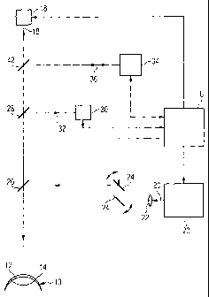
Figure 1 shows a schematic block representation of an exemplary embodiment
of an apparatus for refractive laser surgery of the eye,
Figure 2 shows a sectional representation of the front region of the eye, and
Figure 3 shows a sectional representation of the front region of the eye, in a
position of the eye rotated relative to Figure 2.
CA 02729249 2010-12-23
-9-
In Figure 1, an eye to be treated with refractive laser surgery is indicated
sche-
matically at reference 10. The cornea of the eye 10 and the edge of the pupil
are shown at 12 and 14, respectively.
The laser surgical apparatus according to Figure 1 shows, in a manner known
per se, a fixation light source (e.g. LED or laser) 18, which emits a (weak)
fixa-
tion beam 18' and at which the patient's view is directed for the purpose of
fixing the position of the eye.
The laser surgical apparatus further comprises a treatment laser 20, which
emits
treatment radiation 20' that is routed, via a lens 22, onto scanner mirrors
24, 24'
and directed, via a deflection mirror 26, onto the eye 10. For a LASIK
treatment,
the laser 20 can be, for example, an excimer laser, the radiation wavelength
of
which is 193 nm. It is understood that other treatment wavelengths may also
be used, if required, for other treatment purposes. A program-controlled com-
puter C controls the laser 20 and the scanner mirrors 24, 24' according to a
previously calculated treatment profile. It is assumed in the following that a
LASIK treatment is performed by means of the surgical apparatus represented;
accordingly, an ablation profile is assumed as a treatment profile.
The laser surgical apparatus additionally comprises a device for tracing eye
movements (eye tracker). The eye tracker comprises a camera 30, by means of
which images of the eye, specifically of the pupil and the iris, are taken,
via a
deflection mirror 28, in the direction of an arrow 32. The taken images are
then
evaluated in the computer C or in a preceding image processing unit, not repre-
sented, in order to track movements of the eye, which generally cannot be
avoided by the patient, despite the attempted fixing of the view onto the
fixation
light 18'. The computer C takes account of the detected eye movements in
controlling the scanner mirrors 24, 24', in order thus to keep the ablation
profile
aligned as constantly as possible in relation to a specified reference point
on the
surface of the cornea.
In addition, there is integrated into the laser surgical apparatus a measuring
device 34 for OLCR (optical low coherence reflectometry), which device, in a
manner known per se, includes a source for a measuring beam that is routed
onto the eye 10 via a deflection mirror 42. Via the deflection mirror 42, and
on
CA 02729249 2010-12-23
- 10-
the same path on which measuring radiation of the measuring device 34 is emit-
ted, the measuring device 34 receives radiation reflected from the eye 10.
This
is indicated by a double arrow 36.
At the start of the LASIK, still before the flap is cut free and folded away,
the
measuring device 34 measures the depth of the anterior chamber of the eye,
including the thickness of the cornea. Reference is now made to Figure 2 in
connection therewith. There, the anterior chamber of the eye is denoted by 44,
46 denoting the iris and 48 denoting the lens of the eye 10. The total
dimension
of the depth of the anterior chamber and the thickness of the cornea is
denoted
by d.
Further shown in Figure 2 is a pupil axis 50, which joins a pupil mid-point P
to a
piercing point D, at which the pupil axis 50 pierces through the front surface
of
the cornea 12.
A rotation of the eye results in a displacement of the pupil axis 50 and also,
accordingly, in a displacement of the pupil centre P and of the piercing point
D.
This situation is represented in Figure 3. There, the new pupil axis is
denoted
by 50'. For comparison, the pupil axis 50 of the state according to Figure 2
is
shown. a and b denote distances by which the pupil centre P and the piercing
point D, respectively, have been displaced relative to the state according to
Figure 2. It can be seen that, in the case of an eye movement, the piercing
point D is displaced to a significantly greater extent than the pupil centre
P, the
difference between the displacement dimensions a, b being dependent on the
depth of the anterior chamber 44 and the thickness of the cornea 12, i.e., in
total, on the depth dimension d.
The computer C of the laser surgical apparatus aligns the ablation profile,
not on
the pupil centre P, but on the piercing point D as the ablation centre. For
this
purpose, it ascertains, for example, the position of the pupil centre P and
the
position of the piercing point D once, prior to commencement of the operation,
and notes (stores) the thus ascertained values as reference positions. During
the laser treatment, the computer C continuously ascertains the respectively
current position of the pupil centre P on the basis of the image data of the
cam-
era 30, and calculates a displacement vector, which indicates the extent and
CA 02729249 2010-12-23
-11-
direction of the displacement of the pupil centre P between the stored
reference
position and the current state. From the thus ascertained displacement vector
for the pupil centre P, the computer C can calculate, on the basis of the meas-
ured depth dimension d and a rotational radius of the eye 10, which rotational
radius is likewise obtained metrologically or specified as a standard, a
displace-
ment vector for the piercing point D. This calculation is possible by means of
simple mathematics, for instance with the aid of the well-known intercept theo-
rems of geometry. From the thus obtained displacement vector for the piercing
point D and the stored reference position of this point, the computer C can
then
calculate the current position of the piercing point D. It is quite obvious
that the
amount of computation for these calculations is relatively small.