Note: Descriptions are shown in the official language in which they were submitted.
CA 02729480 2011-01-27
- 1 -
SELECTIVE CURE OF ADHESIVE IN MODULAR ASSEMBLIES
BACKGROUND OF THE INVENTION
[0001] The present invention relates generally to module construction for
assemblies
having several-to-many elements, and more specifically to systems and methods
for use of
selectively curable low viscosity/low surface tension adhesives for assembly
construction,
most particularly for battery module assembly construction.
[0002] It is common to produce module assemblies having elements secured
together
into an integrated monolithic structure. One method for securing the elements
together uses
an adhesive that bonds the elements to one or more fixtures. These fixtures
typically include
many openings that may be used to provide access to the elements, the inside
of the assembly,
or for other use. To inhibit adhesive from escaping from these openings during
manufacture,
conventional solutions use adhesives having great enough viscosity/surface
tension to inhibit
adhesive from exiting the apertures.
[0003] In many applications such an adhesive provides an acceptable solution.
In
other applications, an adhesive like this is problematic. One problem is that
the
viscosity/surface tension requires a fairly large hydrostatic head in order to
direct a suitable
quantity of adhesive into small margin bonding areas to adequately wet the
bonding surfaces
and provide sufficient bond strength. This hydrostatic head represents a large
quantity of
adhesive that is "wasted" in the sense that it does not contribute to the
security of the bonding
between the elements and the fixture.
[0004] It is not only the case that this adhesive is expensive and therefore
any wasted
adhesive adds to the ultimate cost. In some applications, like electric
vehicles, a further
drawback is that excessive adhesive adds "unnecessary" mass to the final
assembly while also
being unnecessarily expensive. As the number of elements in the assembly
increases, and as a
packing density of the elements increases, the costs in terms of expense and
mass become
quite significant because of the multiplicative accumulation of individual
excess across all the
CA 02729480 2011-01-27
- 2 -
elements in all of the modules. Any savings in reducing the quantity of
adhesive per
element/module is extremely effective in these cases as it reduces both
expense and mass.
100051 Adhesives have an associated curing profile that further influences the
use
and suitability of adhesives in module assemblies. There are two broad
categories of
adhesives ¨ one-part adhesives and two-part adhesives. Two-part adhesives are
adhesives that
include a base and a hardener. In contrast, a one-part adhesive includes the
functionality of
both the base and the hardener, but the activation or release of the hardener
depends upon
some externality for curing (e.g., temperature, ultraviolet radiation, water
vapor in the
environment, and the like). Epoxy is an example of a two-part adhesive having
a resin and a
hardener, with the hardener accelerating a polymerization (i.e., curing) of
the adhesive, the
specifics of the curing can be influenced by temperature and choice of
resin(s) and
hardener(s). Whether one-part or two-part, each adhesive has a curing modality
that produces
a rigid and strong bond in response to one or more curing agents. A cure time,
particularly a
minimum cure time to reach sufficient mechanical integrity for further
processing, is an
additional cost of use of adhesives. The cure time is sometimes related to the
total quantity of
adhesive used, using less adhesive can sometimes improve cure time cost.
100061 Further, in order for each battery module to remain mechanically robust
in
harsh environments such as within an automobile, a structural connection
(physical and
electrical) between each battery cell and module fixture should be stiff and
robust. Many
commodity cells do not include mechanical features that easily allow for such
connections.
For those that do, it is often difficult to make a stiff and robust mechanical
connection while
maintaining electrical connectivity requirements. Adhesives are able to
establish high shear
strength between smooth cell surfaces and fixtures of the module system while
also
maintaining any desired electrical isolation among the cells. However as noted
above,
adhesives can be expensive when used in this context and often lead to
addition of an
undesirable amount of mass to each battery module of a multiple-module battery
pack. There
is an additional cost to be considered, particularly as the number and density
of elements in a
module increases and still further as the number of these modules increases.
This additional
CA 02729480 2011-01-27
-3 -
cost relates directly to long cure times often required of adhesives, and
these long cure times
increase process cost.
[0007] As noted above, in a closely packed battery module, the quantity of
adhesive
applied depends in part on the hydrostatic head required to drive wetting of
the adhesive to the
required bonding surfaces. Some methodologies apply 1-2 mL of adhesive
(viscosity
approximately 7000 cps) to bond each 18650 battery cell into its own shallow
plastic
counterbore provided in a fixture. This quantity of adhesive is considered a
requirement to
achieve coverage of all bonding areas. However, the actual quantity of
adhesive required to
fill each bonding area alone is approximately 0.050-0.100 mL. Consequently,
when
considering what is needed for bonding the battery cell to the module fixture
alone, a large
amount of the adhesive is wasted.
[0008] The standard adhesives used in conventional solutions that are outside
the
bonding areas serves little purpose once the adhesive has sufficiently wetted
the bonding
surfaces, and this "excess" adhesive has virtually no purpose in the finished
product.
Reducing a dependency on the hydrostatic head to wet the bonding surfaces in
modularized
assemblies has a potential to produce significant cost savings by eliminating
the "wasted"
adhesive.
[0009] What is needed is a method and apparatus for decreasing costs (expense,
mass, and/or cure time) associated with use of adhesives when assembling
modularized
components.
BRIEF SUMMARY OF THE INVENTION
[0010] Disclosed are methods and systems for decreasing costs (expense, mass,
and/or cure time) associated with use of adhesives when assembling modularized
components,
particularly for assemblies having many elements such as for example battery
modules used in
electric vehicles. The methods and systems enable use of high-wettability
adhesives (defined
generally in this application as low viscosity and/or low surface tension
adhesives) for
assembling such modularized components. A first method including (a)
dispensing a high-
CA 02729480 2011-01-27
- 4 -
wettability adhesive into a first module fixture populated with a plurality of
elements wherein
the first module fixture provides a plurality of bonding wells with each
bonding well
accepting a first portion of one or more of the elements with the module
fixture including one
more apertures communicated with one or more of the bonding wells, the
adhesive being
selectively curable upon application of a curing modality; (b) applying the
curing modality
selectively to a first portion of the dispensed adhesive in a seal zone, the
seal zone including
one or more regions surrounding the apertures wherein the dispensed adhesive
in the seal zone
is sufficiently cured to inhibit significant quantities of the adhesive from
emerging from the
apertures while the adhesive continues to be dispensed into the module fixture
wherein the
curing modality is not applied to a second portion of the adhesive outside of
the seal zone; and
(c) applying the curing modality to the second portion of the dispensed
adhesive.
[0011] A high-wettability adhesive, for purposes of the present application,
includes
one-part and two-part adhesives having one or more wettability parameters,
when considering
a particular adhesive and the material of the substrate, selected from the
group consisting of a
viscosity in a range of about 100 to about 1000 centipoise, a surface tension
with the substrate
of the bonding wells producing a contact angle with the adhesive less than
about ten degrees
in air, and combinations thereof.
[0012] Another bonding method includes (a) populating a module fixture with a
plurality of elements, the module fixture transparent to a curing modality;
(b) masking
selected areas of a first portion of the module fixture using a mask opaque to
the curing
modality producing an unmasked first portion of the module fixture and a
masked first portion
of the module fixture; and thereafter (c) dispensing a high-wettability
adhesive into the
populated module fixture, the adhesive being selectively curable upon
application of the
curing modality and wherein the first module fixture provides a plurality of
bonding wells
with each bonding well accepting a first portion of one or more of the
plurality of elements
with the module fixture including one more apertures communicated with one or
more of the
bonding wells, the adhesive being selectively curable upon application of a
curing modality;
(d) curing, during the dispensing step (c), a first portion of the dispensed
adhesive in the
unmasked first portion upon application of the curing modality to the first
portion of the
CA 02729480 2011-01-27
- 5 -
dispensed adhesive in the first portion without application of the curing
modality to a second
portion of the dispensed adhesive in the masked first portion; and thereafter
(e) removing the
mask; and thereafter (f) curing uncured dispensed adhesive in the module
fixture, including
the second portion of the dispensed adhesive, upon application of the curing
modality to the
module fixture.
100131 A system includes a module fixture supporting a plurality of elements,
the
module fixture defining a plurality of bonding wells with each bonding well
accepting a first
portion of one or more of the elements with the module fixture including one
or more
apertures communicated with one or more of the bonding wells with the bonding
wells having
a nominal depth; and a dispensing system, coupled to the module fixture, for
dispensing a
high-wettability adhesive into each the bonding well and surrounding each the
element
substantially filling the bonding well up to the nominal depth without
significant overfill, the
adhesive being selectively curable upon application of a curing modality; and
a curing
structure for selectively exposing the adhesive to the curing modality as the
adhesive emerges
from the apertures during dispensation of the adhesive.
10014] Assemblies, such as for example battery packs, composed of a large
number
of elements (e.g., cells) on the order of tens to hundreds to thousands or
more elements,
implementing preferred embodiments of the present invention preferably have a
method of
mechanical integration that is low cost in terms of expense, mass, and process
time. The use
of appropriate high-wettability adhesives permits a stiff, robust,
electrically insulating
mechanical connection to the battery module fixture. The high packing density
of cells within
a battery pack limits the room available for dispensing adhesive evenly
throughout a battery
module, however the high-wettability adhesive is better suited for even
distribution,
particularly when the module fixture is adapted with ramps, wicking channels,
and guiding
surfaces and the like to direct dispensing adhesive into all populated bonding
wells. Features
in the module fixture that allow electrical interconnects on both ends of each
cell may provide
potential leak pathways for the adhesive during dispensation. Curing
modalities are applied to
adhesive exiting from the apertures to seal the module fixture and allow the
adhesive to
continue to fill the bonding wells and wet the bonding surfaces around the
elements
CA 02729480 2011-01-27
- 6 -
populating the bonding wells. The high wettability adhesive efficiently fills
the bonding wells
around the elements to be bonded, permitting the bonding wells to be
substantially filled
without significant overfilling (that is, the bonding wells are filled
sufficiently to wet all the
bonding surfaces without excessive (significant non-structural use). Ports
between the
bonding wells, a use of ramped guiding surfaces, and other features of the
fixtures promotes
even distribution of the high-wettability adhesive. A curing modality is
applied to all of the
adhesive in the bonding wells after the bonding surfaces are properly wetted.
[0015] In some of the preferred embodiments, the curing modality includes
application of light (e.g., ultraviolet radiation) which means that at least
selected structures of
the module fixture that define the bonding wells where the adhesive is
dispensed (and where
curing and bonding occurs) is transparent, and may therefore be visually
inspected. A use of a
cure indicator associated with the adhesive, such as color or some other
visual cue, is
advantageously used in certain embodiments to provide a quick assessment of
the quality
and/or status of the curing process in the bonding wells.
[0016] The embodiments of the present invention includes designs and
methodologies that promote the use of a limited amount of high-wettability
adhesive by
selectively curing (e.g., UV-curing) the adhesive as it attempts to exit out
of the apertures. As
noted above, due to the high wettability, the application area may remain
limited without
disadvantage. The high-wettability adhesive means that a time until the
bonding wells are
filled and that wetting of all bonding surfaces has occurred is relatively
short (in relative terms
compared to conventional systems and absolute terms). In addition to the
savings in process
time, a total quantity of adhesive used is greatly reduced, removing mass and
expense from
the assembled module.
[0017] In some embodiments, after adhesive application and during wetting, the
elements populating the bonding wells may be suitably positioned/aligned by
use of a curing
modality-transparent fixture applied to portions of the elements outside of
the bonding wells
of the fixture. For assemblies having multiple fixtures, this
positioning/aligning fixture may
be one of the other fixtures of the final assembly. (For multiple fixture
assemblies, and
because the preferred embodiments use high-wettability adhesives that respond
strongly to
CA 02729480 2011-01-27
- 7 -
gravity, any particular fixture being processed (e.g., populated, filled, and
some amount of
curing) is often described as a bottom fixture. It has this orientation during
processing, even
in cases that the fixtures may be oriented differently during operation. This
is not to say that
other orientations and arrangements are excluded, for example some application
may be found
for dispensing adhesive in a centrifugal system in which a "bottom" fixture
would be one
having a greater angular velocity than any other fixtures, with the high
wettability adhesive
dispensed from closer to a center of rotation of the system and flowing
outward into the
bonding wells and potentially leaking from the apertures, with the selective
curing occurring
on the periphery of the system.)
[0018] Curing modality (e.g., UV radiation) is applied to the adhesive by
directing
the UV radiation to the top side of the positioning/aligning assembly, curing
the adhesive in
the bonding areas of the bottom fixture. In embodiments having some areas
shadowed by
internal structures that limit exposure of some portions of the adhesive to
the curing modality,
the adhesive may include a multi-stage curing process. A first stage designed
to cure the
adhesive in seconds in response to one curing modality (e.g., UV radiation)
and a second stage
to cure the adhesive over a longer period in response to another curing
modality (e.g., days at
room temperature). This creates a two stage curing process for two sets of
mechanical
requirements, one for completing the remaining manufacturing steps and the
other for
durability in the field. While the adhesive joints are strengthened
sufficiently by the UV
radiation to continue on the manufacturing line, full strength as required for
field durability
may not be developed for days or weeks. When the module fixture itself is UV
transparent,
the entire cure operation can occur within seconds.
[0019] There may be many different implementations of embodiments of the
present
invention including permutations of one-part and two-part adhesives with
single-stage or
multi-stage curing or sealing formulations, with the staging being during
dispensing and/or
curing. For example, one embodiment includes use of a two-part high-
wettability adhesive
that "gels" or "skins" upon application of a sealing modality while curing in
a more
conventional manner. The gelling creates a barrier and seals the apertures
preventing leaks
and permitting the adhesive to fill the bonding wells and wet the bonding
surfaces. In other
CA 02729480 2011-01-27
- 8 -
applications, it is possible to vary the adhesive properties during dispensing
such that a first
phase adhesive is particularly formulated to enhance the sealing properties by
interaction with
a curing/sealing modality while a second phase of adhesive being dispensed is
particularly
formulated to bond the fixture to the elements.
BRIEF DESCRIPTION OF THE DRAWINGS
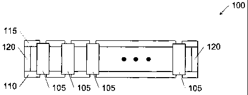
[0020] FIG. 1 is a block diagram of a system;
[0021] FIG. 2 is a detailed view of a battery cell in a module fixture;
[0022] FIG. 3 is a flowchart of a first preferred process;
[0023] FIG. 4 is a flowchart of a second preferred process; and
[0024] FIG. 5 is a detail of a side view of a representative bonding area
between a
battery cell and a module fixture.
DETAILED DESCRIPTION OF THE INVENTION
[0025] Embodiments of the present invention provide methods and systems for
decreasing costs (expense, mass, and/or cure time) associated with use of
adhesives when
assembling modularized components by enabling use of high-wettability
adhesives. The
following description is presented to enable one of ordinary skill in the art
to make and use the
invention and is provided in the context of a patent application and its
requirements. In the
following text, the terms "battery", "cell", "battery cell" and "battery cell
pack" may be used
interchangeably and may refer to any of a variety of different rechargeable
cell chemistries
and configurations including, but not limited to, lithium ion (e.g., lithium
iron phosphate,
lithium cobalt oxide, other lithium metal oxides, etc.), lithium ion polymer,
nickel metal
hydride, nickel cadmium, nickel hydrogen, nickel zinc, silver zinc, or other
battery
type/configuration. Further, the term "high-wettability," when considering a
particular
adhesive and material of the substrate, an adhesive having a characteristic
selected from the
group consisting of a viscosity in a range of about 0 (more preferably 100) to
about 1000
centipoise, a surface tension with the substrate producing a contact angle
with the adhesive
CA 02729480 2011-01-27
- 9 -
less than about ten degrees in air, and combinations thereof. Various
modifications to the
preferred embodiment and the generic principles and features described herein
will be readily
apparent to those skilled in the art. Thus, the present invention is not
intended to be limited to
the embodiment shown but is to be accorded the widest scope consistent with
the principles
and features described herein.
[0026] Adhesives have been formulated to selectively cure in response to some
curing modality, such as ultraviolet (UV) radiation. Selective curing permits
control of timing
and location of curing. Formulations also exist that permit for use of a
secondary curing
modality, such as time or temperature. This, combined with high-wettability
adhesives
formulated to have a low viscosity and/or low surface tension, with suitable
design of a
module fixture, provide a method and apparatus for enabling use of such
adhesives for
assembling modularized components, such as battery modules that provide lower
cost, lower
mass, and requires a shorter adhesive working time than conventional systems.
[0027] FIG. 1 is a block diagram of a system 100 including a plurality of
bonded
elements 105 supported by a bonding module fixture including a first module
fixture element
110, a second module fixture element 115, and an optional supporting element
120
interconnecting element 110 and element 115 in cases where additional
structural support is
not otherwise provided. System 100 is lower cost (e.g., lower expense, lower
mass, and/or
production time) as compared to conventional systems. While the present
invention may be
adapted for bonding many different types of elements 105, the invention will
be described
with reference to formation of a battery cell module made up of a large number
(e.g., hundreds
to thousands) of battery cells as element 105. Depending upon the
implementation and the
type of element, one or more module fixtures 110 are used to locate, bond, and
secure
elements 105. For the present example, two module support structures are
described, it being
understood that fewer or more module support structures may be used. Also in
the following
description, high-wettability adhesives are used. Gravity is effectively used
to move uncured
and dispensed adhesive, so there is reason to have references of lower and
upper when
describing the embodiments of the present invention. Such a reference does not
necessarily
CA 02729480 2011-01-27
- 10 -
relate to the orientation of intermediate or final products, but only to an
orientation during
dispensing, wetting, and at least some curing of the adhesives.
[0028] There are at least two general operational methods described herein,
see for
example, the discussion below regarding FIG. 3 and FIG. 4. FIG. 3 generally
describes a two-
part adhesive method and FIG. 4 generally describes a one-part adhesive. Some
of the
descriptions in one method are applicable to the other.
[0029] The adhesives described herein for use are selectively curable low
viscosity
and/or low surface tension adhesives. For purposes of the present invention,
low viscosity
means an adhesive in a range of about 0-2000 centipoise, preferably about 50-
1000
centipoise, and most preferably a range of about 100-500 centipoise. For
purposes of the
present invention, low surface tension means an adhesive, when measuring a
contact angle
between the adhesive relative to a material of a substrate (e.g., the bonding
surface in the
bonding well) in air, the contact angle is less than about 30 degrees,
preferably less than about
degrees, and most preferably less than about 5 degrees.
[0030] The adhesives are also selectively curable upon application of a curing
modality. The curing modality used in the preferred embodiments includes UV
curing, but
other curing modalities may be used, with some adjustment of the systems and
methods
described herein. These alternate curing modalities may include, for example,
application
of/exposure to an electron beam, peroxide, cationics, amines, hydroxyl groups,
thermal
radiation, and combinations thereof. In the context of the present invention,
unless otherwise
contradicted by the context, selective cure also includes selective "gelling"
such that an
adhesive may not cure as that term is generally understood, but it may
harden/gel sufficiently
to seal apertures and inhibit exit or flow of adhesive.
[0031] Suitable two-part adhesives include those adhesives having a resin with
a
hardener such that it cures over time such as an epoxy-amine adhesive system
or other
secondary curing modality (e.g., thermal energy). Other suitable adhesives
will be one-part
adhesives that cure in response to exposure/application of a single primary
curing modality.
CA 02729480 2011-01-27
- 11 -
[0032] Other terms used in the present describe module fixtures that have
curing
modality transparency (which refers to a property of the module fixture that
it does not block
or significantly impair exposure/application of the curing modality to the
relevant adhesive.
In some cases, optional channels or "spigots" are provided in the module
fixture to permit or
promote passage and distribution of the curing modality throughout the
structure or to
selective other regions or portions of the structure. The present application
also uses the term
"curing enclosure" as a reference to an immersive source of the curing
modality to
expose/apply the curing modality to large areas of the adhesive. For example,
a UV oven is
an example of a curing enclosure for a UV curing modality.
[0033] FIG. 2 is a detailed view of a portion 200 of a module fixture 205
supporting
a battery cell 210 (not to scale). Module fixture 205 defines a bonding well
215 that receives
cell 210, a space between a wall of well 215 and cell 210 being filled with
high-wettability
adhesive, preferably up to a nominal fill depth 217 without significant
overfilling. For
purposes of this application, overfilling relates to dispensation of a
quantity adhesive in excess
of structural purposes. A total amount of dispensed adhesive in a
manufacturing environment
is subject to normal variations. A goal of the present invention is to reduce
a total amount of
adhesive by permitting elimination\reduction of overfill. The embodiments of
the present
invention provide solutions to reducing any overfilling of the bonding wells,
but some overfill
will be acceptable or desirable in some implementations. A marginal utility of
extra adhesive,
in a structural sense, begins to decline at the point overfilling begins. This
is a preferred
reference for beginning a determination as to whether a bonding well has been
overfilled.
[0034] The relative dimensions between walls of fixture 205 and cell 210 are
exaggerated in FIG. 2 and the space is actually much smaller. It is possible
to limit the
quantity of adhesive in this fashion because of the high-wettability adhesives
used in the
present invention combined with the selective curing herein described. The
detail of FIG. 2 is
repeated laterally for each cell 210 to form an entire matrix of battery cells
closely packed
together.
[0035] Dispensed adhesive in bonding well 215 surrounding cell 210 is
selectively
cured by exposure/application of a curing modality from a source, for example,
a UV source
CA 02729480 2011-01-27
- 12 -
220 (source 220 may be implemented in one or more locations, such as, for
example, as
shown with a lower UV lamp and an upper UV lamp). Source 220 may also be
implemented
as a single UV lamp in each location or include several structures, such as
for example, a
matrix of small sources, with one small source corresponding to each bonding
well 215
location. Structure 205 is formed with ramps 225 and channels 230 to aid in
flowing
dispensed adhesive into all bonding wells 215 to wet all bonding surfaces of
structure 205 and
cell 210.
[0036] Those regions of the module fixture, particularly around the apertures
and
bottoms of the bonding wells define a seal zone. The exposure of selectively
curable adhesive
as it enters the seal zone to form a barrier against further adhesive exit is
one of the features of
the present invention that enables use of high-wettability adhesive. In some
implementations,
the seal zone is spatially-crafted to form a particular three-dimensional
region. For example,
when the curing modality includes application of ultraviolet radiation, one or
more beams of
UV light may be focused, dispersed, or otherwise crafted for desired effect.
In a case of using
UV LEDs for producing the curing modality into the seal zone, some
implementations
advantageously produce a conical beam for parts of the seal zone near fixture
apertures.
Shaping portions of the seal zone in this way can offer other advantages for
later processing of
the module.
[0037] The dispensed adhesive, being a high-wettability adhesive, will begin
to
"leak" from areas in a wall of module fixture 205, such as a connection port
235 in bonding
well 215 underneath cell 210, such as may be used for an electrical
interconnect. As the
adhesive begins to emerge, it is cured almost instantly, thereby sealing the
aperture against
further loss of adhesive and permitting the dispensed adhesive to fill bonding
well 215, while
also maintaining an ability to make electrical/mechanical contact with cell
210.
[0038] Some embodiments include one or more masks 240 that block
exposure/application of the curing modality from selected areas of fixture
portion 200. Other
embodiments include curing modality channels 245 or spigots that direct and/or
promote
distribution/redistribution of the curing modality throughout selected regions
of the module
fixture. One or more of adhesive channels 230, masks 240, and light channels
245 are
CA 02729480 2011-01-27
- 13 -
optional elements used as necessary or desirable in implementing embodiments
of the present
invention.
[0039] FIG. 3 is a flowchart of a first preferred process 300. Process 300
preferably
uses a two-part adhesive having two-stage curing: a UV cure and a time cure.
Process 300
uses a UV-opaque module fixture. In general, process 300 includes populating
the battery
cells into a first module fixture 305. This is similar to a tray holding fifty
or more upright
battery cells seated within the bonding wells described above.
100401 The UV source is turned on (step 310). One preferred embodiment
provides
for two UV sources, a lower UV source that is "under" the UV-opaque module
support
structure and an upper UV source that is "over" the UV-opaque module support
structure.
Step 310 turns on the lower UV source, in this case, a UV lamp.
[0041] Step 315 of process 300 applies the high-wettability adhesive. Because
of its
properties, it begins to flow readily and begins to wet the bonding surfaces
in the bonding
wells. Process 300 includes an optional step 320 that installs a UV-clear
fixture onto tops of
the battery cells. The first module fixture supports/holds/bonds one end of
the battery cells.
The battery cells may not be sufficiently aligned vertically with vertical
axes of the bonding
wells. Additionally, until the adhesive cures sufficiently, there is some risk
of one or more of
the battery cells becoming misaligned. One of the advantages of the present
invention over
conventional systems is a relatively quick curing time, which permits post-
adhesive-
application assembly processing to continue sooner than when conventional
systems are
employed. Such processing may tend to disturb the preferred location/alignment
of the cells.
The fixture of step 320, when used, is designed to locate and hold a second
end of the cells
during adhesive application and/or post-adhesive-application processing while
the adhesive
suitably cures. In some cases, the second fixture improves the tolerance of
the assembly. This
fixture may be a temporary structure or may be a permanent structure, such as
the opposing
module fixture to be permanently affixed to the second end of the battery
cells.
[0042] In step 325, the applied adhesive wets the bonding areas and some
portion of
the applied adhesive emerges from the bottom of the structure, such as at
various apertures
CA 02729480 2011-01-27
- 14 -
communicated to the bonding wells, such as around connector vias and other
features and
ports. Emerging adhesive is immediately exposed to the curing modality (e.g.,
optical
communication with the UV radiation from the lower UV lamp) and cures within a
matter of a
few seconds to a few minutes, depending upon implementation details. The cured
adhesive
seals the apertures and inhibits additional exit of the adhesive, which in
turn permit the
adhesive to fill the bonding well and wet all of the desired bonding surfaces.
Because the
module fixture is UV-opaque, the lower UV lamp is not generally in optical
communication
with adhesive within the bonding well. The module fixture is designed to
direct the majority
of the applied adhesive to the bonding surfaces between the battery cells and
module fixture
through the use of ramps and/or channels and other structures.
[0043] Step 330 turns off the lower UV source and turns on the upper UV
source.
The upper UV source applies the curing modality to the top of the dispensed
adhesive to cure
it as well. The UV-opaque module fixture inhibited the curing modality from
the lower UV
source to cure the adhesive within the bonding well, thereby permitting it to
flow and wet all
desired bonding surfaces. The upper UV lamp cures the adhesive in the bonding
well from
the "top" side of the UV opaque module fixture. The curing modality from the
upper lamp is
applied through the UV-clear fixture should it have been installed.
[0044] Step 335 cures the adhesive exposed by the upper UV source in a matter
of a
few seconds to minutes. Thereafter, further mechanical processing of the
module may begin.
Any shadowed adhesive (e.g., any adhesive not exposed to the curing modality)
will cure over
the next days or weeks. As described above, the UV radiation was the primary
curing
modality. The two-part adhesive preferably used in the process 300 includes a
secondary
curing modality ¨ time (e.g., responsive to a hardener used in the adhesive)
or application of
thermal radiation. (The post-exposed module may be heated in the latter case
to finish the
curing of shadowed adhesive. In some implementations it is sufficient to let
the adhesive sit
and cure over time.)
[0045] Battery cells sometimes include a shrink wrap cover. Populating the
fixtures
with battery cells lacking such shrink wrap has an advantage in some
embodiments. For
example, battery cells lacking the shrink wrap exposes UV-reflective nickel-
plated steel cases
CA 02729480 2011-01-27
- 15 -
of a certain type of cells. The steel cases of these cells may be used, as
necessary or desired,
to facilitate UV penetration and redistribution of the curing modality
throughout the closely
packed cells to the bonding areas. In addition, a draft of the bonding well in
the mechanical
structure may be increased to allow better optical access to the full bonding
area. Once the
bonding surfaces are wetted by the adhesive, the fixtured module may be placed
in a UV oven
to cure the exposed adhesive in all the bonding areas throughout the assembly.
This UV cure
provides a first stage of mechanical strength to continue with subsequent
manufacturing
operations. Over the following days or weeks, adhesive that was shadowed
during the initial
UV exposure cures with time at room temperature.
[0046] Process 300 may also be used on the second side of the battery module,
with
the exception that the primary UV cure may be applied through ports in the
bottom piece of
module fixture. UV emitting "spigots" may extend through the ports and fully
cure some
sections while "skin curing" the majority of the adhesive such that the module
may be tipped
or flipped in further handling.
[0047] FIG. 4 is a flowchart of a second preferred process 400. Process 400,
similar
in many respects to process 300 described herein, preferably uses a UV-clear
module fixture
and a one-part UV curing adhesive. One-part adhesives are advantageous for
manufacturing
as compared to two-part adhesives because two-part adhesives require disposal
or cleaning of
equipment that comes into contact with the mixed two-part adhesive.
[0048] In process 400, the cells are populated into the UV-clear module
fixture (405)
and the structure is closed. All areas on the bottom of the module except
where adhesive may
exit from the bottom of the structure are masked by a UV-opaque plate or
barrier (410). A
UV source (e.g., a single lamp exposing all unmasked areas or many UV LEDs of
an LED-
matrix, one LED for each aperture) is turned on (415) and adhesive applied
(420) that wets the
bonding surfaces and begins to exit from the various apertures communicated to
the bonding
wells. During wetting, the bottom of the assembly is exposed to UV light from
the UV
source(s), curing adhesive as it attempts to exit from the apertures in the
bottom (425). After
wetting, the mask is removed (430), and the entire assembly is exposed to UV
light,
penetrating the structure and curing the adhesive (435) throughout. At this
point, when
CA 02729480 2011-01-27
- 16 -
necessary or desirable, the assembly is opened for additional operations. Once
these are
complete, the assembly is once again closed, and the above process is repeated
for the other
side of the enclosure. The assembly is now UV cured on both sides.
[0049] FIG. 5 is a detail of a side view of a portion 500 of a cured module
fixture of
a representative bonding area 505 between a battery cell 510 and a module
fixture wall 515.
Portion 500 is a better representation of the scale of the boding surfaces
wetted and cured by
the present invention. The adhesive is shown in cross-hatched shading,
illustrating that the
preferred implementation limits escape of the adhesive out the bottom and
fills the bonding
wells without overfilling. In a manufacturing environment, it can be difficult
to dispense the
precise quantity of adhesive, sometimes the bonding well is not completely
filled or
sometimes it is overfilled. Underfilling is undesirable as it reduces a
strength of the bonding
while overfilling is undesirable because of the extra cost. A goal is to
achieve an amount of
adhesive generally represented by the elements shown in FIG. 5, with the
understanding that
more or less adhesive may be actually used.
[0050] A modification of the disclosed embodiments includes use of a two-phase
dispensing of adhesive. In a first phase, an adhesive formulated to be highly
wetting while
being quickly "skinned" is dispensed and then in a second phase a structural
adhesive is
dispensed. The first phase adhesive primary objective is to create a barrier
around the
apertures to seal the fixture and stop the second phase adhesive from exiting.
[0051] The system above has been described in the preferred embodiment of
multicell battery pack used in electric vehicle (EV) systems. In the
description herein,
numerous specific details are provided, such as examples of components and/or
methods, to
provide a thorough understanding of embodiments of the present invention. One
skilled in the
relevant art will recognize, however, that an embodiment of the invention can
be practiced
without one or more of the specific details, or with other apparatus, systems,
assemblies,
methods, components, materials, parts, and/or the like. In other instances,
well-known
structures, materials, or operations are not specifically shown or described
in detail to avoid
obscuring aspects of embodiments of the present invention.
CA 02729480 2011-01-27
- 17 -
[0052] Reference throughout this specification to "one embodiment", "an
embodiment", or "a specific embodiment" means that a particular feature,
structure, or
characteristic described in connection with the embodiment is included in at
least one
embodiment of the present invention and not necessarily in all embodiments.
Thus, respective
appearances of the phrases "in one embodiment", "in an embodiment", or "in a
specific
embodiment" in various places throughout this specification are not
necessarily referring to
the same embodiment. Furthermore, the particular features, structures, or
characteristics of
any specific embodiment of the present invention may be combined in any
suitable manner
with one or more other embodiments. It is to be understood that other
variations and
modifications of the embodiments of the present invention described and
illustrated herein are
possible in light of the teachings herein and are to be considered as part of
the spirit and scope
of the present invention.
[0053] It will also be appreciated that one or more of the elements depicted
in the
drawings/figures can also be implemented in a more separated or integrated
manner, or even
removed or rendered as inoperable in certain cases, as is useful in accordance
with a particular
application.
[0054] Additionally, any signal arrows in the drawings/Figures should be
considered
only as exemplary, and not limiting, unless otherwise specifically noted.
Furthermore, the
term "or" as used herein is generally intended to mean "and/or" unless
otherwise indicated.
Combinations of components or steps will also be considered as being noted,
where
terminology is foreseen as rendering the ability to separate or combine is
unclear.
[0055] As used in the description herein and throughout the claims that
follow, "a",
"an", and "the" includes plural references unless the context clearly dictates
otherwise. Also,
as used in the description herein and throughout the claims that follow, the
meaning of "in"
includes "in" and "on" unless the context clearly dictates otherwise.
[0056] The foregoing description of illustrated embodiments of the present
invention, including what is described in the Abstract, is not intended to be
exhaustive or to
limit the invention to the precise forms disclosed herein. While specific
embodiments of, and
CA 02729480 2012-11-19
- 18 -
examples for, the invention are described herein for illustrative purposes
only, various
equivalent modifications are possible, as those skilled in the relevant art
will recognize and
appreciate. As indicated, these modifications may be made to the present
invention in light of
the foregoing description of illustrated embodiments of the present invention.
100571 Thus, while the present invention has been described herein with
reference to
particular embodiments thereof, a latitude of modification, various changes
and substitutions
are intended in the foregoing disclosures, and it will be appreciated that in
some instances
some features of embodiments of the invention will be employed without a
corresponding use
of other features. Therefore, many modifications may be made to adapt a
particular situation
or material. The scope of the claims should not be limited by the preferred
embodiments set
forth in the examples, but should be given the broadest interpretation
consistent with the
description as a whole.