Note: Descriptions are shown in the official language in which they were submitted.
CA 02729588 2010-12-29
WO 2010/003083 PCT/US2009/049557
1
PACKAGING MACHINE AND METHOD OF PACKAGING ARTICLES
FIELD OF THE INVENTION
The present invention relates to a packaging machine and a method of packaging
articles. More particularly, but not exclusively, the invention relates to a
method of
manipulating articles in a stream of articles and an apparatus for carrying
out the
method and to a packaging machine having a layout which is capable of
processing
multiple carton types and formats.
BACKGROUND OF THE INVENTION
In the field of packaging it is often required to provide consumers with a
package
comprising multiple primary product containers, such multi-packs are desirable
for
shipping and distribution and for display of promotional information.
It is known to automate packaging of the primary product containers into the
package
by placing the primary product containers into a carton formed from a carton
blank.
It is also desirable to produce packaging machine which can be coupled to the
output of
a processing machine which places product into the primary product containers,
for
example this may be a bottling or canning machine. It may be further desirable
to
reorganise the output stream of primary product containers to facilitate
placement into
cartons.
A further objective of the present invention is to provide a packaging machine
having a
layout which is capable of processing a variety of different carton formats;
for example:
wrap around carton, basket carriers, fully enclosed cartons, and to be able to
side or end
load, top load or bottom load the chosen carton format with primary product
containers. Furthermore it is desirable to be able to rapidly change the
format or layout
of the packaging machine to adapt to the carton format or loading method
required.
CA 02729588 2010-12-29
WO 2010/003083 PCT/US2009/049557
2
It is also desirable to produce a packaging machine which can place the
packages
containing the primary product containers into a further package for shipping
and
distribution of the multi-packs.
It is also desirable to place the primary product containers in a loose format
into the
tertiary package such that the primary product containers can be distributed
individually
by a retailer to a consumer.
SUMMARY OF INVENTION
According to a first aspect of the present invention there is provided a
packaging
subsystem for application of a carton blank to one or more articles which
packaging
subsystem comprises a carton hopper for holding carton blanks, a feeder
mechanism for
removing carton blanks from the hopper and placing them on a first conveyor,
folding
mechanism for folding the panels of the carton blank about the first conveyor
and a
transfer mechanism for picking up, in a substantially inverted U shape, and
placing the
folded carton blank about one or more articles being transferred on a second
conveyor.
Preferably, either the first or second conveyor or both first and second
conveyors are
continuously moving.
Preferably, the second conveyor is parallel to said first conveyor.
According to a second aspect of the present invention there is provided a
packaging
subsystem for arranging an input stream of articles comprising at least one
lane or
column of articles, wherein the subsystem comprises an article pick and place
robot for
picking up one or more articles from stream of articles and placing them on a
conveyor,
the pick and place robot comprising an arm pivotally mounted above the
conveyor and a
gripper head pivotally coupled to the arm, an article retardation mechanism is
provided
for slowing articles upon the conveyor wherein a stream of articles is output
from the
CA 02729588 2010-12-29
WO 2010/003083 PCT/US2009/049557
3
subsystem which has been arranged such that it comprises at least one more
column
or lane of articles than the input stream of articles.
Preferably, the input stream of articles comprises two lanes and output stream
of
articles comprises four lanes of articles.
Preferably, the input stream of articles comprises two lanes and output stream
of article
comprises three lanes of articles.
Preferably, the retardation device comprises at least one lug coupled to an
endless
conveyor which lug is inserted into the stream of articles downstream of the
pick and
place robot.
According to a third aspect of the present invention there is provided a
packaging
machine comprising the subsystems hereinbefore described.
According to a fourth aspect of the present invention there is provided a
packaging
machine comprising an article conveyor for providing a stream of articles to
be
packaged, a first hopper for storing first carton blanks, a second carton
hopper for
storing second carton blanks, a first feeder mechanism for placing the first
carton blanks
on a first conveyor and a second feeder mechanism for placing the second
carton blanks
on a second conveyor and a third conveyor for receiving grouped articles from
the input
conveyor and at least one transfer device capable of moving articles from the
input
conveyor to either the first or third conveyor such that the articles may be
packaged in
the first or second blank respectively.
Preferably, the packaging machine further comprises a second transfer
mechanism
capable of transferring articles between the input conveyor and the first
conveyor or
carton blanks between said second conveyor and the third conveyor.
Preferably, the first or second transfer mechanisms comprise interchangeable
head
units allowing them to handle different carton types or articles and/or to
switch
between transferring articles and cartons.
CA 02729588 2010-12-29
WO 2010/003083 PCT/US2009/049557
4
According to a fifth aspect of the present invention there is provided a
packaging
machine comprising two or more packaging subsystems each capable of packaging
articles into a carton, wherein the packaging subsystems share a common source
of
articles to be packaged and at least one transfer mechanism is provided for
transferring
articles from the common source to any of the two or more packaging
subsystems.
Preferably, each of the two packaging subsystems packages articles into
different carton
types or formats.
Preferably, the cartons processed by one packaging subsystem of said two or
more
packaging subsystems are placed into the cartons processed by another
packaging
subsystem of said two or more packaging subsystems.
According to a sixth aspect of the present invention there is provided a
method of
continuously forming a package comprising:
providing a continuous stream of carton blanks upon a first conveyor,
providing a continuous stream of articles upon a second conveyor,
folding said carton blanks about the first conveyor into an inverted U-Shaped
structure,
sequentially picking up at least one of said inverted U-shaped structures and
placing it about one or more articles upon the second conveyor,
folding panels of the carton blank to complete construction of a carton about
the
group of articles to form a continuous stream of packages.
Preferably, said carton blanks are continuously moving during formation of the
package.
Preferably, said articles are continuously moving during formation of the
package.
According to a seventh aspect of the present invention there is provided a
method of
manipulating articles in a stream of articles comprising:
CA 02729588 2010-12-29
WO 2010/003083 PCT/US2009/049557
providing a continuous input stream of articles comprising at least one column
of
articles upon a conveyor comprising at least one more lane than columns of
articles,
picking up at least one article from at least one of said columns of articles,
5 placing said picked up at least one article into a vacant one of said at
least one
more lanes,
retarding articles in all of said at least one more lanes such that a
continuous
output stream of articles comprising at least one more column than the input
stream is created.
BRIEF DESCRIPTION OF THE DRAWINGS
Exemplary embodiments of the invention will now be described with reference to
the
accompanying drawings, in which:
FIGURE 1. is a perspective view from above of a packaging machine according to
a first
embodiment of the invention;
FIGURE 2. is a perspective view from above of subsystem at the input end of
the packaging
machine of FIGURE 1 at a first stage of a first mode of operation;
FIGURE 3. is a perspective view from above of subsystem FIGURE 2 at a second
stage of a first
mode of operation;
FIGURE 4. is a perspective view from above of a carton filling station of the
packaging machine
of FIGURE 1 in the first mode of operation;
FIGURE 5. is a perspective view from above of the subsystem at the input end
of the packaging
machine of FIGURE 1 at a first stage of a second mode of operation
FIGURE 6. is a perspective view from above of subsystem of FIGURE 5 at a
second stage of a
second mode of operation;
FIGURE 7. is a perspective view from above of subsystem of FIGURE 5 at a third
stage of a
CA 02729588 2010-12-29
WO 2010/003083 PCT/US2009/049557
6
second mode of operation;
FIGURE 8. is a perspective view from above of subsystem of FIGURE 5 at a
fourth stage of a
second mode of operation;
FIGURE 9. is a perspective view from above of a carton filling station of the
packaging machine
of FIGURE 1 in the second mode of operation;
FIGURE 10. is a perspective view from above of the carton filling stations of
FIGURE 4 and FIGURE
9 to a second embodiment of the invention in a first stage of operation;
FIGURE 11. is a perspective view from above of the carton filling stations of
FIGURE 4 and FIGURE
9 to a second embodiment of the invention in a second stage of operation.
DETAILED DESCRIPTION OF EXEMPLARY EMBODIMENTS OF THE PRESENT INVENTION
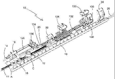
Referring to FIGURE 1 there is shown a perspective view of a packaging machine
10
capable of accepting an input of primary products, such as, but not limited
to, bottles or
cans, hereinafter referred to as articles.
Articles A are transferred in a stream to the input end of the packaging
machine 10 on
an input conveyor 11. Carton blanks B are stored in a hopper or magazine 14
and
transferred from the hopper 14 to a carton conveyor 19 via a pre-former 18 by
a carton
blank feeder mechanism 16. The carton blank feeder mechanism 16 picks up a
carton
blank B from the hopper 14, in a first embodiment three carton blanks B are
picked up
simultaneously, the carton blank B is pushed into the pre-former 18 by the
carton blank
feeder mechanism 16. The pre-former 18 forces the side panels and end panels
of the
carton blank B to be folded into a substantially perpendicular relationship to
one
another and to a base panel of the carton blank B, thus partially forming a
carton C from
the carton blank B. The partially formed carton C is capable of receiving
articles A prior
to completing assembly of the carton C.
The carton blank feeder mechanism 16 removes the partially assembled carton C
from
the pre-former 18 and places them on the carton conveyer 19. The carton
conveyor 19
is disposed alongside and substantially parallel to the input conveyor 11.
CA 02729588 2010-12-29
WO 2010/003083 PCT/US2009/049557
7
The stream of articles A may then be rearranged by an article manipulator 12,
to be
described in more detail below, before being transferred to a carton filling
station
where they are picked up by a carton filler device 22 and placed into the
partially
assembled carton C. The filled cartons C are then transferred to a closing
station where
a carton closer 24 folds the top panel of the carton C into position and folds
and secures
top end flaps to one of the side panels and the end panels of the carton C
respectively.
The fully assembled packages are then transferred from the packaging machine
10 for
further processing (not shown) by an output conveyor 26.
Turning in more detail to the article manipulator 12, FIGURE 2 and 3
illustrate operation
of the article manipulator 12 in a first mode of operation, in this mode of
operation the
article manipulator 12 converts the input stream of articles A from two lanes
of articles
A into four lanes of articles A.
The article manipulator 12 comprises an arm 48 pivotally mounted overhead of
the
input stream of articles A. The arm 48 is pivotally coupled to a gripper head
46 which in
this embodiment is capable of grasping twelve articles A, a drive means is
provided to
reciprocally rotate the arm above the input stream of articles A, a further
drive means is
provided to maintain the gripper head 46 in parallel orientation, when viewed
from
above, with the input conveyor 11, it envisaged that separate drive mechanisms
may be
provided for both functions or that a single drive mechanism may be used. It
is
anticipated that the drive mechanism may be provided by a servo motor or other
suitable electric motor; however in alternative embodiments a hydraulic or
pneumatic
mechanism may be used.
Changing the number of lanes or columns of articles A in the stream of
articles A is
achieved by picking up six articles A from each of the two input lanes and
placing them
in two additional lanes as shown in Figure 2 and 3. The article manipulator 12
allows the
subsequent six articles A in each of the two input lanes to pass by
unhindered. The
article manipulator 12 then picks up twelve further articles A following the
twelve
unhindered articles A and places them in the two additional lanes.
CA 02729588 2010-12-29
WO 2010/003083 PCT/US2009/049557
8
In order to provide a continuous stream of articles A comprising four lanes of
articles A
it is necessary to retard the articles A downstream of the article manipulator
12. This is
achieved by introducing retardation lugs 56 into the reorganised stream 20 of
articles A.
The retardation lugs 56 are coupled to and endless conveyor disposed beneath
the
reorganised stream 20 of article A, as shown in FIGURE 4. The retardation lugs
56 move
in the same direction as that of the articles A but at a slower speed than the
conveyor
11 transferring the articles A. In this way when the articles A engage with
the
retardation lugs 56 they are slowed down, subsequent articles A in the stream
20 are
also slowed down as they meet those slower downstream articles A. In this way
the
unhindered articles A and the transferred articles A form a continuous stream
20 of
articles A comprising four lanes of articles A.
Preferably the packaging machine 10 comprises a pair of star wheels 44
disposed on
either side of the input stream of articles A. The star wheels 44 regulate the
flow of
articles A and ensure that they are evenly spaced as shown in FIGURES 2 and 3.
This
facilitates picking up of the articles A by the gripper head 46.
Referring again to FIGURE 4 the articles A in the reorganised stream 20
comprising four
lanes are picked up by a carton filler 22. Carton filler 22 comprises an upper
arm 21 and
a lower arm 23 pivotally coupled to one another. The lower arm 23 is pivotally
coupled
to a coupling head 50, the coupling head 50 is mounted to a moving head
mechanism 52
which in turn is coupled to gripper heads 54. The upper arm 21 is also
pivotally coupled
to a frame (not shown).
In the embodiment shown in FIGURE 4 three gripper heads 54 are provided, each
capable of picking up twenty-four articles A in a 4x6 array. The gripper heads
54 are also
capable of moving with respect to each other such that they can pick up
articles A in
groups which are in contact with each other when on the conveyor 11 and space
them a
part to match the spacing and pitch of the cartons C on the carton conveyor
19.
The moving head mechanism 52 is capable of being moved reciprocally in a
linear
motion a direction D1 which is substantially parallel to the input conveyor 11
and carton
CA 02729588 2010-12-29
WO 2010/003083 PCT/US2009/049557
9
conveyor 19, moving head 52 is therefore capable of moving upstream and
downstream
within the packaging machine 10. This allows the carton filler subsystem 22 to
pick up
articles from the input conveyor 11 at a first position in the packaging
machine 10 and
place them in a carton C disposed at a second position downstream of the first
position.
In this way the input stream of articles A and the reorganised stream 20 of
articles A can
be continuously moving downstream in the direction indicated by direction
arrow D2.
The moving head mechanism 52 is described in more detail in co-pending UK
application
GB 0812201.2 filed on 4 July 2008 the contents of which application are
incorporated in
the present application.
In this embodiment the cartons Care transferred in a direction D3 which is the
same as
the direction D2 which the articles A are moved, however it is envisaged that
the
cartons C and articles A could be transferred in opposite directions by, for
example,
inputting the stream of articles A at the opposite end of the packaging
machine 10.
FIGURE 5 illustrates a second mode of operation of the packaging machine 10 in
which
the input stream of articles A is reorganised into a stream 120 of three lanes
from the
input stream of articles A having two lanes. Again star wheels 44 are provide
to regulate
the flow and spacing input stream of articles A. In this second mode of
operation, the
article manipulator 12 alternates between
(1) Picking up a single column of five articles A from one of the input lanes
and
placing it into an additional third lane as shown in FIGURE 5 and 6 such that
a
vacant space having a length equivalent to the diameter of the five removed
articles A is created in a central lane.
(2) Picking up a group of ten articles A in two columns of five articles A
such that five
articles A are picked up from each of the two input lanes and placing them
such
that a first one of the columns of five articles A picked up is placed in the
additional third lane and the other, second, column of five articles A is
placed in
the lane where the said first one column was picked up from, as shown in
FIGURE 7 and 8.
CA 02729588 2010-12-29
WO 2010/003083 PCT/US2009/049557
Again the articles A are retarded downstream of the article manipulation
device 12 such
that the articles A reform into a continuous stream 120 of three lanes of
articles A, the
retardation lugs 56 as shown in FIGURE 9 provides a retardation or
deceleration to the
articles A which they come into contact with similarly subsequent upstream
articles A
5 are retarded by the slower moving downstream articles A. It is envisaged
that in
alternative embodiments the retardation lug 56 may be replaced by a flight bar
as
known in the art, or that the retardation lugs 56 may be provided coupled to
an
overhead conveyor.
Optionally, in this second mode of operation two carton fillers 22, 128 may be
provided
10 in place of the single carton filler 22 described previously as illustrated
in FIGURE 9. A
first carton filler 22 picks up two groups of fifteen articles A, arranged in
an array of 3x5,
with a respective gripper head 154 and places each of the groups onto the base
panel of
a respective carton C.
The first carton filler 22 allows a two groups of fifteen articles A, thirty
articles A in total,
adjacent the retardation lug 56 to pass unhindered and selects a second group
of thirty
articles A upstream of the first two unhindered groups of fifteen articles A
to pick up
and group into two groups of fifteen articles A and places each group of
fifteen articles
A into a respective carton C.
Again the gripper heads 154 are capable of movement with respect to one
another to
allow the gripper heads 154 to generate the article groups and bring each
group into
registry with the respective carton C being filled.
As before, the carton filler 22 comprises a moving head mechanism 52 allowing
the
carton filler 22 to collect articles A from an upstream location and deposit
them in a
downstream location.
The first group of thirty articles A which passed the carton filler 22
unhindered are
transferred on the conveyor 11 to a second carton filler 128. The first group
of thirty
articles A then engage with a second article retardation device having lugs 57
which
CA 02729588 2010-12-29
WO 2010/003083 PCT/US2009/049557
11
completes the transfer of the articles A to the second carton filler 128.
Optionally, the
second article retardation device is capable of engaging more than one group
of thirty
articles A at a time; in this embodiment the second article retardation device
engages
two groups at a time and may comprise two sets of lugs 57.
Carton filler 128 is similar in structure to the first carton filler 22,
optionally it may
additionally comprise an insert gripper 60 for picking up and placing inserts
I into the
cartons C.
Inserts I are stored in a hopper or magazine 126 as shown in Figure 1, the
inserts I are
fed onto a insert conveyor 134 by an insert feeder mechanism 136. The inset
conveyor
134 conveys the inserts Ito the filling station to be picked up by the second
carton filler
128. The second carton filler 128 picks up the inserts I from the insert
conveyor 134 and
then picks up the leading group of thirty articles A which passed the first
carton filler 22,
the second carton filler 128 then groups the articles A into two groups of
fifteen articles
A arranged in a 3x5 array. The second carton filler 128 then places the
inserts I into the
cartons C, which were partially filled by the first carton filler 22, on top
of the first layer
of articles A deposited within the carton C by the first carton filler 22. The
second carton
filler 128 then places a group of fifteen articles A into the carton C to form
a second
layer on top of the insert I.
The cartons C are then closed by the carton closer 24 as shown in FIGURE 1 and
transferred for further processing by the output conveyor 26 as previously
described.
Referring now to FIGURE 1 and to FIGURES 10 and 11, the packaging machine 10
can be
utilised in a third mode of operation in which the hopper or magazine 126 is
loaded with
primary carton blanks P for forming a primary carton, rather than the inserts
I described
above. Preferably the primary carton blanks P form a wrap-around style carton,
although other carton formats or styles known in the art are envisaged in
alternative
embodiments. The feeder mechanism 136 places the primary carton blanks P on
the
first conveyor 134.
CA 02729588 2010-12-29
WO 2010/003083 PCT/US2009/049557
12
The carton filler 22, instead of placing articles A into the cartons C on the
carton
conveyor 19 as described previously, places articles A onto a second conveyor
133
comprising flight bars which are coupled to an endless conveyor 132. The
transferred
articles A are conveyed in direction D4 which is parallel to the direction of
the input
conveyor 11 and the carton conveyor 19.
The carton filler 22 comprises gripper heads (not shown) which have been
adapted to
pick up and place six groups of six articles A arranged in arrays of 2x3. The
gripper heads
54, 60 of the second carton filler 128 have been replaced with a gripper head
62
adapted to pick up and place the primary carton blanks P about the groups or
articles A
on the second conveyor 133.
Preferably, the primary carton blanks P are folded about the first conveyor
134 into a
substantially inverted U-shaped structure whilst being conveyed on the first
conveyor
134 as shown in FIGURE 10 and 11.
It will be appreciated that by folding the primary carton blanks P into an
inverted U-
shape the and also by picking and placing the primary carton blanks P in this
shape the
first conveyor 134 can be disposed in close proximity to the second conveyor
133.
The second carton filler 128 now comprises a gripper head 62 adapted to pick
up and
place the inverted U-shaped primary carton blanks P and place them over the
groups of
articles A on the second conveyor 133.
It is envisaged that the head unit of at least the carton filler 22 and second
carton filler
128 would be adapted to be readily interchangeable by manufacturing
interchangeable
head units which have a common coupling mechanism allowing mechanical
attachment
of the head unit to the main body of these subsystems and also for connection
of
electrical power and/or hydraulic or pneumatic systems to the head units.
Again the carton filler 22 and the second carton filler 128 comprise the
reciprocally
moveable head unit 52 which allows items, carton blanks or articles, to be
picked up
from an upstream position and placed in a downstream position without the need
to
CA 02729588 2010-12-29
WO 2010/003083 PCT/US2009/049557
13
pause or stop the motion of either of the first or second conveyors 134, 133
respectively. Use of continuous motion allows increased throughput of the
articles A.
Once the primary carton blanks P have been placed over the article groups on
the
second conveyor 133, assembly of the primary carton blank P is completed by
folding
the base of the primary carton about the base of the article group and
securing it in
place.
A primary grouping device 130 removes the assembled primary cartons from the
second
conveyor 133 and places them on an intermediate staging area 138 to form
groups of
primary cartons, as best shown in FIGURE 1. These groups of primary cartons
are then
picked up by a package filling device 135 which places the primary cartons
into the
secondary cartons C on the carton conveyor 19.
The secondary cartons C are subsequently processed as hereinbefore described
in the
first and second modes of operation.
It can be appreciated that various changes may be made within the scope of the
present
invention, for example, the size and shape of the cartons may be adjusted to
accommodate articles of differing size or shape, and groups of articles of
alternative
numbers and array structures. It is also envisaged that one or more of the
conveyors of
the packaging machine may be operated in the reverse direction to that
described. It is
envisaged that features described in relation to one embodiment or mode of
operation
may be combined with, or replace, features of the other embodiments or modes
of
operation. It is also envisaged in yet another embodiment of the present
invention that
the packaging machine may be adapted to process basket carrier or fully
enclosed
cartons which may be end loaded or top or bottom loaded. For example the
carton
hopper 126 may be filled with flat collapsed blanks for forming fully enclosed
cartons.
The first carton filler may be adapted to slide articles from the input stream
into
partially erected cartons having a tubular structure. The second carton filler
may be
adapted to ensure that articles are correctly aligned at the end of the
tubular structure
opposing the filling end. In yet a further embodiment the article manipulation
device 12
CA 02729588 2010-12-29
WO 2010/003083 PCT/US2009/049557
14
may be disabled or dormant such that the input steam passes it, without
interference,
as shown in FIGURES 10 and 11.
It will be recognised that as used herein, directional references such as
"top", "bottom",
"front", "back", "end", "side", "inner", "outer", "upper" and "lower" do not
limit the
respective panels to such orientation, but merely serve to distinguish these
panels from
one another. Any reference to hinged connection should not be construed as
necessarily
referring to a single fold line only; indeed it is envisaged that hinged
connection can be
formed from one or more of the following, a short slit, a frangible line or a
fold line
without departing from the scope of the invention.