Note: Descriptions are shown in the official language in which they were submitted.
CA 02729879 2011-01-04
WO 2010/000079
PCT/CH2009/000189
TITLE
Device and method for providing a stent for
implantation
TECHNICAL FIELD
The present invention relates to a device for providing
a stent for implantation into a body lumen, more
particularly for compressing a balloon-expanding stent
onto a balloon catheter or for compressing a self-
expanding stent to be inserted into a tube catheter,
and to a method for providing the stent for an
implantation.
PRIOR ART
By way of example, stents are used as a medical implant
for treating lesions in blood vessels. In general, a
stent has a multiplicity of webs that together form a
tubular shape. The stent length and, as a passage, the
stent lumen with a compressible diameter extend between
a proximal and a distal end. The stent assumes an
expanded diameter in the dilated or released state, for
example for supporting the blood vessel. The stent
surface can be embodied in a hydrophilic fashion to
promote hemocompatibility.
A special field of application is the vessel dilation
in the field of percutaneous transluminal angioplasty,
also including cardiovascular intervention. Such stents
are together with a catheter, which is provided
specially for this, inserted into the human body
through a minimal opening, e.g. by puncturing an artery
in the region of the thigh, and are moved up to the
lesion, i.e. the vessel restriction to be treated, and
are dilated there. Whereas the stent remains in the
dilated blood vessel and supports the latter from the
inside, the catheter is removed from the body. The flow
CA 02729879 2011-01-04
WO 2010/000079 - 2 -
PCT/CH2009/000189
of blood through the dilated and supported blood vessel
is once again ensured. This procedure is carried out
with the aid of instantaneous X-ray recordings, which
on a monitor display both the blood vessels and the
instruments inserted into the body.
Another special field of application is the treatment
of aneurysms, i.e. expanded blood vessels. In this
treatment, a stent graft - consisting of a supporting
mesh and a cover - is inserted into the aneurysm in
order once again to ensure the conventional blood flow.
Furthermore, a stent can also comprise further
functional elements, such as closure elements for
closing a lumen, valve-replacement elements, etc., as
known in the prior art.
Moreover, stents in the prior art are widely used in a
multiplicity of additional medical applications. A
distinction is substantially made between balloon-
expanding and self-expanding stents. Prior to
implantation, balloon-expanding stents are applied to a
non-expanded balloon. To this end, the stent is, for
example, compressed to a smaller diameter over the
balloon and inserted into the body together with the
balloon. The balloon is expanded at the treatment site,
e.g. at a lesion or a vessel valve, such that it
dilates the stent. The balloon may subsequently be
removed from the body. By way of example, self-
expanding stents consist of a metal with memory effect.
They can be compressed against their elastic force in
order to be inserted into a body lumen and can be
inserted into a supply catheter. They are released from
the catheter at the treatment site and jump back to
their expanded state.
However, the metallic stents implanted into blood
vessels harbor certain risks for the patient. Inter
alia, thromboses can form at the structures of the
CA 02729879 2011-01-04
WO 2010/000079 - 3 -
PCT/CH2009/000189
stent. Combined with medicaments administered to the
patient after the implantation, the occurrences of
thromboses in the case of bare metal stents (EMS) could
be reduced to less than 1% within the first 10 days.
Nevertheless, this is one of the most-feared
complications, particularly in the case of the coronary
intervention.
A property of the stent that is desired by medical
practitioners is the rapid growing in thereof, the so-
called reendothelialization. The latter is of the
utmost importance for the success of the stent therapy
because the cells in this endothelial layer form
essential antithrombotic factors. However, as long as
the stent has not grown in, and the structures thereof
are subjected to the blood flow, it is of the utmost
importance to provide an antithrombotic stent surface.
It is well-known that stents with hydrophilic surface
properties have a much higher hemocompatibility, i.e. a
much lower thrombogenicity. Substances are applied onto
the stent surface, for example by means of coating
methods, in order to increase the hydrophilicity on the
stent surfaces.
By way of example, possible coating methods include
"chemical vapor deposition" (CVD) or "physical vapor
deposition" (PVD), by means of which materials, e.g.
polymers or metals with defined layer thicknesses, are
applied onto the stent surface. It was found that in
the case of a polymer-coated EMS, the thrombocyte
formation was reduced from 85% (EMS) to 20% (polymer-
coated BMS) as a result of the increased hydrophilic
properties of the surface.
The stent surface is coated with an active substance in
a further application. By way of example,
glucocorticoids, cytostatic agents, immunomodulators or
CA 02729879 2011-01-04
WO 2010/000079 -4 -
PCT/CH2009/000189
antiproliferative agents are used as active substances.
The substances, and hence the medical active
ingredient, are successively released after the stent
is implanted into the body.
It is common to all stents that these need to have a
smaller diameter for being introduced into a body lumen
than when they carry out their function in the body. In
general, the producer pre-fits the stents on a catheter
and packages them. However, a stent may also be
compressed only just before said stent is inserted into
the body lumen. In conventional methods for providing a
stent for implantation, the stent is usually subjected
to the necessary surface treatment in an expanded or
semi-expanded state and subsequently compressed to a
smaller diameter, which is suitable for the insertion
into the body of a patient, by means of a crimping
apparatus.
By way of example, US 6,968,607 132 discloses a crimping
apparatus consisting of a plurality of crimping
segments. The ends of the crimping segments are
attached to a drum along a circle and can be pivoted
about a pivot, which is at a distance from the
attachment point. The other end of the crimping
segments can be pivoted toward the center of the circle
by rotating the drum. In the pivoted-open state, the
crimping segments form a central opening therebetween,
into which a stent can be inserted such that the
segments encompass the stent. When the segments are
pivoted toward the center of the circle, the central
opening is reduced and the individual segments press
against the external circumference of the stent from
all sides such that the latter is compressed. The drum
can be rotated by means of an actuation lever. The
stents are fed to the crimping apparatus through an
input and output opening and are removed in the crimped
state.
CA 02729879 2015-12-02
WO 2010/000079 - 5 -
PCT/CH2009/000189
Similar crimping apparatuses, for example with an
integrated device for tempering the stent during the
crimping process, or for example with an integrated
device that provides the stent with an envelope during
the compression, are known from US 2008/0072653 Al and
WO 2006/050425 A2.
In another crimping apparatus according to US
6,141,855, a stent is encompassed by a Mylar film. The
ends of the film are guided through a slit in a solid
plate, and so the film forms a loop with a variable
diameter, within which the stent is arranged. In order
to compress the stent, the ends of the film are pulled
such that the diameter of the loop is reduced and the
stent is pressed together by the film. By way of
example, this crimping apparatus can be used to crimp
the stent onto e.g. the balloon of a balloon catheter.
When a stent for implantation is provided using
crimping apparatuses from the prior art, the stents are
generally subjected to the surrounding environment in
an unprotected fashion during the insertion into the
crimping apparatus and are contacted by the elements of
the crimping apparatus. In the process, they are
subjected to contamination by e.g. reagents situated in
the air, such as hydrocarbon molecules, which can
adversely affect a hydrophilic surface of a stent or an
active substance on the stent. The stent surface can
also he contaminated by residues on the elements of the
crimping apparatus. Furthermore, there is the risk of
undesired contamination of or change in the stent
surface when transferring a crimped stent from a
conventional crimping apparatus.
OBJECT OF THE INVENTION
4
CA 2729819 2017-02-21
WO 2010/000079 - 6 - PCT/CH2009/000189
According to a first broad aspect of the present
invention, there is provided a device for providing a
stent for implantation into a body lumen, wherein the
stent is hydrophilized and has a proximal end and a
distal end, with a stent lumen with a compressible
diameter extending therebetween, the device comprising: a
crimping apparatus with crimping elements which are
arranged around an axis and movable radially with respect
to the axis relative to one another, and an activator for
actuating the crimping apparatus, wherein the crimping
elements encompass the stent and are movable in the
radial direction from a dilated position, in which the
stent is uncrimped, into a closed position, in which the
stent has a compressed diameter, by the activator, and
the device further comprising an inert medium in a
storage space, configured for receiving the stent, and
which forms an envelope configured for storing the stent
in an inert fashion while the crimping elements encompass
the stent and are movable from the dilated position into
the closed position.
According to a second broad aspect of the present
invention, there is provided a method for providing a
stent for implantation into a body lumen, wherein the
stent is hydrophilized and has a proximal end
and a distal end, with a stent lumen with a
compressible diameter extending therebetween,
comprising: storing the stent in a storage space
including an inert medium, configured for receiving the
stent, which forms an envelope for the stent, and
compressing the stent using a crimping apparatus with
moveable crimping elements, which encompass the stent
and are moved from a dilated position into a
5
CA 2729879 2017-02-21
- 6A -
closed position, wherein the stent remains in the inert
envelope or a break in the inert envelope is provided
over a period of time during which there is no
significant contamination of a surface of the stent or
no significant increase in a contact angle of a water
droplet on the surface of the stent.
It is an intended object of the present invention
according to its embodiments to propose a device and a
method for providing a stent for implantation in a body
volume, which prevent an adverse effect on or a
contamination of the stent, more particularly the stent
surface, during the compression of the stent, simplify
the handling of the stent during the preparation for the
implantation and increase the safety against undesired
interactions of the stent surface before the
implantation. Furthermore, a packaging for storing and
transporting initially uncrimped stents should be
presented, which stents are intended suitable for use in
means for mounting the stent on a catheter, wherein, in
particular, a hydrophilic property of the stent surface
is maintained.
DESCRIPTION OF EMBODIMENTS OF THE INVENTION
This intended object is sought to be achieved by the
invention by means of a device and a method according to
the description below. Advantageous embodiments and
different exemplary embodiments are described herebelow.
According to embodiments of the present invention,
provision is made for a device for providing a stent for
implantation into a body lumen. The device is provided
for a stent, which has a proximal end and a
6
CA 2729879 2017-02-21
- 6B -
distal end, wherein a stent lumen with a compressible
diameter extends between the ends. The device comprises a
crimping apparatus with elements, which are arranged
around an axis and can at least in part move radially
with respect to the axis relative to one another, as a
result of which the free space enclosed by the elements
is reduced. Furthermore, the device comprises an
activator for actuating the crimping apparatus. The
elements of the crimping apparatus encompass the stent
and can be moved in the radial direction from a dilated
position, in which the stent is uncrimped or
uncompressed, into a closed position, in which the
õ
õ
7
CO. 2729879 2017-02-21
WO 2010/000079 - 7 - PCT/CH2009/000189
stent has a compressed diameter, by means of the activator. In
the dilated position of the elements, the free space enclosed
thereby has a diameter which is at least big enough to house the
stent in this space, when said stent is in an expanded state. In
the closed position of the elements, the elements have been moved
so far radially inward that the free space has been reduced to a
diameter that corresponds to the diameter provided for a
compressed or crimped stent.
The crimping apparatus elements can be embodied as pivotable jaws
or as segments, which are arranged in an annular fashion around
an axis and can move in the direction of the axis. However, the
crimping apparatus may also have a loop as an element, which loop
can e.g. be pulled together and thus compress a stent situated
within the loop. Furthermore, a shrink tubing can be provided as
moveable element of the crimping apparatus, into which the stent
is inserted and Which subsequently Shrinks due to heating.
Finally, threads can also be applied to the stent such that the
stent is compressed when the threads are pulled. Such crimping
apparatuses are known ficcithe prior art.
A storage space consisting of an inert medium or with an inert
filling is provided in the device according to embodiments of the
invention, which storage space forms an envelope in which the
stent is stored for most of the time in an inert fashion while
the elements encompass the stent and can be moved from the
dilated position into the closed position. Thus, the storage
space is at least in past provided in the free space enclosed by
the elements of the crimping apparatus, but it can also extend
radially beyond the elements. Hence, the crimping apparatus can
wholly or partly be arranged within the storage space. By way of
example, the moveable elements of the crimping apparatus can be
provided within the storage space. Parts of a drive for
8
. _
CA 2729879 2017-02-21
=
WO 2010/000079 - 8 - PCT/CH2009/000189
the moveable elements, e.g. a drivenhaft, can at least in part
also be housed within the storage space in the inert surroundings.
Alternatively, the crimping apparatus may also be arranged
completely outside of the storage space such that it acts on the
stent through a wall of the storage space. The activator for the
crimping apparatus is preferably provided outside of the storage
space.
According to embodiments of the invention, illustratively the
entire contents of the storage space are inert and filled with the
inert filling. By way of example, the inert filling of the storage
space can be provided by an inert gas, such as argon or nitrogen,
or water, more particularly water with water for injection quality
(WFT quality), or by a gel. Within the scope of the emboditrents of
the invention, a medium or a filling Should be considered inert if
the purity or cleanliness of the surface of the stent is not
changed or adversely affected by the medium or the filling. Thus
there is no reaction between the stent and the medium or the
filling. Thus, a vacuum in the storage space Should also be
understood to be an inert filling. Hence, in the case of sterile
surfaces, the killed pyrogenic substances, adhering to the surface
after the sterilization, also remain an the surface in the inert
medium or in the inert filling. In the case of hydrophilized
surfaces, no new reagents can be deposited on the cleaned or
sanitized surface, and so no recontamination is possible.
The storage space consisting of an inert medium or with an inert
filling forms an envelope for the stent or the surface of the
stent. The envelope can e.g. also be produced by a gas flow, which
streams around the stent 35 an all sides, and so the surface of
said stent is situated within a gas cloud and is covered by the
gas. By way of example, the gas can flow along the axis of the
crimping apparatus and can be guided through the
9
CA 2729879 2017-02-21
WO 2010/000079 - 9 - PCT/CH2009/000189
free space between the moveable elements. Thus, the storage
space is delimited by the edge of the gas flow. A wetting film
on the surface of the stent can also serve as an envelope. The
stent may be stored e.g. in WFI water. When the stent is
removed from the water, a film remains on the surface of the
stent, and so the latter remains wetted. The wetting film
allows the stent to be stored in an inert fashion. In this case
the storage space is delimited by the surface of the wetting
film.
However, any container or a malleable bag, whose dimensions are
sufficient to house the uncompressed stent and whose wall is
sufficiently tight to keep the inert medium in the inner space,
can also serve as storage space. By way of example, the storage
space may be provided by a container filled with an inert
medium that is heavier than air, such as argon or water with
WEI quality. In this case, the container need not be sealed
toward the top because the heavy medium does not escape the
= container on its own accord. Hence the stent or else the
crimping apparatus can easily be introduced into the container.
In a provision device according to embodiments of the
invention, the stent is stored in an inert fashion for most of
the time, illustratively during the entire time interval,
during which time interval the elements encompass the stent and
are moved from the dilated position into the closed position.
The time interval is determined by the time required by the
crimping apparatus to bring the stent from an uncompressed into
a compressed state by moving the crimping elements. The
envelope of the stent with the inert medium or the inert
filling can be broken during this process over a period of time
during which there is no significant recontamination of the
stent surface.
10
CA 27298M 2017-02-21
=
WO 2010/000079 - 10 - PCT/CH2009/000189
A recontamination is not significant as long as it does not assume
an extent on the surface of the stent that is relevant to the
clinical success. The duration of the period of time of the break
without there being significant recontamination depends on, inter
alia, the type of material used by the stent and the roughness of
the surface thereof. By way of example, a nitinol stent can remain
without an inert envelope for a plurality of minutes without there
being relevant contamination, for example as a result of depositing
carbon chains. Hence a stent can remain in the free atmosphere for
a number of minutes without there being a significant
recontamination.
Hence, the stent can, for example, be cleaned outside of the
provision device according to embodiments of the invention, be kept
in an inert fashion in the cleaned state and be removed from this
inert storage in order to be inserted into the provision device. In
the provision device according to embodiments of the inver.i(xi, the
stent can he introduced into the storage space in which it is once
again stored in an inert fashion. The period of time of the break
in the inert envelope of the stent between .the inert storage after
cleaning and the inert storage in the provision device Should be so
Short that there is no significant recontamination, as explained
above. The same holds true for removing the stent from the
provision device after the stent has been compressed. In principle
the stent can also be caTpressed airing the period of time of the
break, provided the latter is so Short that there is no onset of
recontamination, as explained in more detail below.
The storage space can be fixedly provided in the provision device
or arranged in a removable fashion. Thus, the storage space can
e.g. be introduced into the device together with the stent, for
example after the pretreatmat of the stent surface in the storage
space.
_
õ--, ,
11
CA 2729879 2017-02-21
=
WO 2010/000079 - 11 - PCT/CH2009/000189
By way of example, the stent is subjected to a treatment for
cleaning the surface when it is within the storage space of the
device, wherein the storage space can be within the provision
device. By way of example, if a metallic stent is provided for
the implantation, the stent surface of which should have a
hydrophilic property, the molecular-chemical contaminants
originating from the atmosphere, mainly hydrocarbons, can be
significantly reduced on the surface by a suitable cleaning
treatment, as a result of which, as a measure of the
hydrophilicity, the contact angle of a water droplet situated on
the surface is reduced compared to the contact angle before this
treatment. The stent is stored in an inert fashion in the
storage space in order to prevent natural recontamination from
the atmosphere. Provided the treatment takes place outside of
the provision device, the hydrophilized stent with the storage
space may be inserted into the provision device. In principle,
it is also feasible for a cleaning treatment to be carried out
in a different container, illustratively with an inert filling,
as described above, and the stent is introduced into the storage
space of the provision device after the treatment, provided
there is no significant recontamination during the transfer.
It is also possible to remove the stent after the compression
from the inert storage space of the provision device with the
aid of a transfer vessel, wherein the transfer vessel itself may
have an inert filling, illustratively the same as provided in
the storage space. The transfer vessel, can be inserted into the
storage space and hold the stent in its. interior.
Subsequently the transfer vessel and the stent are
removed from the storage space and said transfer vessel
carries along the stent accommodated in its interior.
In the process the stent remains enveloped by the inert
medium. The same holds true for inserting the stent
=
_
- -
12
CO. 2729879 2017-02-21
=
WO 2010/000079 - 12 - PCT/CH2009/000189
into the storage space of the provision device. A screen or
forceps may also be used as transportation means for the stent.
In the cAge of a device for providing a stent for implantation
into a body lumen according to embodiments of the present
invention, the stent can be stored in an inert surrounding that
protects it fLom recontamination or damage While the diameter
thereof is reduced by the crimping apparatus and it is arranged in
or on a catheter. Mbre particularly, a hydrophilic surface
property of the stent remains unchanged during the crimping
pLocess. This is expected to significantly reduce the danger of
risks to the patient occurring during the implantation as a result
of a contaminated stent. '
In one embodiment of the present invention, a packaging, in which
the stent is stored in an inert fashion, can be provided as the
storage space. The packaging with the stent can be inserted into
the provision device through an access until the elements of the
crimping apparatus encanpass the stent from outside of the
packaging. Actuating the activator (-Impresses the stent within the
packaging hy'moving the elements from a dilated position into a
closed position. The packaging illustratively has a malleable
wall. It is, for example, eMbodied as a hag. The wall can also be
flexible such that it returns to its original Shape after the stent
has been ewpressed.
In another embodiment at leaqt those elements of the crimping
apparatus that act directly an the stent during the compression
of the stent come to rest within the storage space and hence
within the inert envelope of the stent. By way of example,
pivotable segments or jaws, which are moved by a shaft, can be
provided within the storage space. In this case a protective
sheath may be provided between the stent and the
_ .
,
13
CA 2729879 2017-02-21
WO 2010/000079 - 13 - PCT/CH2009/000189
elements. The protective Sheath is illustratively made of inert
material, such as Teflon or ePTFE. The elements of the crimping
apparatus may also have an inert surface, at least in those regions
where they contact the stent. To this end the surface of the
elements may be coated with e.g. Teflon. The elements can also at
least in pert consist of an inert material, such as Teflon or
ePTFE. The surface of the elements illustratively has a hydrophilic
pi.cperty. To this end, the elements can be subjected to a cleaning
treatuient, e.g. together with the stent, as described Above. A
hydrophilic pLuverty of the surface should be understood to mean
that the surface has a contact angle of less than 900. The degree
of hydrophilicity depends on the type of material used in the
elements.
The provision device can be used not only to compress the stent but
also to attach the compressed stent in or on a catheter. To this
end, at least a distal end of a catheter is provided within the
storage space in order to hold the stent in the compressed state,
wherein a balloon catheter or a tohe- catheter is assigned in a
complementary fashion to a balloon-expandin.g or a self-expanding
stent. Here the proximal end of the catheter can protrude out of
the storage space through an access. Hawever, the catheter can also
be entirely housed within the storage apace, for example if the
storage space is provided by a transportation packaging. The
uncompressed stent can already be pre-fitted or positioned on the
catheter when it comes to rest in the crimping apparatus.
In one errboament variant, the storage space consists of a
packaging that consists of a container with a base and a cover.
Here base and cover should be understood to mean two opposing sides
or wall regions of the container. The base and/or the cover can be
removed. The hase and/or the cover have an access that can be
õ
14
CA 2725879 2017-02-21
=
WO 2010/000079 - 14 - PCT/CH2009/000189
opened, and so the stent can he removed from the packaging or the
stent mounted an a catheter can be removed from the packaging
together with the catheter.
The catheter has a tip at its distal end, and the proxirral end of
the catheter Shaft opposite the tip protrudes out of the packaging
through the access.
There is a passage in the base or in the cover for allowing a shaft
to pass, which passage leads to the jaws of an integrated crimping
apparatus toward the inside, into the packaging, and leads to an
activator for actuating the crimping apparatus toward the outside.
The access to be opened is present in the cover or in the hase
opposite the passage, which access serves to let a catheter pass. A
guide mandrel extends through the crimping apparatus in the axial
direction and it is used for stabilization and positioning purposes
after it has been completely inserted into a guide wire lumen of
the catheter. The access to be opened is illustratively made of
e.g. a penetrable seal or a perforated material. Support elements
for fixing the stent and/or the catheter and/or the crimping
apparatus extend within the packaging.
The provision device can house the various apparatuses used to
handle the stent in e.g. one housing. By way of example, the
treattrat apparatus and the crimping apparatus can be arranged
within the housing. The housing has an opening for feeding or
removing the stent or the storage space with the stent.
Provision can also be made for two openings, one of which serves as
a feed opening and the other serves as a removal opening.
Provided the storage space is integrated into the housing, an
apparatus for supplying the storage space with the inert filling
is provided in the housing. The supply apparatus can be operated
from outside of the housing, for example by means of inlet
15
CA 2729879 2017-02-21
=
=
WO 2010/000079 -15- PCT/CH2009/000189
and outlet lines for the inert medium. If the storage space is
arranged in the housing in a removable fashion, the inlet and
outlet lines for the inert medium can be inserted into and removed
from the housing together with the storage space.
According to a further aspect of the present invention according
to its embodiments, a method is proposed for providing a stent for
implantation into a body lumen, which method is provided for a
stent that has a proximal end and a distal end, with a stent lumen
with a cunizessible diameter extending therPhAtween. In the
provision method, the stent is stored in a storage space
consisting of an inert medium or comprising an inert filling,
which forms an envelope for the stent, and cumpressed using a
crimping apparatus with moveable elements, which ma:mass the
stent and are moved from a dilated position into a closed
position. In the process, the stent remains in the inert envelope
or a break in the inert envelope is provided over a period of time
arring which there is no significant contamination of a surface of
the stent or no significant increase in a contact angle of a water
droplet on the surface of the stent.
The break in the inert envelope can be brought about during the
compression of the stent. By way of example, a gas flow of an
inert gas, which forms the storage space for the stent, may be
switched off for a short period of time. Or a stent wetted by an
inert liquid may be left dry for a short period of time. According
to embodirrients of the invention, the stent may also be compressed
during the break provided the time required for the carpression
dnes not exceed the period of time for the break during which
there is no significant contamination of the stent. In the
pLuLess, the stent can be stored in a first inert medium or a
first inert filling before the break in the inert envelope, and in
_ , _
16
CA 2729879 2017-02-21
WO 2010/000079 - 16 -
PCT/CH2009/000189
a second inert medium or a second inert filling after the break in
the inert envelope. Thus, the stent can be removed from a first
inert envelope, be compressed by the crimping apparatus and
subsequently-be introduced into a second inert envelope.
The method according to embodiments of the invention
illustratively provides for a cleaning treatment to be carried out
before or during the inert storage of the stent, ehrring which the
molecular-chemical contaminants originating from the atmosphere,
mainly hydrocarbons, are significantly reduced on the surface of
the stent. As a result, as a measure of the hydrophilicity, there
is a redurtion in the contact angle of a water droplet situated on
the surface carpared to the contact angle before this treatment.
Flu-the/more, the stent is illustratively stoLbod in a packaging
with an inert filling after the compression. Finally, the stent
may also be sterilized after the compression in order to kill
microorganisms amongst others.
According to the method of embodiments of the present invention,
it is particularly illustrative for the stent to remain in the
inert envelope during the p.wg.Lession of the method steps of the
cleaning treatment, the storage, the compression, the packaging
and optionally the sterilizing, or for provision to be made for a
break in the inert envelope over a period of time during
which there is no significant contamination on a surface of
the stent or no significant increase in the contact angle of
a water droplet on the surface of the stent. Hence, there is
a substantially safe surrounding, in which the stent is not
subjected to recontamination whilst all steps for providing
the stent for implantation are carried out from the time of
the cleaning treatment up to the packaging. Should a
provision be made for a break in this safe surrounding, it is
so short that there is no significant
.-_-_-_
,
_
17
CA 2729879 2017-02-21
WO 2010/000079 - 17 - PCT/CH2009/000189
recontamination and there is no doubt about the clinical
success when implanting such a stent.
The stent can illustratively, as described above, be
compressed in a provision device. Then the stent is not
subjected to the surrounding atmosphere or other
contaminating substances during the compression, or only to
an insignificant extent. Contaminating the stent surface
during the crimping process can be avoided thereby.
In one variant of the method according to embodiments of
the invention, the stent can be provided in a packaging
that serves as a storage space and has an inert filling.
The packaging with the stent is inserted into the provision
device with the crimping apparatus, i.e. it is inserted
between the elements of the crimping apparatus, which can
move in the radial direction for compressing the stent.
Thus the stent need not be compressed in a cleanroom. The
stent can be prepared for the implantation at the producer
or else in situ in the normal premises of a hospital.
In another variant of the method according to embodiments
of the invention, the crimping apparatus is at least in
part stored within the storage space consisting of an inert
medium or with an inert filling, or it is inserted therein
and actuated from outside of the storage space. By way of
example, if a container is provided as a storage space, the
inert filling of which is provided by water or a gas that
is heavier than air, the moveable elements of the crimping
apparatus for example can be inserted into the container
through an upper opening in the container. Hence the stent
can remain in the inert envelope in the storage space and
need not be removed from this protected surrounding to run
through a crimping process.
18
C2. 2729879 2017-02-21
=
WO 2010/000079 - 18 - PCT/CH2009/000189
A cleaning treatment, as mentioned above, can for example ablate
material, namely e.g. by means of sputtering as ion bombardment,
electric discharge madhining, electrolytic polishing, plasma
activation, Laser Ablation, mechanically Abrasive methods, dry
etching or wet-chemical etching. Alternatively, the surface
treaLme.ut, for reducing the chemical uutamination results in an
unchanged topography of the surface, wherein the treatment in this
case can also be brought about by means of e.g. sputtering as ion
bombardMent, electric discharge machining, electrolytic polishing,
plasma activation, laser ablation, mechanically abrasive methods,
dry etching or wet-chemical etching. A treatment that does not
ablate material, e.g. by means of ultrasound, UV light or ozone, or
a combination treatment formed theraEroma, can likewise lead to an =
unchanged surface topograPny. An etching medium that rinPs not
corrode the stent material itself is equally suitable for this.
FUrthermore, it is illustrative that a cleaning treatment is
expected to significantly also reduce contaminants from the surface
of elements of the crimping apparatus that contact the stent in
order to compress the stent. The same cleaning methods that were
used for the stent can be utilized in this case. The elements of
the crimping apparatus are particularly illustratively cleaned
together with the stent.
In an illustrative embodiment of the method according to
embodiments of the invention, the stent is arranged in a compressed
fashion on or in a catheter in the inert storage space, and so the
stent can be removed from the storage space without being subjected
to recontamination in the process. TO this end at least one distal
end of a catheter is provided in the storage space. In the enqe of
a balloon-expanding stent, the stent is calpressed onto a balloon
at the distal end of the catheter. In
=
19
CA 2729879 2017-02-21
=
WO 2010/000079 - 19 - PCT/CH2009/000189
the case of a self-expanding stent, the stent is carpressed by the
crimping apparatus and subsequently inserted into the distal end of
a tube catheter, or the tube catheter is pushed over the canpressed
stent. The stent can also be removed together with the catheter
fran the storage space with the aid of a transfer vessel, as
explained above.
In the re of a self-expanding stent, the stent can also be cooled
after the crimping process in order to promote the cinuressed state
of the stent being maintained. This is expedient in the case of
e.g. nickel-titanium stents. an the other hand, balloon-expanding
stents can also be tempered during the cakoressicn in order to
increase the adhesion to the balloon catheter. A
suitable
temperature depends on the material of the stent. A terpering
apparatus is provided for this in the provision device.
In the method according to embodiments of the invention, all
steps for providing the stent for in-plantation into a body volume
are carried out after the production thereof in a controlled
envircnment. The stent is illustratively inserted into the
storage space after the surface has been cleaned, more
particularly in order to generate a hydrophilic surface, or it
. is already located in the storage space during the cleaning,
it is cy_upressed in the storage space and it is subsequently
arranged on or in the catheter. The catheter, or the distal end
thereof with the stent, is removed frun the storage space for
irrplantation purposes and inserted into the body of the
patient. The stent is only released at the treatment site
within the body. Hence the stent is at least for most of the
time situated in the controlled environment from the cleaning
treatrrent onward and a renewed significant contamination can
be excluded. As described above previcusly, the cleanliness
of the stent is not adversely affected by short breaks in the
. A
20
CA 2729879 2017-02-21
=
WO 2010/000079 - 20 - PCT/CH2009/000189
inert envelope. By way of example, such breaks can occur
during the transfer of the stent from the cleaning
treatment into the provision device or from the provision
device into a shipping packaging. Furthermore, such a
break can also occur during a work step for providing the
stent, e.g. during the compression, provided no
significant recontamination occurs in the process.
Hence, in principle, the inert surroundings can also be
changed between or during the work processes for providing
the stent for implantation provided it can be ensured that
there is no significant recontamination. By way of
example, the stent can be stored in an inert fashion in a
liquid medium while it is subjected to a cleaning
treatment and it can subsequently be transferred from the
liquid medium into a packaging with a gaseous inert
filling. When it is removed from the liquid medium, a
liquid film may remain on the surface of the stent and
protect the latter from contaminants until it has been
introduced into the new inert surroundings in the
packaging. The stent with the packaging can be introduced
into the provision device with the crimping apparatus and
can be compressed therein.
BRIEF DESCRIPTION OF THE DRAWINGS
Illustrative embodiments of the invention will be
illustrated in the following text with the aid of the
drawings, which merely serve for explanation and should
not be construed as being restrictive. The features of the
invention that are apparent from the drawings should be
considered to be part of the disclosure of the invention
both on their own and in any combination. In the drawings:
_
21
õ
CA 27298'79 2017-02-21
=
WO 2010/000079 - 21 - PCT/CH2009/000189
figure LA shows a balloon-expanding or self-expanding stent in
an uncrinped state;
figure 13 dhows a storage space in the form of a packaging with
a stent as per figure lA stored therein in an inert
filling;
figure 2A shows a device according to embodiments of the
invention with access into a storage space and an
open crimping apparatus integrated therein;
figure 2B shows the crimping apparatus from figure 2A in the
open state;
figure 2C dhows the crimping apparatus from figure 2A in the
closed state;
figure ah dhows a device according to embodiments of the
invention according to a first embodiment with a
balloon-expanding stent and a crimping apparatus, in
an opened state, arranged within the storage space;
figure 3B shows a device according to embodiments of the
invention according to the first embodiment with the
crimping apparatus in a closed state;
figure 4 Shows a packaging with a balloon-expanding stent
stored therein in an inert filling, on a dilation
catheter in the crimped state;
figure SA Shows a device according to embodiments of the
invention according to a second embodiment with a
self-expanding stent, a catheter, and a crimping
apparatus, in an opened state, arranged within the
storage space;
. ,
22
CA 2729879 2017-02-21
=
WO 2010/000079 - 22 - PCT/CH2009/000189
figure 53 shows a device according to embodiments of the
invention according to the second embodiment with the
crimping apparatus in a closed state;
figure 5C shows a device according to embodiments of the
invention according to the second embodiment with the
stent in the compressed state and an opened crimping
apparatus;
figure 5D shows a device according to embodiments of the
invention according to the second embodiment with an
outer tubing of the catheter that has in part been
pushed over the crimped stent;
figure 5E shows a device according to embodiments of the
invention according to the second embodiment with an
outer tubing of the catheter wtpletely pushed aver the
crimped stent;
figure 6 shows a storage space with a self-expanding stent
stored therein in an inert filling, mounted on a
catheter and in the crimped state;
figure 7A shows a device according to embodiments of the
invention auuurding to a third embodirrent with a
balloon-expanding stent and a crimping apparatus, in an
opened state, arranged outside of the storage space;
figure 73 shows a device according to embodiments of the
invention according to the third embodiment with the
crimping apparatus in a closed state;
figure 8A shows a device according to eMbodinants of the
invention according to a fourth embodiment with a self-
. expanding stent and a crimping apparatus, in
õ
. .
23
CA 2729879 2017-02-21
WO 2010/000079 - 23 - PCT/CH2009/000189
an opened state, arranged outside of the storage
space;
figure 8B Shows a device according to enbodiments of the
invention according to the fourth embodiment with the
crimping apparatus in a closed state;
figure 8C dhows a device according to embodiments of the
invention arnording to the fourth entailment with the
crimping apparatus in an opened state and the stent in
a ccnpressed state;
figure RA Shows a device according to embodiments of the
invention according to a fifth embodiment with a
protective Sheath, a 1-oil __ icon-expandingstent and an
opened crimping apparatus;
figure 9B dhows a device according to enbodiments of the
invention according to the fifth embodiment with a
closed crimping apparatus; and
figure 10 Shows a device according to arbodiments of the
invention according to the fifth embodirrent with a
self-expanding stent.
In the illustrated exemplary etbodiments, the same carponents are
labeled by the same reference sign. The following statement holds
true for the entire subsequent description: If reference signs are
contained in a figure for the purpose of unambiguity in the drawing
but not nrutioned in the directly associated text of the
description, reference is made to the description thereof in the
preceding or subsequent description of the figures. In the interest
of clarity, repeated designation of components in further figures
is generally dispensed with, provided it is clear fron the drawing
that these are "recurrent" components.
õ _
õ
24
CA 2729979 2017-02-21
= =
WO 2010/000079 - 24 - PCT/CH2009/000189
Figure IA:
The illustrated stent 3 has a conventional material
configuration and structural design; it could be balloon-
expanding or self-expanding. The stent 3 is of length 1, which
extends between the proximal end 31 and the distal end 32. In
the non-crimped state, the stent 3 assumes the diameter d, and =
so the webs 33 with the surface 35 are spaced from one another
in a spacious and grid-shaped fashion. The stent lumen 34, in
principle of cylindrical design, runs through the tubular stent
3. The stent 3 may have a coating, more particularly a coating
with active substances that should be introduced into the body
of a patient.
Figure 1B:
The stent 3 is in a storage space in the form of a packaging 1,
which can be inserted into a provision device according to
embodiments of the invention. Here the stent 3 is fixed by a
support 13 arranged in the packaging 1, which support first of
all comprises a first support element 131, which stands against
the proximal end 31. The distal end 32 is held by the second
support element 132. The packaging 1 first of all comprises the
container 12 with the base 10 and is sealed by the cover 11 on
the end opposite the base 10. Container 12, base 10 and cover 11
can have an integral design; at least the cover 11 can
illustratively be removed or it can be folded back or opened in
order to open the container 12. The first suwirt element 131
extends like a separation wall over the cross-sectional area of
the container 12 and faces the cover 11, wherein a third support
element 133 connects the cover 11 with the first support element
131 in the axial direction. The second support element 132
likewise extends like a separation wall over the cross-sectional
area of the container 12, but it faces the base 10. There is an
inert filling 2 in the storage space 1 and it protects
¨
25
CA 2729879 2017-02-21
=
WO 2010/000079 - 25 - PCT/CH2009/000189
the surface 35 of the stent 3. The inner faces of the storage
space 1 facing the stent 3 are inert.
The preceding treatment of the surface 35 increased the
hydrophilic property thereof. The molecular-chemical
contaminants on the surface 35 originating from the atmosphere
mainly hydrocarbons - were reduced significantly, as a result
of which, as a measure of the hydrqphilicity, the contact
angle of a water droplet situated on the surface 35 is
reduced.
The chemical contaminants on the surface 35 can be reduced by
material ablation. Sputtering as ion bombardment, electric
discharge machining, electrolytic polishing, plasma
activation, laser ablation, mechanically Abrasive methods, dry
etching or wet-chemical etching lends itself for this purpose.
Alternatively, the reduction in the Chemical contaminants on
the surface 35 is achieved by a treatment that does not change
the topography of the surface 35. Treatment by means of
ultrasound, UV light, ozone, or a combination treatment formed
therefrom, can be considered for this. An etching medium that
does not corrode the stent material itself is equally suitable
for the treatment, for example an acid treatment of the
surface. 9.5k-97% sulfuric acid on cobalt-chromium alloys and
on nickel-titanium alloys have proven their worth.
The surface treatment may also be carried out within the
storage space in the form of the packaging 1. in this case a
cleaning method that does not ablate material is illustrative.
Figures 2A to 2C:
This group of figures schematically illustrates the function
of a device for providing a-stent for implantation into a body
lumen according to embodiments of the present
_
26
CA 2729879 2017-02-21
WO 2010/000079 - 26 - PCT/CH2009/000189
invention. The device comprises the storage space in the form of
the packaging 1, a crimping apparatus 4 with crimping elements in
the form of jaws 40 and an activator 42 for actuating the crimping
apparatus. The stent 3 and the jaws 40 of the crimping apparatus 4
are stored in an inert filling 2 in the storage space in the form
of the packaging 1. At first, the crimping apparatus 4 is open,
and so the jaws 40 thereof assume a dilated position a encompass
the expanded stent 3 situated in the packaging 1 (see figures 2A,
2B). The stent 3 is pretreated as already explained with
reference to figure 1B. The packaging 1 in turn contains the
inert filling 2 and the inner wall of the packaging is inert. The
jaws 40 are seated on a shaft 41, which, in the axial direction,
leads outward through a passage 100 in the storage space to an
actuatable activator 42. Axes 15, which extend axially between the
base 10 and the cover 11, pass through the container 12. A guide
mandrel 43 belonging to the crimping apparatus 4 runs centrally
through the container 12, which mandrel ends within the container
12 in front of an access 110, which is on the storage space and
can be perforated. If the crimping apparatus 4 is closed, the jaws
40 are narrowed in the radial direction, and so the stent 3 has a
compressed diameter d (see figure 2C).
Figures ak and 3B:
This pair of figures dhows a first eMbodiment of a device
according to embodiments of the present invention with a balloon-
expanding stent and a crimping apparatus arranged within the
storage space. The stent 3 was subjected to pretreatment in
order to increase the hydrophilicity of the surface 35, as
explained with reference to figure IB. Once again, an inert
filling in the storage space in the form of the packaging 1 and an
inert property of the inner wall thereof are assumed. The
jaws 40 of the crimping apparatus 4 are open at
CA 02729879 2011-01-04
WO 2010/000079 - 27 -
PCT/CH2009/000189
first (see figure 3A). The balloon 50 of the catheter 5
arranged on the shaft 52 has been inserted into the
stent lumen 34, tip 55 first, through the access 110,
which is in the storage space and can be perforated. In
the process, the guide mandrel 43 has penetrated the
guide wire lumen 53 in the shaft 52. The shaft 52
furthermore has the channel-like dilation lumen 54, by
means of which the balloon 50 can be brought to expand
by being filled up on the inside - e.g. by means of
physiological saline - from an external source during
the operation and thus dilates the stent 3 from the
inside. The stent region 51 of the balloon 50 is in the
stent lumen 34, and so the stent region 51 at least in
principle passes through the entire length 1 of the
stent, while the tapering ends of the balloon 50
protrude from the proximal end 31 and the distal end 32
of the stent 3.
After actuating the activator 42 by rotating it, e.g.
manually, the crimping apparatus 4 reaches the closed
state, and so the diameter d of the stent 3 is pressed
together (see figure 32). In the case of the now
narrowed stent diameter d and the compressed jaws 40 of
the crimping apparatus 4, the stent region 51 of the
balloon 50 remains in an unchanged axial position
within the stent lumen 34.
Figure 4:
Figure 4 shows the packaging 1 from which the crimping
apparatus 4 was removed or from which the storage space
was taken out of the provision device. The balloon-
expanding stent 3 can now be kept in the packaging 1 on
the balloon 50 of a dilation catheter 5 in the crimped
state. Here, the stent diameter d is narrowed and the
webs 33 are pushed against one another. The stent
region 51 of the balloon 50 once again extends over the
length 1 of the stent, at least in principle. The guide
mandrel 43, which extends from the base 10, has
CA 02729879 2011-01-04
WO 2010/000079 - 28 -
PCT/CH2009/000189
penetrated the guide wire lumen 53 of the shaft 52. The
tip 55 comes to rest near the base 10. The interior of
the packaging 1 is provided with the inert filling 2
that protects the surface 35 of the stent 3, which is
pretreated as per the description in respect of figure
1B. Furthermore, the assumption is made that the inner
wall of the packaging 1 is inert. The dilation catheter
5 including crimped stent 3 and balloon 50 can be
pulled out of the packaging 1 through the access 110,
which is in the storage space and can be perforated.
When the storage space with the stent 3 is inserted
into the provision device in order to compress the
stent, the elements of the crimping apparatus for
example can also be inserted into the storage space
through the access 110. The elements of the crimping
apparatus can alternatively also be introduced into the
storage space by removing the cover or the base and
inserting the elements into the packaging.
Figures 5A to 5E:
Figures 5A to 5E show a second embodiment of a device
for providing a stent 3 for implantation into a body
lumen, with a self-expanding stent and the crimping
elements in the form of jaws 40 of the crimping
apparatus 4 being arranged in the storage space thereof
in the form of the packaging 1. The distal end of a
tube catheter 6 is inserted into the storage space. The
crimping apparatus 4 once again includes the shaft 41,
which extends to the activator 42 through the passage
100 in the base 10, and the guide mandrel 43 passing
axially through the packaging 1. The packaging 1
contains the inert filling 2 and the packaging inner
wall is inert. The axes 15 again lie within the
packaging 1. The surface 35 of the stent 3 has been
pretreated in order to increase the hydrophilicity, as
explained with reference to figure 1B.
Figure 5A (initial situation):
CA 02729879 2011-01-04
WO 2010/000079 - 29 -
PCT/CH2009/000189
The jaws 40 of the crimping apparatus 4 are open; it
follows that the stent 3 is in the uncrimped state and
the inner tubing 66 of the tube catheter 6 has been
pushed through the access 110, which is in the cover 11
of the storage space and can be perforated, and through
the stent lumen 34 to the extent that the tip 65
protrudes from the stent 3 and faces the base 10. The
guide mandrel 43 has penetrated the guide wire lumen 63
of the shaft 62 in the axial direction. The support
tubing 67 and the outer tubing 68 have likewise been
pushed through the access 110, which can be perforated,
but the free ends thereof are in front of the proximal
end 31 of the stent 3. The stent region 61, which can
hold the length 1 of the stent, extends between the
free end of the support tubing 67 and the stop 69 at
the tip 65.
Figure 58 (1st continuation step):
The jaws 40 of the crimping apparatus 4 have now been
closed, and so the webs 33 of the stent 3 lie pushed
together and the stent diameter d is narrowed. The
crimping apparatus 4 was actuated by rotating the
activator 42, which is arranged outside of the storage
space. The tube catheter 6, comprising the tip 65, the
inner tubing 66, the support tubing 67, and the outer
tubing 68, remains in the same position. The stent 3
can be cooled in the crimped state in order to disable
the self-expanding property when the temperature drops
below a defined threshold. By way of example, a cooling
spray or cooling elements, such as Peltier elements,
can be used for the cooling. When selecting the inert
medium or the inert filling, care has to be taken that
the medium or the filling does not change its state,
e.g. freezes, as a result of the cooling.
Figure 5C (2nd continuation step):
The jaws 40 of the crimping apparatus 4 are opened,
with the self-expanding stent 3 remaining in the
CA 02729879 2011-01-04
WO 2010/000079 - 30 -
PCT/CH2009/000189
crimped state with the narrowed stent diameter d and
the compacted webs 33 as a result of the prior
temperature drop.
Figure 5D (3rd continuation step):
The stent 3 remaining in the crimped state with the
narrowed stent diameter d allows successive pushing of
the outer tubing 68 onto the stent 3 in the direction
of the distal end 32 from the proximal end 31. The
support tubing 67 and the tip 65 arranged on the inner
tubing 66 remain in the same position. The advance of
the outer tubing 68 also moves the stent 3 in the same
direction, with the stop 69 preventing the further
advance of the stent 3.
Figure 5E (4th continuation step):
The outer tubing 68 has been pushed so far over the
crimped stent 3 that it meets the stop 69 behind the
tip 65 and it follows that it now covers the entire
stent region 61. During the work steps of compressing
and accommodating in the catheter, the stent 3 is
stored in the inert filling 2 in the storage space of
the provision device such that there cannot be any
undesired contamination during the transfer from the
crimping apparatus to the catheter. In order to implant
the stent, the tube catheter 6 with the crimped stent 3
accommodated therein is pulled out of the packaging 1
through the access 110, which can be perforated, in
order to apply the stent 3, which has been prepared as
detailed above, to the patient at the predetermined
site in the body.
Figure 6:
In principle, the jaws 40 can be removed from the
storage space and the stent can be stored in the
storage space such that the latter serves as a
packaging for the stent. The guide mandrel 43 has been
inserted into the guide wire lumen 63. The shaft 62
27
CA 2729879 2017-02-21
=
WO 2010/000079 - 31 - PCT/CH2009/000189
with outer tubing 68, support tubing 67 and inner tubing 66
protrude outward through the access 110, which is in the storage
space and can be perforated. The outer tubing 68 butts against
the stop 69 of the tip 65 and thus spreads over the entire
region 61 of the stent. The free end of the support tubing 67 is
in front of the proximal end 31 of the stent 3. Further handling
is brought about as in connection with figure 5E.
Figures 7A and 7B:
Figures 7A and 73 Show a third embodiment of a provision device
according to embodiments of the present invention, in which the
crimping apparatus 4 is arranged completely outside of a storage
space 200. The storage space 200 is designed as tubing that is
closed at one end, which tubing can be compressed laterally such
that the diameter of the tubing can be reduced. At the opposite
end, the tubing has an opening 210. The tubing can be made of an
inert material or merely have an inert inner surface. The
interior of the tubing 200 is filled with an inert liquid medium
2. Care has to be taken that the filling level of the medium 2
in the dilated state of the tubing is selected such that the
medium 2 does not escape from the tubing in the compressed state
of the tubing either, in which there is a reduced interior
volume compared to the dilated state. A balloon-expanding stent
3 and an associated balloon catheter 5, as explained in detail
with reference to figures aA and 35, are provided in the storage
space 200. The filling level 220 of the inert medium 2 in the
tubing 200 is so high that said medium completely surrounds the
stent 3 and the balloon 50 for at least most of the time, and so
the stent is stored in an inert fashion in the storage space.
The crimping apparatus 4 comprises the jaws 40 and the shaft 41.
An activator 42 is used to activate the
CA 02729879 2011-01-04
WO 2010/000079 - 32 -
PCT/CH2009/000189
crimping apparatus 4. The opening of the crimping
apparatus between the crimping elements of the
provision device is arranged in a vertical fashion, and
so the tubing 200 can be inserted into the crimping
apparatus 4 of the provision device in a vertical
fashion with the opening 210 facing upward and the jaws
40 encompass the stent 3. In principle, a horizontal
arrangement of the crimping elements and the stent
introduced therein can also be selected, provided the
opening 210 faces upward and it is ensured that the
inert filling does not escape from the tubing while the
stent is being compressed and hence the volume of the
tubing is being reduced.
In figure 7A, the stent, which is in an uncompressed
state, was inserted into the crimping apparatus by
means of the tubing 200 with the opening 210 facing
upward. Here the stent 3 is stored in the inert filling
2 and protected from recontamination.
Figure 7B shows the crimping apparatus 4 with narrowed
jaws 40, and so the storage space and the stent in the
storage space are compressed. The activator 42 was
actuated, e.g. rotated, to this end in order to move
the jaws 40 toward the inside into the free space
around the axis of the crimping apparatus 4, and so
they engage on the external circumference of the stent
and compress the latter toward the axis. In the
process, the stent is pressed onto the balloon, as
described with reference to figures 3A and 3B. The
filling level 220 of the inert medium 2 in the tubing
rises as a result of compressing the tubing.
The jaws 40 can be reopened after the crimping process
by means of the activator 42 and the tubing storage
space 200 can be removed from the provision device. The
filling level 220 falls back to its original value. The
stent 3 and the balloon 50 of the catheter 5 remain
28
CA 2729879 2017-02-21
=
=
WO 2010/000079 - 33 - PCT/C112009/000189
stored within the inert medium over the entire procedure, starting
frulithe insertion of the storage space into the provision device,
over the crimping procedure and through to the removal from the
provision
device. The tubing can be sealed at the opening 210 after it has
been removed from the provision device, and so the tubing can
serve as transportation packaging.
Figures m to 8C:
Figures RA to 8C Show a fourth embodiment of a provision device
according to embodiments of the present invention, in which the
crimping apparatus 4 is likewise arranged completely outside of a
storage space 200. The storage space 200 is designed as tubing and
filled with an inert medium 2, analogously to the embodiment
according to figures 7A and 711. A self-expanding stent 3 is stored
in the tubing and the distal end of a tube catheter 6 is inserted
through the opening 210. The tube catheter has a design
substantially corresponding to the embodiment according to figures
SA to SE. The catheter is inserted so far into the storage space,
i.e. the tubing 200, that the ends of the outer tubing 68 and the
support tubing 67 protrude into the inert medium 2, to be precise
both in the case of a filling level 220 when the jaws 40 are open
and when the jaws 40 of the crimping apparatus 4 are closed.
The crimping apparatus is aligned vertically in the provision
device and actuated by the activator 42.
Figure RA shows the provision device with opened jaws 40 of the
crimping apparatus 4, wherein the stent is encompassed by the jaws
40. In figure 83, the activator 42 was actuated such that the jaws
40 act on the stent 3 and compress the latter. The stent can now
be cooled, e.g. by woling the inert medium or in another fashion,
in order to disable the self-expanding property, as
. ¨
29
CA 2729879 2017-02-21
=
WO 2010/000079 - 34 - PCT/CH2009/000189
described with reference to figure 53. The crimping apparatus
can subsequently be opened, as shown in figure 8C. The outer
tubing 68 can be pushed over the stent, as explained with
reference to figures 5D and 5E, wherein the stent is in turn
accommodated between the stop 69 and the support tubing 67.
As soon as the outer tubing 68 covers the entire region 61 of
the stent and butts against the stop 69, the stent is stored
in an inert fashion within the catheter and can be removed
from the tubing 200 without renewed contamination being
possible. However, the stent and the catheter can also be
removed from the provision device together with the tubing
200, and so the tubing 200 can again serve as transportation
packaging after the opening 210 is sealed.
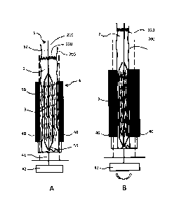
Figures m and 9B:
Figures 9A and 93 show a provision device according to a
fifth embodiment according to embodiments of the invention.
The provision device substantially corresponds to that of
=
figures 3A and 3B, in which the crimping jaws 40 of the
crimping apparatus 4 are within the storage space and hence
within the inert filling 2. A protective sheath 230, which
surrounds the stent 3, is provided between the jaws 40 and
the stent 3 over the entire length 1 of the stent. Hence the
jaws 40 do not come to rest directly on the surface 35 of the
stent when the stent is being compressed. The protective
sheath 230 can be inserted together with the stent during the
introduction thereof into the storage space. However, it can
also be fixedly attached to the elements of the crimping
apparatus or be arranged thereon in a replaceable fashion.
Figure m shows the provision device with an opened
crimping apparatus 4, with the stent being in an expanded
state. The crimping apparatus 4 is closed in
_ _ _________________________________________________ - =
_30
CA 2729879 2017-02-21
WO 2010/000079 - 35 - PCT/CH2009/000189
figure 9B and the stent was crimped onto the balloon 50.
Figure 10:
Figure 10 shows a provision device according to the
fifth embodiment using a self-expanding stent 3 and a
tube catheter 6, in which a protective sheath 230 once
again surrounds the stent 3. The stent is compressed
analogously to the procedure described with reference to
figures 5A to 5E. As soon as the jaws 40 are reopened
after the crimping procedure, the protective film 230
also re-dilates to the extent that the outer tubing 68
can be pushed through between the protective sheath 230
and the stent surface 35 until the stent is accommodated
in the catheter. Here the protective sheath 230 remains
outside of the catheter.
In the illustrated embodiments, use is made of a
crimping apparatus with jaw elements that act on the
stent for the purpose of compression. However, in
principle other crimping apparatuses are also suitable
for use in the provision device according to the
invention, e.g. as illustrated in the description
relating to the prior art.
In order to carry out the method according to
embodiments of the invention, the stent may also be
completely removed from its inert envelope and supplied
to a crimping apparatus, which compresses the stent
outside of the inert envelope, provided the period of
time during which the stent is not protected by the
inert envelope does not permit significant
recontamination. A provision device according to
embodiments of the invention in principle also allows
such a process.
CA 02729879 2011-01-04
WO 2010/000079 - 36 -
PCT/CH2009/000189
LIST OF REFERENCE SIGNS
1 Storage space 230 Protective sheath
2 Filling
3 Stent 1 Length of the stent
4 Crimping apparatus d Stent diameter
Balloon catheter
6 Tube catheter
Base
11 Cover
12 Container
13 Support
Axis
31 Proximal end
32 Distal end
33 Webs
34 Stent lumen
35 Surface
40 Jaws
41 Shaft
42 Activator
43 Guide mandrel
50 Balloon
51 Region of the stent
52 Shaft
53 Guide wire lumen
54 Dilation lumen
55 Tip
61 Region of the stent
62 Shaft
63 Guide wire lumen
65 Tip
66 Inner tubing
67 Support tubing
68 Outer tubing
69 Stop
200 Storage space
210 Opening
220 Filling level