Note: Descriptions are shown in the official language in which they were submitted.
CA 02731092 2011-01-14
PCT/EP2009/058681 - 1 -
2008P06753W0US
Description
Axial turbomachine with low tip clearance losses
The invention refers to an axial turbomachine which has low tip
clearance losses.
An axial turbomachine has a casing and a rotor which is
enclosed by the casing. The
rotor has a hub contour which
together= with the inner contour of the casing forms a flow
passage through the axial turbomachine. The rotor has a
multiplicity of rotor stages which are formed in each case by a
rotor blade cascade. The
rotor blade cascades have a
multiplicity of rotor blades which by one of their ends are
fastened in each case on the rotor on the hub side and by their
other end point radially outwards. A blade tip, which faces
the inner side of the casing and is arranged directly adjacent
thereto, is formed at this other end of the rotor blade. The
distance between each blade tip and the inner side of the
casing is formed as a radial gap which is dimensioned in such a
way that on the one hand the blade tips do not rub against the
casing during operation of the axial turbomachine and on the
other hand the leakage flow through the radial gap, which
ensues during operation of the axial turbomachine, is as low as
possible. So that the axial turbomachine has high efficiency,
it is desirable that the leakage flow through the radial gap is
as low as possible.
If the axial turbomachine is installed in an aero engine, the
casing is of a filigree construction in order to have a weight
which is as low as possible. On the other hand, the rotor is
solidly constructed in order to be able to withstand the
pressure stresses and temperature stresses during operation of
the axial turbomachine. The
rotor blades are less solidly
constructed in comparison to the rotor and are mounted on the
rotor.
CA 02731092 2011-01-14
PCT/EP2009/058681 - 2 -
2008P06753W0US
During operation of the axial turbomachine, the inner side of
the csing and the rotor blades are in contact with hot gas,
the casing having extensive contact with the hot gas on its
inner side. Due to
the fact that the casing is of a more
filigree design than the rotor, the rotor heats up more slowly
than the casing. This
has the result that for startup and
shutdown of the axial turbomachine the rotor and the casing
have different rates of thermal expansion so that during
startup and shutdown of the axial turbomachine the height of
the radial gap, which is formed between the blade tips of the
rotor blades and the inner side of the casing, changes. In
this case, the radial gap is large during startup and small
during shutdown. So that during shutdown the blade tips of the
rotor blades do not butt against the casing and become damaged,
the radial gap is provided with a minimum height which is
dimensioned in such a way that during shutdown of the axial
turbomachine the blade tips seldom, if ever, come into contact
with the casing. This has the result that provision is made
for a correspondingly dimensioned radial gap at the blade tips.
On the other hand, especially during startup of the axial
turbomachine, the radial gap is to be formed only large enough
for a reduction of the power density and the efficiency of the
axial turbomachine, brought about by the leakage flow, to be
kept within acceptable limits.
Modern rotor blades have a very high aerodynamic efficiency
which is achieved as a result of a high pressure load of the
rotor blades. Brought about by this high pressure load, the
leakage flow through the radial gap is particularly high so
that as a result of the leakage flow the overall efficiency of
the rotor blade is seriously impaired.
Particularly in the
case of rotor blades with small overall height and large radial
gaps, about 50% of the overall loss of the rotor blades is
caused by the leakage flow. A reduction of the leakage flow
brings about an improvement of the overall efficiency of the
rotor blade.
CA 02731092 2015-12-10
54106-691
- 3 -
It is customarily known to reduce the leakage flow for example
by means of an "active-clearance control" device. With the
"active-clearance control" device, the casing is cooled during
startup and heated up during shutdown so that the rate of
thermal expansion of the casing is adapted to that of the rotor
blades. Furthermore, for reducing the leakage flow a special
profiling of the blade tips, such as the forming of a knife-
blade-like blade tip, is known from US 4,738,586.
A further blade tip, which is contoured in the direction of the
span of the rotor blade, is known from EP 675 290 A2. The
blade tip and the oppositely disposed passage wall are
contoured corresponding to each other, the passage wall having
an encompassing recess and the blade tip having a radial tip
extension conforming to the recess. As a result of this
measure, a quick reduction of the gas velocity in the region of
the recess can be achieved, as a result of which the strength
of shock waves is weakened.
A further blade-tip contouring and passage-wall contouring is
gathered from FR 996967.
It is the object of the invention to create an axial
turbomachine which has high aerodynamic efficiency. A further
object of the invention is the provision of a rotor blade for
it.
According to an embodiment, there is provided an axial
turbomachine with a rotor blade cascade which is formed from
rotor blades each having a leading edge and a radially outer,
freestanding blade tip, and an annulus wall, encasing the rotor
blade cascade, with an annulus inner side by which the annulus
wall is arranged directly adjacently to the blade tips, forming
CA 02731092 2015-12-10
54106-691
- 3a -
a radial gap between the contours of the blade tips and the
annulus inner side, wherein inside an axial section of the
annulus inner side lying opposite the blade tip, the annulus
wall, on the annulus inner side, has at least one encompassing
first radial recess, with a first and a second curvature
section, which along the principal throughflow direction of the
axial turbomachine is arranged at a constant radial distance
from the contours of the blade tips which correspond to the
annulus inner side, wherein in the principal throughflow
direction of the axial turbomachine the progression on the
annulus inner side has at least one third curvature section
adjoining the second curvature section and one fourth curvature
section adjoining the third curvature section, wherein the
first curvature section is delimited from the second curvature
section by a first inflection point, the second curvature
section is delimited from the third curvature section by a
second inflection point and the third curvature section is
delimited from the fourth curvature section by a third
inflection point, wherein the curvatures of adjacent curvature
sections have different signs.
According to another embodiment, there is provided a rotor
blade for an axial turbomachine, having a leading edge and a
radially outer, freestanding blade tip, which at its blade tip
has at least one first radial projection with a first curvature
section and a second curvature section, wherein along a profile
chord of the rotor blade, the blade tip has at least one third
curvature section adjoining the second curvature section and
one fourth curvature section adjoining the third curvature
section, wherein the first curvature section is delimited from
the second curvature section by a first inflection point, the
second curvature section is delimited from the third curvature
CA 02731092 2015-12-10
54106-691
- 3b -
section by a second inflection point and the third curvature
section is delimited from the fourth curvature section by a
third inflection point, wherein the curvatures of adjacent
curvature sections have different signs.
The profiling of the rotor blade of the axial turbomachine
according to the invention can be of a conventional type. The
radial projections of the rotor blade extend parallel to the
radial recess of the annulus inner side in the principal
throughflow direction of the axial turbomachine so that
CA 02731092 2011-01-14
PCT/EP2009/058681 - 4 -
2008P06753W0US
the radial gap has a uniform and wave-like progression. The
annulus inner side and blade airfoil tip - and correspondingly
also the radial gap - which are formed in the style of a double
wave, comprise in each case at least four curvature sections
which are delimited by inflection points, wherein the
curvatures of adjacent curvature sections have different signs.
As a result, the leakage flow which ensues through the radial
gap during operation of the axial turbomachine is accelerated
and decelerated alternately.
As a result of the acceleration and deceleration, the
throughflow velocity and the direction of the leakage flow is
altered so that a gap vortex, which is formed during mixing of
the leakage flow with the principal flow, is prevented in the
initiation phase and in propagation. Consequently, the effect
of the flow through the rotor blade cascade being homogenous
and low in loss is advantageously achieved, as a result of
which the efficiency of the rotor blade cascade, and therefore
of the axial turbomachine, is high.
The gap, which is constant in its size, has a unifoLm, non-
abruptly changing progression along the principal flow
direction so that the flow in the region of the blade tip is
low in loss.
Brought about by the reduced influence of the leakage flow upon
the principal flow, in addition the work conversion of the
rotor is high and the incident flow of a stator blade which
lies downstream of the rotor blade is improved. As a result, a
misaligned incident flow of this stator blade is reduced and/or
the stator blade can have a simpler shape.
The mass flow of the leakage flow and its unfavorable effect
upon the overall efficiency of the rotor blade cascade are
advantageously reduced. As a result, an improved aerodynamic
quality of the rotor blade cascade ensues without having to
provide additional constructional measures.
CA 02731092 2011-01-14
PCT/EP2009/058681 - 5 -
2008P06753W0US
In this case, the radial distance of the radial recess from the
contours of the blade tips along the principal flow direction
of the axial turbomachine is constant.
Furthermore, it is preferred that the first curvature section
is located in that region of the annulus inner side which lies
opposite the region of a front half of the profile chord of the
blade airfoil tip, as seen from the leading edge. Moreover, it
is preferred that the maximum of the first radial recess is
located in that region or at that point which lies opposite at
10% to 30%, preferably at 20%, of the profile chord, as seen
from the leading edge.
Therefore, the radial projection and the radial recess are
advantageously located in the region of the highest pressure
load of the blade tip of the conventionally profiled rotor
blade so that the leakage flow through the radial gap is
reduced.
Furthermore, it is preferred that the curvature sections are
formed in such a way that in the principal throughflow
direction of the axial turbomachine the progression of the
radial gap extends essentially in an edge-free and step-free
manner. In this case, provision can be made for even more than
four curvature sections both in the annulus inner side and at
the blade airfoil tip in order to reduce the leakage flow
through the radial gap.
It is preferred that upstream of the first curvature section,
downstream of the fourth curvature section and/or downstream of
a curvature section adjoining it, provision is made for an
additional section on the annulus inner side or at the blade
airfoil tip, the progression of which is straight in the
principal flow direction of the axial turbomachine.
CA 02731092 2011-01-14
PCT/EP2009/058681 - 6 -
2008P06753WOUS
Alternatively, it is preferred that the additional section, or
the additional sections, is or are conical in the principal
throughflow direction of the axial turbomachine.
As a result, a gentle transition from the radial recess or from
the radial projections downstream to the trailing edge of the
rotor blade is achieved so that the flow in the region of the
blade tip is low in loss.
It is preferred that the first inflection point, as seen in the
principal flow direction of the axial turbomachine and from the
leading edge, is located at 5% to 15%, preferably at 10%, of
the chord length of the blade, and/or the base of the radial
recess is located at 15% to 25%, preferably at 20%, of the
chord length of the rotor blade.
In principle, the contour of the blade airfoil tip and that of
the annulus inner side opposite it are constantly in
conformance so that both contours are to be identically
described. Therefore, the occurring advantages which apply to
the axial turbomachine correspondingly also apply to a rotor
blade.
The axial turbomachine is preferably a compressor in a
stationary gas turbine, in an aero engine, in a process
compressor, in a fan, in a blower, in a steam pressure turbine,
in a hydraulic turbine and/or in a pump.
The invention is explained in the following text, based on a
preferred embodiment of an axial compressor according to the
invention with reference to the attached schematic drawings.
= In the drawing:
Fig. 1 shows a side view of a casing section of a first
embodiment of the axial compressor according to the invention,
CA 02731092 2011-01-14
PCT/EP2009/058681 - 7 -
2008P06753W0US
Fig. 2 shows a perspective view of a rotor blade tip of the
embodiment from Fig. 1 and
Fig. 3 shows a side view of the first embodiment of a casing of
the axial compressor according to the invention.
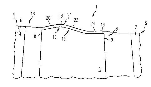
As is apparent from Figs. 1 to 3, an axial compressor 1 has a
rotor 2 which has a rotor blade cascade which is formed from a
multiplicity of rotor blades 3. The
axial compressor 1 is
exposed to throughflow from left to right, as seen in Figures 1
and 3.
Furthermore, the axial compressor 1 has a first stator 4
upstream of the rotor blade 3 and a second stator 5 downstream
of the rotor blade 3. The
first stator 4 is formed from a
multiplicity of first stator blades 6 and the second stator 5
is formed from a multiplicity of second stator blades 7.
The rotor blade 3 has a leading edge 8 on its end facing
upstream and a trailing edge 9 on its end facing downstream,
wherein the one side between the leading edge 8 and the
trailing edge 9 is the pressure side 10 and the other side
between the leading edge 8 and the trailing edge 9 is the
suction side 11 of the rotor blade 3. A rectilinear profile
chord, with a standard chord length of 100%, extends from the
leading edge 8 to the trailing edge 9, wherein the starting
point, equating to 0% of the chord length of the profile chord,
is located at the leading edge and the end point, equating to
100% of the chord length of the profile chord, is located at
the trailing edge.
The rotor blade 3 is enclosed radially on the outside by an
annulus wall 13, the annulus wall 13 having an annulus inner
side 14 which faces the rotor blade 3. The rotor blade 3 is
fastened by its radially inner longitudinal end and is
freestanding by its radially outer longitudinal end, a blade
CA 02731092 2011-01-14
PCT/EP2009/058681 - 7a -
2008P06753W0US
tip 15 being formed at the freestanding end. A gap 16 is
provided between the
CA 02731092 2011-01-14
PCT/EP2009/058681 - 8 -
2008P06753W0US
annulus inner side 14 and the blade tip 15.
The blade tip 15, on its side facing the annulus inner side 14,
is provided with a radial projection 18, the maximum radial
extent of which is located at 20% of the chord length of the
profile chord of the blade 3. Following the progression of the
blade tip 15, in a section of the annulus inner side 14 which
lies opposite the blade tip 15, provision is made in the
annulus wall 13 on the annulus inner side 14 for a radial
recess 17 which, as seen in Figs. 1 and 3, extends from left to
right parallel to the radial projection 18. The radial recess
17 has a base 12 which is arranged radially on the outside
level with the maximum radial extent of the radial projection
18.
The radial recess 17 is formed in an encompassing manner in the
annulus wall 13. Consequently, when the rotor 2 rotates around
the rotational axis 28, each rotor blade 3 can rotate with its
radial projection 18 engaging in the radial recess 17.
As seen in the principal flow direction of the axial compressor
1, the radial recess 17 and, similarly to it, the radial
projection 18, are formed according to a first embodiment from
four curvature sections 19, 21, 23, 25, wherein the curvature
sections 19, 21, 23, 25 in each case have a curvature, the sign
of the curvatures changing from curvature section to curvature
section. The curvature sections 19, 21, 23, 25 are arranged in
series, wherein the first curvature section 19 is delimited
from the second curvature section 21 by a first inflection
point 20.= Furthermore, the second curvature section 22 is
separated from the third curvature section 23 by a second
inflection point 22. The third curvature section 23 is
delimited from the fourth curvature section 25 by a third
inflection point 24. As a result of the
CA 02731092 2011-01-14
PCT/EP2009/058681 - 9 -
2008P06753W0US
series-arrangement of the curvature sections 19, 21, 23, 25 and
the inflection points 20, 22, 24 lying inbetween, the gap 16
between the blade tip 15 and the annulus inner side 14 is of a
wave-like form.
In Fig. 2, the radial limit of a conventional blade tip is
shown by the line 27 so that the radial length extension is
noticeably brought about by the provision of the radial
projection 18.
In Fig. 3, the progression of the annulus inner side 14 in
relation to a rotational axis 28 of the axial compressor 1
according to the first embodiment is shown. Upstream of the
first curvature section 19 and/or downstream of the fourth
curvature section 25, the progression of the annulus inner side
14, at least in that region which lies opposite the blade
airfoil tip 15, is conical and therefore rectilinear, in order
to maintain a passage contraction.
Naturally, it is possible that the progression of the annulus
inner side 14 and correspondingly the blade airfoil tip 15 do
not have only four curvature sections but even more curvature
sections.