Note: Descriptions are shown in the official language in which they were submitted.
CA 02731635 2011-02-11
Attorney Docket No. 3601-000036/US
BOW SIGHT
CROSS-REFERENCE TO RELATED APPLICATIONS
[0001] This application claims the benefit of U.S. Provisional
Application No. 61/331,106, filed on May 4, 2010. The entire disclosure of the
above application is incorporated herein by reference.
FIELD
[0002] The present disclosure relates to sights and more particularly to
a sight incorporating an optical fiber for use in conjunction with a weapon.
BACKGROUND
[0003] This section provides background information related to the
present disclosure which is not necessarily prior art.
[0004] Sights are often used in conjunction with weapons to aid a user
in properly aligning the weapon with a target. For example, hunters and
competitive archers typically use a sight in conjunction with a bow to
properly
align the bow with a target. Proper alignment of the bow with the target is
essential to ensure that an arrow fired by the bow impacts the target at a
desired
location.
[0005] Conventional sights may be rigidly mounted relative to a frame
of a weapon such as, for example, a bow to fix a position of the sight
relative to
the weapon. As such, alignment of the sight with a target likewise aligns the
weapon relative to the target and increases the likelihood that a projectile
shot
from the weapon will properly strike the target at a desired location.
1
CA 02731635 2011-02-11
Attorney Docket No. 3801-000036/US
[0006] An aiming point may be used to aid a user in aligning the sight
with a target. In one configuration, a post is fixed relative to the sight and
serves
as the aiming point. In another configuration, a distal end of an illuminated,
optical fiber is used in conjunction with a support structure and functions as
the
aiming point.
[0007] While conventional sights provide structure that aids a user in
aligning a weapon relative to a target, such sights are costly and complicated
to
manufacture. Furthermore, while some sights provide a user with an illuminated
aiming point, such sights are somewhat fragile and difficult to repair, as the
fiber
is typically exposed to ambient conditions to allow a distal end of the fiber
to
serve as an aiming point. Such exposed fibers must be supported by a structure
of the sight, thereby adding to the overall cost, weight, and complexity of
the
sight.
SUMMARY
[0008] This section provides a general summary of the disclosure, and
is not a comprehensive disclosure of its full scope or all of its features.
[0009] A sight is provided and may include a housing having a first
end, a second end, and an opening extending along a longitudinal axis between
the first end and the second end. The sight may also include an optical fiber
supported by the housing and a sighting pin having an aiming point extending
into the opening of the housing and receiving light from the optical fiber to
2
CA 02731635 2011-02-11
Attorney Docket No. 3801-000036/US
illuminate the aiming point. The sighting pin may include a longitudinal axis
disposed substantially perpendicular to the longitudinal axis of the opening.
[0010] In another configuration, a sight is provided and may include a
housing having a first end, a second end, and an opening extending along a
longitudinal axis between the first end and the second end. The sight may also
include an optical fiber supported by the housing and a sighting pin extending
into the opening of the housing and in optical communication with the optical
fiber. The sighting pin may include an aiming point disposed at a distal end
thereof that opposes an inner surface of the housing and is illuminated with
light
received from the optical fiber.
[0011] Further areas of applicability will become apparent from the
description provided herein. The description and specific examples in this
summary are intended for purposes of illustration only and are not intended to
limit the scope of the present disclosure.
DRAWINGS
[0012] The drawings described herein are for illustrative purposes only
of selected embodiments and not all possible implementations, and are not
intended to limit the scope of the present disclosure.
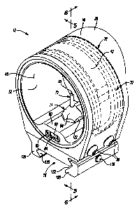
[0013] FIG. 1 is a perspective view of a sight in accordance with the
principles of the present disclosure;
[0014] FIG. 2 is a partial-front view of the sight of FIG. 1 detailing a
level and attachment portion of the sight;
3
CA 02731635 2011-02-11
Attorney Docket No. 3801-000036/US
[0015] FIG. 3 is a top view of the sight of FIG. 1;
[0016] FIG. 4 is an exploded view of the sight of FIG. 1;
[0017] FIG. 5 is a cross-sectional view of the sight of FIG. 1 taken
along line 5-5;
[0018] FIG. 6 is a cross-sectional view of the sight of FIG. 1 taken
along line 6-6;
[0019] FIG. 7 is a perspective view of a sight in accordance with the
principles of the present disclosure incorporating an illumination system;
[0020] FIG. 8 is an exploded view of the illumination system of FIG. 7;
[0021] FIG. 9 is a perspective view of a sight in accordance with the
principles of the present disclosure;
[0022] FIG. 10 is a rear view of the sight of FIG. 9;
[0023] FIG. 11 is a side view of the sight of FIG. 9; and
[0024] FIG. 12 is a bottom view of the sight of FIG. 9.
[0025] Corresponding reference numerals indicate corresponding parts
throughout the several views of the drawings.
DETAILED DESCRIPTION
[0026] Example embodiments will now be described more fully with
reference to the accompanying drawings.
[0027] Example embodiments are provided so that this disclosure will
be thorough, and will fully convey the scope to those who are skilled in the
art.
Numerous specific details are set forth such as examples of specific
4
CA 02731635 2011-02-11
Attorney Docket No. 3801-000036/US
components, devices, and methods, to provide a thorough understanding of
embodiments of the present disclosure. It will be apparent to those skilled in
the
art that specific details need not be employed, that example embodiments may
be embodied in many different forms and that neither should be construed to
limit
the scope of the disclosure. In some example embodiments, well-known
processes, well-known device structures, and well-known technologies are not
described in detail.
[0028] The terminology used. herein is for the purpose of describing
particular example embodiments only and is not intended to be limiting. As
used
herein, the singular forms "a," "an," and "the" may be intended to include the
plural forms as well, unless the context clearly indicates otherwise. The
terms
"comprises," "comprising," "including," and "having," are inclusive and
therefore
specify the presence of stated features, integers, steps, operations,
elements,
and/or components, but do not preclude the presence or addition of one or more
other features, integers, steps, operations, elements, components, and/or
groups
thereof. The method steps, processes, and operations described herein are not
to be construed as necessarily requiring their performance in the particular
order
discussed or illustrated, unless specifically identified as an order of
performance.
It is also to be understood that additional or alternative steps may be
employed.
[0029] When an element or layer is referred to as being "on," "engaged
to," "connected to," or "coupled to" another element or layer, it may be
directly
on, engaged, connected or coupled to the other element or layer, or
intervening
elements or layers may be present. In contrast, when an element is referred to
CA 02731635 2011-02-11
Attorney Docket No. 3801-000036/US
as being "directly on," "directly engaged to," "directly connected to," or
"directly
coupled to" another element or layer, there may be no intervening elements or
layers present. Other words used to describe the relationship between elements
should be interpreted in a like fashion (e.g., "between" versus "directly
between,"
"adjacent" versus "directly adjacent," etc.). As used herein, the term
"and/or"
includes any and all combinations of one or more of the associated listed
items.
[0030] Although the terms first, second, third, etc. may be used herein
to describe various elements, components, regions, layers and/or sections,
these
elements, components, regions, layers and/or sections should not be limited by
these terms. These terms may be only used to distinguish one element,
component, region, layer or section from another region, layer or section.
Terms
such as "first," "second," and other numerical terms when used herein do not
imply a sequence or order unless clearly indicated by the context. Thus, a
first
element, component, region, layer or section discussed below could be termed a
second element, component, region, layer or section without departing from the
teachings of the example embodiments.
[0031] Spatially relative terms, such as "inner," "outer," "beneath,"
"below," "lower," "above," "upper," and the like, may be used herein for ease
of
description to describe one element or feature's relationship to another
element(s) or feature(s) as illustrated in the figures. Spatially relative
terms may
be intended to encompass different orientations of the device in use or
operation
in addition to the orientation depicted in the figures. For example, if the
device in
the figures is turned over, elements described as "below" or "beneath" other
6
CA 02731635 2011-02-11
Attorney Docket No. 3801-000036/US
elements or features would then be oriented "above" the other elements or
features. Thus, the example term "below" can encompass both an orientation of
above and below. The device may be otherwise oriented (rotated 90 degrees or
at other orientations) and the spatially relative descriptors used herein
interpreted
accordingly.
[0032] With reference to the figures, a sight 10 is provided. The sight
may include a housing 12, an illumination system 14, and an attachment
assembly 16. The housing 12 and attachment assembly 16 cooperate to position
the illumination system 14 relative to an external structure (not shown) to
allow
the illumination system 14 to aid a user in properly aligning the external
structure
relative to a target (not shown). In one configuration, the external structure
is a
weapon such as, for example, a bow, whereby the attachment assembly 16
attaches and positions the housing 12 relative to the bow and the illumination
system 14 provides an aiming point for aiding a user in aligning the bow (via
sight
10) relative to a target. The sight 10 may also be used with a mount such as
the
bow-sight mount disclosed in Assignee's commonly owned U.S. patent
application titled "Bow-Sight Mount" filed concurrently herewith and
incorporated
herein by reference. While the sight 10 is described as being associated with
a
bow, the sight 10 could be used to align virtually any structure relative to a
target
and is not limited solely for use in conjunction with a weapon.
[0033] The housing 12 may include a first portion 18, a second portion
20, and a third portion 22 recessed from and disposed between the first
portion
18 and the second portion 20. The first portion 18 may include a front face 24
7
CA 02731635 2011-02-11
Attorney Docket No. 3801-000036/US
opposing a target when in use, as well as a lip 26 extending generally over an
opening 28 of the housing 12. The lip 26 is positioned and extends farther
from
the opening 28 than does the front face 24 to shield the opening 28 from
ambient
light to prevent ambient light from interfering with operation of the
illumination
system 14.
[0034] The second portion 20 may be disposed on an opposite end of
the housing 12 from the first portion 18 and may include a recess 30 having a
substantially circular shape as well as a front face 32. The recess 30 may be
recessed from the front face 32 and may receive a generally circular alignment
tape 34 therein. The alignment tape 34 may include a substantially circular
shape and may be formed from a fluorescent or other highly visible material
that
aids a user in aligning the housing 12 with a target and/or identifying the
opening
28 of the housing 12. In one configuration, the alignment tape 34 includes an
adhesive (not shown) that adheres the alignment tape 34 to the second portion
20 of the housing 12 generally within the recess 30. Once the alignment tape
34
is installed and received within the recess 30, an outer surface 36 of the
alignment tape 34 may be substantially flush with the front face 32 (FIG. 5).
[0035] The third portion 22 may be recessed from an outer surface 38
of the first portion 18 and from an outer surface 40 of the second portion 20.
A
rib 42 may be disposed within the third portion 22 between the first portion
18
and the second portion 20 and may define a pair of channels 44. In one
configuration, the rib 42 is disposed at a central location of the third
portion 22
such that the channels 44 defined by the rib 42 in cooperation with the first
8
CA 02731635 2011-02-11
Attorney Docket No. 3801-000036/US
portion 18 and the second portion 20 include a substantially identical width
(FIG. 5).
[0036] The third portion 22 may also include an opening 46 disposed at
an opposite end of the housing 12 than the rib 42. The opening 46 may be
defined generally between the first portion 18 and the second portion 20 and
may
at least partially receive a portion of the illumination system 14 and
attachment
assembly 16 therein.
[0037] The first portion 18, second portion 20, and third portion 22 may
cooperate to provide the housing 12 with a substantially uniform inner surface
48
and a ledge 50 extending generally between the front face 24 of the first
portion
18 and the front face 32 of the second portion 20. As described, the inner
surface 48 of the housing 12 provides the housing 12 with a substantially
circular
shape extending between the front face 24 of the first portion 18 and the
front
face 32 of the second portion 20. The circular shape defined by the inner
surface
48 may terminate at the ledge 50, which may extend into an open area 52
generally towards the inner surface 48. The ledge 50 may include an aperture
54 in communication with a threaded bore 56 that cooperate to position a
portion
of the illumination system 14 relative to the housing 12. The aperture 54 and
threaded bore 56 may be in communication with the opening 46 of the third
portion 22 to allow a portion of the illumination system 14 to be inserted
into the
aperture 54 and threaded bore 56 at the opening 46 generally between the first
portion 18 and the second portion 20.
9
CA 02731635 2011-02-11
Attorney Docket No. 3801-000036/US
[0038] The ledge 50 may additionally include a pocket 58 (FIG. 5) and
a window 60 in fluid communication with the pocket 58. The pocket 58 may be
sized to matingly receive a bubble level 62 therein to aid a user in properly
aligning the housing 12 and, thus, the sight 10 relative to an external
structure
and/or to ensure that the housing 12 is level: Because the window 60 is in
fluid
communication with the pocket 58, the bubble level 62 is visible through the
window 60 once inserted into the pocket 58.
[0039] As shown in FIG. 2, the window 60 may be formed in the front
face 32 of the second portion 20 such that the window 60 fully encases the
bubble level 62. Encasing the bubble level 62 such that the housing 12 fully
surrounds the bubble level 62 at the window 60 protects the bubble level 62
and
minimizes the viewable portion of the bubble level 62 to only that which is
required by the user. The window 60 may include a substantially oval shape or,
alternatively, may include an alignment point 64 to aid a user in aligning a
bubble
66 of the bubble level 62 relative to the housing 12 and between two
graduation
marks 68 formed in or on the bubble level 62 (FIG. 2).
[0040] With particular reference to FIGS. 4-8, the illumination system
14 is shown and may include an optical fiber 70, a sighting pin 72, a fitting
assembly 74, and a cover 76. The optical fiber 70 may include a diameter of
approximately two millimeters (0.079 inches) and may be formed from virtually
any color. For example, the optical fiber 70 may be formed from green, red, or
orange fibers to provide the sighting pin 72 with a desired color. The optical
fiber
70 may be formed in a "racetrack" configuration, whereby the optical fiber 70
is
CA 02731635 2011-02-11
Attorney Docket No. 3801-000036/US
wound in a substantially oval or serpentine shape prior to being inserted into
the
channels 44 of the housing 12 (FIG. 5). While the optical fiber 70 is
described as
being wound into a substantially oval or serpentine shape prior to being
positioned within the channels 44, the optical fiber 70 could 4ternatively be
formed into the racetrack" configuration while concurrently installing the
optical
fiber 70 in the channels 44. Specifically, the optical fiber 70 may be wound
around the rib 42 and within the third portion 22 of the housing 12 into the
shape
shown in FIG. 4. In either configuration, the rib 42 may cooperate with the
first
portion 18 and the second portion 20 of the housing 12 to properly position
the
optical fiber 70 within the third portion 22 of the housing 12.
[0041] In one configuration, the width of each channel 44 is determined
by a width of three strands of the optical fiber 70, as shown in FIG. 5. For
example, if the optical fiber 70 includes a diameter substantially equal to
two
millimeters, a width of each channel 44 may be approximately equal to six
millimeters such that when the optical fiber 70 is positioned within each
channel
44, the optical fiber 70 is held in place within each channel 44 by a surface
of the
rib 42 and a surface of either, the first portion 18 or the second portion 20
of the
housing 12.
[0042] The portion of the optical fiber 70 received generally within the
channels 44 may constitute a wound portion 78 (FIG. 4) that begins at a first
end
80 and terminates at a second end 82. The second end 82 may be received
within the opening 46 of the third portion 22 such that the second end 82
extends
11
CA 02731635 2011-02-11
Attorney Docket No. 3801-000036/US
into the opening 46 and opposes the sighting pin 72 to illuminate the sighting
pin
72, as will be described further below.
[0043] The cover 76 may be formed from a transparent material that
protects the optical fiber 70 from damage while concurrently allowing ambient
light to be received by the optical fiber 70. The cover 76 may be received
within
the third portion 22 of the housing 12 such that an outer surface 84 of the
cover
76 is substantially flush with the outer surfaces 38, 40 of the first and
second
portions 18, 20 of the housing 12 when the cover 76 is installed. The cover 76
may be attached to the housing 12 by a series of fasteners 86 that extend
through apertures 88 of the cover 76 and are threadably received within bores
138 of the housing 12 and/or attachment assembly 16. When the threaded
fasteners 86 are received within the apertures 88 and secured to the housing
12
and/or attachment assembly 16, the cover 76 is fixedly attached to the housing
12 and restricts removal of the optical fiber 70 from the channels 44. In this
regard, the cover 76 not only protects the optical fiber 70 but also aides in
restricting removal of the optical fiber 70-inadvertent or otherwise-from the
channels 44.
[0044] The sighting pin 72 may be at least partially received within the
aperture 54 of the ledge 50 and may extend upwardly from the ledge 50 toward
the inner surface 48 of the housing 12. The sighting pin 72 may be a clear
fiber
being relatively rigid when compared to the optical fiber 70. Alternatively,
the
sighting pin 72 could include the same or similar rigidity as the optical
fiber 70 if
the sighting pin 72 and optical fiber 70 include approximately the same
diameter.
12
CA 02731635 2011-02-11
Attorney Docket No. 3801-000036/US
Regardless of the particular diameter of the optical fiber 70 and sighting pin
72,
the sighting pin 72 may be sufficiently rigid such that the sighting pin 72 is
self-
supporting, as will be described further below. The sighting pin 72 may be
polished such that a tip 90 of the sighting pin 72 appears as a colored
triangle
when coupled to and receiving light from the optical fiber 70, as will be
described
in greater detail below. The sighting pin 72 and associated tip 90 may be of
the
type discloses in assignee's commonly owned U.S. Patent No. 5,924,234 issued
on July 20, 1999, the disclosure of which is incorporated herein by reference.
[0045] While the sighting pin 72 is described as including a tip 90 at a
distal end of the sighting pin 72 having a substantially triangular shape, the
distal
end of the sighting pin 72 could include a different shape to provide an
aiming
point other than a triangular-aiming point. For example, in one configuration,
the
tip 90 of the sighting pin 72 may be formed such that the tip 90 provides an
oval,
circular, or "D" shaped aiming point for use by the user in aligning the tip
90 with
a target. Regardless of the particular construction of the tip 90, the
sighting pin
72 may be formed from a clear fiber that receives light from the optical fiber
70
for illumination of the tip 90. Illumination of the tip 90 provides the user
with an
illuminated aiming point 92 for use by a user in aligning an external
structure
such as, for example, a bow, with a target.
[0046] Regardless of the particular configuration of the tip 90 of the
sighting pin 72, the sighting pin 72 may include a diameter similar to the
diameter
of the optical fiber 70. For example, the sighting pin 72 may include a
diameter
substantially equal to two millimeters (0.079 inches) such that the diameter
of the
13
CA 02731635 2011-02-11
Attorney Docket No. 3801-000036/US
sighting pin 72 approximates or is identical to that of the optical fiber 70.
Providing the optical fiber 70 with a diameter approximating two millimeters
enhances the ability of the optical fiber 70 to gather ambient light.
Likewise,
providing the sighting pin 72 with a diameter approximating two millimeters
allows the sighting pin 72 to maximize the amount of light received from the
optical fiber 70 and, thus, the amount of light used in illuminating the tip
90.
[0047] The fitting assembly 74 may be at least partially disposed within
the aperture 54 of the ledge 50 and may cooperate with the optical fiber 70
and
the sighting pin 72 to position the second end 82 of the optical fiber 70 and
the
sighting pin 72 relative to the open area 52 of the housing 12. The fitting
assembly 74 may include a collar 94, a base 96, a sleeve or pair of sleeves
98,
and a seal member 100. The collar 94 may include a shape approximating that
of a frustum and may include a first bore 102, a second bore 104 adjacent to
the
first bore 102 and having a larger diameter than that of the first bore 102,
and a
threaded bore 106.
[0048] The base 96 may include a bore 108 extending therethrough, a
first threaded portion 110, and a second threaded portion 112 disposed
adjacent
to the first threaded portion 110. The second threaded portion 112 may include
a
larger diameter than the first threaded portion 110 such that an engagement
surface 114 is disposed generally between the first threaded portion 110 and
the
second threaded portion 112.
[0049] In operation, the fitting assembly 74 may cooperate with the
ledge 50 of the housing 12 to position the second end 82 of the optical fiber
70
14
CA 02731635 2011-02-11
Attorney Docket No. 3801-000036/US
and the sighting pin 72 relative to the open area 52 of the housing 12.
Specifically, the base 96 is received generally within the aperture 54 of the
ledge
50 such that the second threaded portion 112 threadably engages the threaded
bore 56 of the aperture 54. When the second threaded portion 112 engages the
threaded bore 56 of the ledge 50, the first threaded portion 110 of the base
96
extends generally through the aperture 54 and into the open area 52 of the
housing 12. The extent to which the first threaded portion 110 extends into
the
open area 52 of the housing 12 may be determined based on the engagement
surface 114 of the base 96. Specifically, as the base 96 is installed in the
housing 12 and is rotated relative to the threaded bore 56, the base 96 moves
relative to the housing 12, thereby causing the first threaded portion 110 of
the
base 96 to extend into the open area 52. The base 96 will continue to move
relative to the housing 12 until the engagement surface 114 contacts a bottom
surface 116 (FIG. 5) of the housing 12 proximate to the aperture 54. Once the
engagement surface 114 contacts the bottom surface 116 of the housing 12, the
base 96 can no longer be rotated relative to the housing 12 to advance the
first
threaded portion 110 farther into the open area 52 of the housing 12.
[0050] Once the engagement surface 114 is in contact with the bottom
surface 116, the first threaded portion 110 of the base 96 may extend through
the
aperture 54 and into the open area 52 of the housing 12. The first threaded
portion 110 may threadably receive the threaded bore 106 of the collar 94 to
retain and position the sighting pin 72 relative to the housing 12 and optical
fiber
70. Specifically, the optical fiber 70 may be received within the bore 108 of
the
CA 02731635 2011-02-11
Attorney Docket No. 3801-000036/US
base 96 and may be positioned by an assembly tool, so the second end 82 is
positioned a desired distance from ledge 50. The optical fiber 70 may be
attached to the base 96 within the bore 108 of the base 96 using an adhesive
such as, for example epoxy, to retain the optical fiber 70 within the base 96.
[0051] The sighting pin 72 may also be received within the bore 108 of
the base 96 and may be positioned and secured within the bore 108 by sleeve
98. The sleeve 98 may be attached to the sighting pin 72 by way of a suitable
adhesive such as, for example, epoxy. The sleeve 98 associated with the
sighting pin 72 is not fixedly attached to the base 96 within the bore 108 to
allow
the sighting pin 72 to be replaced or repaired.
[0052] The sighting pin 72, once received within the bore 108, may be
positioned relative to the second end 82 of the optical fiber 70 such that an
end
118 of the sighting pin 72 opposes the second end 82 of the optical fiber 70.
As
such, light from the optical fiber 70 is permitted to exit the second end 82
of the
optical fiber 70 and is received by the end 118 of the sighting pin 72 for use
by
the sighting pin 72 in illuminating the tip 90 and providing a user of the
sight 10
with the illuminated aiming point 92.
[0053] The sighting pin 72 may be inserted into the bore 108
concurrently with positioning of the collar 94 relative to the base 96. The
sighting
pin 72 may be retained within the second bore 104 of the collar 94 due to
interaction between an outer surface 120 of the sighting pin 72 and the seal
member 100 to allow the sighting pin 72 to move with the collar 94 prior to
the
collar 94 being installed on the base 96.
16
CA 02731635 2011-02-11
Attorney Docket No. 3801-000036/US
[0054] In one configuration, the seal member 100 is an O-ring that is
compressed when the sighting pin 72 is received within the second bore 104 of
the collar 94. Compression of the seal member 100 between the outer surface
120 of the sighting pin 72 and the second bore 104 of the collar 94 allows the
sighting pin 72 to be retained within the collar 94 prior to the collar 94
engaging
the first threaded portion 110 of the base 96.
[0055] When the collar 94 is positioned relative to the first threaded
portion 110 of the base 96, the threaded bore 106 engages the first threaded
portion 110 and the sighting pin 72 is received within the bore 108 of the
base
96. As the collar 94 is rotated relative to the first threaded portion 110 of
the
base 96, the end 118 of the sighting pin 72 is brought into close proximity
with
the second end 82 of the optical fiber 70. Additionally, as the collar 94 is
rotated
relative to the first threaded portion 110, the collar 94 advances toward to
the
ledge 50 and the seal member 100 is compressed between the distal end 99 of
the sleeve 98 and an inner surface of the second bore 104, thereby retaining
the
sighting pin 72 within the collar 94 and restricting movement of the sighting
pin
72 relative to the housing 12.
[0056] in one configuration, the sighting pin 72 may be positioned
relative to the collar 94 such that once the collar 94 is fully installed on
the base
96, the end 118 of the sighting pin 72 is in an abutting relationship with the
second end 82 of the optical fiber 70. In another configuration, a slight gap
(not
shown) may be disposed between the end 118 of the sighting pin 72 and the
second end 82 of the optical fiber 70. Regardless of the particular position
of the
17
CA 02731635 2011-02-11
Attorney Docket No. 3801-000036/US
second end 82 of the optical fiber 70 and the end 118 of the sighting pin 72,
light
from the optical fiber 70 is transmitted to the sighting pin 72 for use by the
sighting pin 72 in illuminating the tip 90.
[0057] The collar 94 may include a series of flats 122 (FIG. 4) for
mating engagement with a tool (not shown) that facilitates rotation of the
collar 94
relative to the base 96. The collar 94 may be rotated by the tool until the
collar
94 engages the ledge 50 such that a portion of the ledge 50 is disposed and
compressed between the collar 94 and the engagement surface 114 of the base
96. Positioning the portion of the ledge 50 between the collar 94 and the base
96
retains the collar 94 and base 96 within the aperture 54. Because the sighting
pin 72 is received within the bores 102, 104 of the collar 94 and retained
therein
due to engagement between the distal end 99 of the sleeve 98, the seal member
100, and the second bore 104 of the collar 94, the sighting pin 72 is likewise
retained within and positioned relative to the open area 52 of the housing 12.
[0058] As described above, the sighting pin 72 is retained within the
first and second bores 102, 104 of the collar 94 due to engagement of the
sleeve
98 and the seal member 100 when the collar 94 is installed on the base 96. As
such, applying a force on the sighting pin 72 substantially along a
longitudinal
axis of the sighting pin 72 prevents removal of the sighting pin 72 from the
collar
94 when the collar 94 is installed on the base 96. However, the sighting pin
72
can be removed from the collar 94 when the collar 94 is removed from the base
96 by applying a force to the sighting pin 72 in a direction generally away
from
the seal member 100. Removal of the sighting pin 72 from the collar 94 permits
18
CA 02731635 2011-02-11
Attorney Docket No. 3801-00o036/US
a user to clean the sighting pin 72 and/or replace a broken or damaged
sighting
pin 72 without having to replace or adjust the optical fiber 70. Furthermore,
allowing replacement of the sighting pin 72 permits a user to use different
sighting pins 72 possibly incorporating tips 90 of different shapes. As
described
above and shown in assignee's commonly-owned U.S. Patent No. 5,924,234,
which is incorporated herein by reference, the distal end of the sighting pin
72
may include any number of shapes that provide the user with an illuminated
aiming point 92 having a desired shape.
[0059] In order to remove the sighting pin 72 from the housing 12, a
tool may engage the flats 122 to rotate the collar 94 relative to the housing
12.
Once the collar 94 disengages the first threaded portion 110 of the base 96, a
force may be applied substantially along a longitudinal axis of the sighting
pin 72
in a direction such that a distal end 99 of the sleeve 98 disengages the seal
member 100. Once the sighting pin 72 is removed, the sighting pin 72 may be
repaired or replaced and then inserted once again first into the threaded bore
106 of the collar 94 and then through the first and second bores 102, 104 of
the
collar 94. The sighting pin 72 is inserted into the first and second bores
102, 104
until the distal end 99 of the sleeve 98 contacts the seal member 100. At this
point, the collar 94 may again threadably engage the first threaded portion
110 of
the base 96 to position the sighting pin 72 within the housing 12. The collar
94
may be rotated until the collar 94 contacts the ledge 50, at which point the
end
118 of the sighting pin 72 contacts the second end 82 of the optical fiber 70
and
the seal member 100 is compressed by the sleeve 98. As described above,
19
CA 02731635 2011-02-11
Attorney Docket No. 3801-000036/US
compressing the seal member 100 via the sleeve 98 retains the sighting pin 72
relative to the collar 94 and, thus, retains the sighting pin 72 relative to
the
housing 12.
[0060] The illumination system 14 may additionally include a Tritium
lamp 124 disposed proximate to the second end 82 of the optical fiber 70. The
Tritium lamp 124 may selectively supply light to the optical fiber 70 to allow
the
optical fiber 70 to illuminate the sighting pin 72. The Tritium lamp 124 may
be
used in low-ambient light conditions where insufficient ambient light is
received
by the optical fiber 70 and the optical fiber 70 is not capable of
sufficiently
illuminating the tip 90 of the sighting pin 72. While the Tritium lamp 124 is
described as being disposed proximate to the second end 82 of the optical
fiber
70, the Tritium lamp 124 could be disposed at any point along the length of
the
optical fiber 70, provided the Tritium lamp 124 provides the optical fiber 70
with
light.
[0061] As described above, the sighting pin 72 may be relatively rigid.
As such, the sighting pin 72 is self-supporting in that additional structure
is not
required to support the tip 90 of the sighting pin 72 relative to the housing
12.
While the sighting pin 72 is.retained and positioned by the fitting assembly
74,
the fitting assembly 74 does not support the tip 90 within the housing 12.
Rather,
because the sighting pin 72 is formed from a relatively rigid and self-
supporting
material, attaching the sighting pin 72 generally at a base of the sighting
pin 72
via the fitting assembly 74 allows the tip 90 to be positioned within the open
area
CA 02731635 2011-02-11
Attorney Docket No. 3801-000036/US
52 of the housing 12 without requiring the tip 90 to be supported by the
fitting
assembly 74 or otherwise.
[0062] While a self-supporting sighting pin 72 is described as being
used in conjunction with the optical fiber 70, the optical fiber 70 could
alternatively be used in conjunction with a relatively flexible fiber 73 to
generate
the illuminated aiming point 92. For example, the second end 82 of the optical
fiber 70 could be in an abutting relationship with an end 75 of the flexible
fiber 73
to provide the flexible fiber 73 with light. The flexible fiber 73 may extend
through
the collar 94 and base 96 in a similar fashion as the sighting pin 72 and may
be
supported by a tube 77. The tube 77 may include a first arm 79 extending
though the collar 94 and base 96, a second arm 81 extending substantially
ninety
degrees (90 ) relative to the first arm 79, and a passageway 83 extending
along
a length of the tube 77 through the first arm 79 and second arm 81.
[0063] The flexible fiber 73 may be a clear fiber such that color of the
light supplied to the illuminated aiming point 92 is dictated by the color of
the
optical fiber 70 and may include a reduced diameter when compared to the
optical fiber 70. While the flexible fiber 73 is described as being a clear
fiber and
of a reduced diameter when compared to the optical fiber 70, the flexible
fiber 73
could include any size and virtually any color. As such, the flexible fiber 73
could
cooperate with the optical fiber 70 to likewise provide the illuminated aiming
point
92 with virtually any color.
[0064] Regardless of the color of the flexible fiber 73, the flexible fiber
73 extends substantially through the first arm 79 and into the second arm 81
21
CA 02731635 2011-02-11
Attorney Docket No. 3801-000036/US
such that the flexible fiber 73 similarly includes a ninety-degree (900) bend.
Positioning the flexible fiber 73 within the tube 77 such that the flexible
fiber 73 is
bent substantially ninety degrees (900) allows a distal end 85 of the flexible
fiber
73 to extend along and in substantially the same direction as a longitudinal
axis
of the second arm 81 (FIGS. 7 and 8). As such, the distal end 85 of the
flexible
fiber 73 may be positioned so as to oppose an opening of the housing 12
defined
by the alignment tape 34 such that the end 85 opposes a user and provides the
illuminated aiming point 92. Because the flexible fiber 73 and tube 77 include
a
substantially circular cross section, the illuminated aiming point 92 likewise
includes a substantially circular shape in this configuration.
[0065] With particular reference to FIGS. 2 and 6, the attachment
assembly 16 will be described in detail. The attachment assembly 16 may
include a bracket 126 and a locking member 128 that cooperate to attach the
housing 12 to the external structure. In one configuration, the external
structure
may include a Picatinny rail or a Weaver rail (neither shown) that cooperates
with
the attachment assembly 16 to attach the housing 12 to the rail. The bracket
126
may include a pocket 130 that cooperates with a pocket 132 of the locking
member 128 such that the pockets 130, 132 cooperate to form a female portion
that matingly receives a male portion of the rail. The bracket 126 may include
an
aperture 134 that receives a fastener 136 and may also include a series of
threaded bores 138 that matingly receive the fasteners 86 to retain the cover
76
relative to the housing 12. The bracket 126 may also include at least one
aperture 127 that receives a fastener 144 to secure the bracket 126 relative
to
22
CA 02731635 2011-02-11
Attorney Docket No. 3801-000036/US
the housing 12. The locking member 128 may include a threaded aperture 140
that threadably receives the fastener 136 and may cooperate with the pocket
130
of the bracket 126 to provide the sight 10 with a female portion that
cooperates
with a male portion of the rail.
[0066] In operation, the sight 10 may be positioned relative to a rail
such that the male portion of the rail is received within the female portion
of the
attachment assembly 16. Specifically, the rail may be received within the
pocket
130 of the bracket 126 and within the pocket 132 of the locking member 128.
Once the rail is received within the pockets 130, 132, the fastener 136 may be
rotated relative to the bracket 126 and the locking member 128. Rotation of
the
fastener 136 relative to the bracket 126 and the locking member 128 causes a
threaded portion 142 of the fastener 136 to engage the threaded aperture 140
of
the locking member 128 to draw the locking member 128 closer to the bracket
126 to retain the male portion of the rail generally within and between the
pocket
130 of the bracket 126 and the pocket 132 of the locking member 128.
[0067] While the sight 10 is described as being used in conjunction
with a Picatinny rail or a Weaver rail, the sight 10 could also be used in
conjunction with virtually any rail. For example, the sight 10 may be used in
conjunction with a dove-tail rail (not shown) extending substantially ninety
degrees (90 ) relative to a Picatinny rail or Weaver rail (FIGS. 9-12). If the
sight
is used in conjunction with such a dove-tail rail, the sight 10 may include an
attachment assembly 16a having a different configuration to accommodate the
dove-tail rail.
23
CA 02731635 2011-02-11
Attorney Docket No. 3601-000036/US
[0068] In view of the substantial similarity in structure and function of
the components associated with the sight 10 with respect to the sight 10a,
like
reference numerals are used hereinafter and in the drawings to identify like
components while like reference numerals containing letter extensions are used
to identify those components that have been modified.
[0069] If the sight 10a is used in conjunction with a dove-tail rail, the
attachment assembly 16a may include a bracket 126a having a passageway 146
shaped and configured to accommodate the dove-tail rail.
[0070] In operation, when the sight 10a is installed on the dove-tail rail,
a male portion of the dove-tail rail is received within the passageway 146.
Once
the sight 10a is properly positioned relative to the dove-tail rail, a series
of set
screws 148 may be rotated to fix a position of the sight 10a relative to the
dove-
tail rail.
[0071] The foregoing description of the embodiments has been
provided for purposes of illustration and description. It is not intended to
be
exhaustive or to limit the invention. Individual elements or features of a
particular
embodiment are generally not limited to that particular embodiment, but, where
applicable, are interchangeable and can be used in a selected embodiment, even
if not specifically shown or described. The same may also be varied in many
ways. Such variations are not to be regarded as a departure from the
invention,
and all such modifications are intended to be included within the scope of the
invention.
24