Note: Descriptions are shown in the official language in which they were submitted.
CA 02731792 2011-01-21
1
{DESCRIPTION}
{Title of Invention}
SUN-AND-PLANET SPEED-UP GEAR
{Technical Field}
{0001}
The present invention relates to sun-and-planet speed-up
gears suitably used for wind turbines etc.
{Background Art}
{0002}
An example known sun-and-planet gearing (hereinafter,
referred to as "sun-and-planet speed-up gear") used for a wind
turbine is disclosed in Patent Literature 1.
{Citation List}
{Patent Literature}
{00031
{PTL 1}
Japanese Unexamined Patent Application, Publication No.
2005-233277
{Summary of Invention}
{Technical Problem}
{0004}
However, in such a conventional sun-and-planet speed-up
gear, a flange formed at the tip of the shaft of a low-speed-
stage (first-stage) sun gear is directly secured (directly
attached) to a high-speed-stage carrier via a plurality of
CA 02731792 2011-01-21
2
bolts and nuts. Therefore, the centering properties of the
low-speed-stage sun gear is poor (the distances between the
center of the low-speed-stage sun gear and the centers of low-
speed-stage planet gears revolving about the low-speed-stage
sun gear are different for each of the low-speed-stage planet
gears), the degree of contact with the low-speed-stage sun
gear and the load received from the low-speed-stage sun gear
are different for each of the low-speed-stage planet gears,
and thus tooth surfaces of the low-speed-stage sun gear and
the low-speed-stage planet gears may be damaged and a bearing
that rotatably supports an input shaft may be damaged.
{0005}
The present invention has been made in view of the above-
described circumstances, and an object thereof is to provide a
sun-and-planet speed-up gear capable of automatically
centering the low-speed-stage sun gear and of preventing
damage to the gears and the bearing.
{Solution to Problem}
{0006}
In order to solve the above-described object, the present
invention employs the following solutions.
According to a first aspect, the present invention
provides a sun-and-planet speed-up gear including: a low-
speed-stage sun-and-planet gearing; and a high-speed-stage
sun-and-planet gearing, an input shaft being connected to a
CA 02731792 2011-01-21
3
low-speed-stage ring gear, the position of a shaft of a low-
speed-stage planet gear being secured, a shaft of a low-speed-
stage sun gear being connected to a high-speed-stage carrier,
and an output shaft being connected to the high-speed-stage
sun gear, in which a flange formed at a tip of the shaft of
the low-speed-stage sun gear and a flange formed at a tip of a
coupling that is directly attached to the high-speed-stage
carrier or that is formed on the high-speed-stage carrier are
coupled via a sleeve.
{00071
According to the sun-and-planet speed-up gear of the
first aspect of the present invention, the flange formed at
the tip of the shaft of the low-speed-stage sun gear and the
flange formed at the tip of the coupling that is directly
attached to the high-speed-stage carrier or that is formed on
the high-speed-stage carrier are coupled via the sleeve, so
that the low-speed-stage sun gear can move (somewhat:
slightly) in parallel in the radial direction.
Therefore, when the low-speed-stage sun gear is
assembled, the low-speed-stage sun gear is automatically
centered (the low-speed-stage sun gear automatically moves to
a position where the distances between the center of the low-
speed-stage sun gear and the centers of the low-speed-stage
planet gears are equal), and thus damage to tooth surfaces of
the low-speed-stage sun gear and the low-speed-stage planet
CA 02731792 2011-04-15
4
gears and to a bearing that rotatably supports the input
shaft can be prevented.
100081
According to a second aspect, the present invention
provides a sun-and-planet speed-up gear including: a low-
speed-stage sun-and-planet gearing; and a high-speed-stage
sun-and-planet gearing, an input shaft being connected to a
low-speed-stage ring gear, the position of a shaft of a low-
speed-stage planet gear being secured, a shaft of a low-
speed-stage sun gear being connected to a high-speed-stage
carrier, and an output shaft being connected to the high-
speed-stage sun gear, in which coupling is made via a
flexible coupling one end of which is attached to a flange
formed at a tip of the shaft of the low-speed-stage sun gear
and the other end of which is attached to the high-speed-
stage carrier.
{0009}
According to the sun-and-planet speed-up gear of the
second aspect of the present invention, the low-speed-stage
sun gear and the high-speed-stage carrier are coupled via the
flexible coupling one end of which is directly attached to
the flange formed at the tip of the shaft of the low-speed-
stage sun gear and the other end of which is attached to the
high-speed-stage carrier, so that the low-speed-stage sun
gear can move (somewhat: slightly) in parallel in the radial
direction.
CA 02731792 2011-01-21
Therefore, when the low-speed-stage sun gear is
assembled, the low-speed-stage sun gear is automatically
centered (the low-speed-stage sun gear automatically moves to
a position where the distances between the center of the low-
speed-stage sun gear and the centers of the low-speed-stage
planet gears are equal), and thus damage to the tooth surfaces
of the low-speed-stage sun gear and the low-speed-stage planet
gears and to the bearing that rotatably supports the input
shaft can be prevented.
NO101
A wind turbine according to a third aspect of the present
invention includes a sun-and-planet speed-up gear in which,
when the low-speed-stage sun gear is assembled, the low-speed-
stage sun gear is automatically centered (the low-speed-stage
sun gear automatically moves to a position where the distances
between the center of the low-speed-stage sun gear and the
centers of the low-speed-stage planet gears are equal), and
thus damage to the tooth surfaces of the low-speed-stage sun
gear and the low-speed-stage planet gears and to the bearing
that rotatably supports the input shaft can be prevented.
{0011}
According to the wind turbine of the third aspect of the
present invention, damage to the tooth surfaces of the low-
speed-stage sun gear and the low-speed-stage planet gears and
to the bearing that rotatably supports the input shaft can be
. CA 02731792 2012-10-18
6
prevented, thereby improving reliability and durability.
Advantageous Effects of Invention}
{0012}
According to the present invention, an advantage is
afforded in that the low-speed-stage sun gear is automatically
centered, and damage to the gears and the bearing can be
prevented.
As such, in another aspect the present invention resides
in a sun-and-planet speed-up gear comprising a low-speed-
stage sun-and-planet gearing; and a high-speed-stage sun-
and-planet gearing, an input shaft being connected to a low-
speed-stage ring gear of the low-speed-stage sun-and-planet
gearing, the position of a shaft of a low-speed-stage planet
gear of the low-speed-stage sun-and planet gearing being
secured, a shaft of a low-speed-stage sun gear of the low-
speed-stage sun-and planet gearing being connected to a high-
speed-stage carrier, of the high-speed-stage sun-and planet
gearing, and an output shaft being connected to a high-
speed-stage sun gear of the high-speed-stage sun-and-planet
gearing, wherein a coupling is secured to the high-speed-
stage carrier by means of a plurality of reamer bolts, and
a second flange which is provided on the coupling is
coupled to a third flange which is provided at a tip of the
shaft of the low-speed-stage sun gear and which has the
same diameter as the second flange via a sleeve which is
fitted on the second and third flanges.
CA 02731792 2012-10-18
6a
In yet a further aspect, the present invention resides
in a sun-and-planet speed-up gear comprising a low-speed-
stage sun-and-planet gearing; and a high-speed-stage sun-
and-planet gearing, an input shaft being connected to a low-
speed-stage ring gear of the low-speed-stage sun-and-planet
gearing, the position of a shaft of a low-speed-stage planet
gear of the low-speed-stage sun-and-planet gearing being
secured, a shaft of a low-speed-stage sun gear of the low-
speed-stage sun-and-planet gearing being connected to a
high-speed-stage carrier of the high-speed-stage sun-and-
planet gearing, and an output shaft being connected to a
high-speed-stage sun gear of the high-speed-stage sun-and-
planet gearing, wherein a flange which is provided at a tip of
the shaft of the low-speed-stage sun gear is coupled to the
high-speed-stage carrier via a coupling which is a flexible
circular-disc-shaped member having approximately the same
diameter as the flange, a part of the coupling is secured to
the high-speed-stage carrier by means of a reamer bolt such
that one end face of the coupling is brought into contact with
a surface of the high-speed-stage carrier, and another part of
the coupling is secured to the flange by means of another
reamer bolt such that the other end face of the coupling is
brought into contact with an end face of the flange.
{Brief Description of Drawings}
10013}
CA 02731792 2012-10-18
6b
{Fig. 1}
FIG. 1 is a longitudinal sectional view of a sun-and-
planet speed-up gear according to a first embodiment of the
present invention.
{Fig. 2}
FIG. 2 is a sectional view along the arrows B-B shown
in FIG. 1.
{Fig. 3}
FIG. 3 is an enlarged main-portion view showing an
enlarged main portion shown in FIG. 1.
{Fig. 4}
FIG. 4 is a sectional view of a sun-and-planet speed-up
gear according to a second embodiment of the present
invention and is an enlarged main-portion view showing an
enlarged main portion thereof.
{Fig. 5}
CA 02731792 2011-01-21
7
FIG. 5 is a sectional view of a sun-and-planet speed-up
gear according to a third embodiment of the present invention
and is an enlarged main-portion view showing an enlarged main
portion thereof.
{Description of Embodiments)
{0014)
A sun-and-planet speed-up gear according to a first
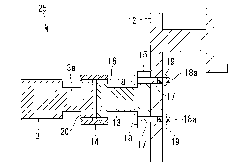
embodiment of the present invention will be described below
with reference to FIG. 1 to FIG. 3.
FIG. 1 is a longitudinal sectional view of the sun-and-
planet speed-up gear according to this embodiment. FIG. 2 is
a sectional view along the arrows B-B shown in FIG. 1. FIG. 3
is an enlarged main-portion view showing an enlarged main
portion shown in FIG. 1.
{0015}
A sun-and-planet speed-up gear 25 according to this
embodiment is used for a wind turbine (not shown), for
example. In FIG. 1, reference numeral 9 denotes an input
shaft, reference numeral 10 denotes an output shaft, and
reference numeral 11 denotes a power generator connected to
the output shaft 10. A low-speed-stage (first-stage) sun-and-
planet gearing (star-type sun-and-planet gearing) is provided
close to the input shaft 9, and a high-speed-stage (second-
stage) sun-and-planet gearing (planetary-type sun-and-planet
gearing) is provided close to the output shaft 10. Reference
CA 02731792 2011-04-15
8
numeral 1 denotes a low-speed-stage ring gear that is
connected to the input shaft 9 to rotate therewith, reference
numeral 2 denotes low-speed-stage planet gears that are
engaged with the low-speed-stage ring gear 1 and that rotate
about their fixed axes, and reference numeral 3 denotes a
low-speed-stage sun gear that is engaged with the low-speed-
stage planet gears 2 to rotate therewith.
{0016}
In FIG. 1 and FIG. 2, reference numeral 4 denotes a
fixed high-speed-stage ring gear, reference numeral 5 denotes
high-speed-stage planet gears that are engaged with the high-
speed-stage ring gear 4 to rotate therewith while their high-
speed-stage carrier 12 is connected to and revolves about a
shaft 3a of the low-speed-stage sun gear 3, and reference
numeral 6 denotes a high-speed-stage sun gear that is
rotationally driven by the high-speed-stage planet gears 5.
Note that the output shaft 10 is a rotary shaft of the
high-speed-stage sun gear 6 and rotates together therewith.
{0017}
In this sun-and-planet speed-up gear 25, the high-speed-
stage ring gear 4 is fixed; and the rotation of the input
shaft 9 is sequentially transferred to the low-speed-stage
ring gear 1, the low-speed-stage planet gears 2, the low-
speed-stage sun gear 3, the high-speed-stage planet gears 5,
and the high-speed-stage sun gear 6 to increase in speed; and
CA 02731792 2011-01-21
9
the rotation whose speed has been increased is output from the
output shaft 10.
100181
As shown in FIG. 3, in this embodiment, the shaft 3a of
the low-speed-stage sun gear 3 and the high-speed-stage
carrier 12 are coupled (connected) via a coupling 13 and a
sleeve 14.
The coupling 13 is a cylindrical-shaped member having an
I-shape in cross section that has a first flange 15 at one end
(end located close to the high-speed-stage carrier 12) and
that has a second flange 16 smaller in diameter than the first
flange 15 at the other end (end located close to the low-
speed-stage sun gear 3). In the first flange 15 and the high-
speed-stage carrier 12, a plurality of (for example, four)
through-holes 17 that pass therethrough in a plate-thickness
direction are formed in the circumferential direction, and
reamer bolts 18 pass through the through-holes 17. Then, the
coupling 13 is secured (attached) to the high-speed-stage
carrier 12 by means of the reamer bolts 18 that pass through
the through-holes 17 and nuts 19 that screw together male
screw parts 18a formed at the tips (ends located at the
opposite side of the bolt heads) of the reamer bolts 18, such
that an end face of the first flange 15 is brought into
contact with a surface of the high-speed-stage carrier 12.
{0019}
CA 02731792 2011-04-15
Note that, in this embodiment, the reamer bolts 18 and
the nuts 19 are fastened such that the heads of the reamer
bolts 18 protrude from the first flange 15, and the nuts 19
protrude from the high-speed-stage carrier 12.
Further, a flange 20 having the same diameter as the
second flange 16 is formed at the tip (end facing the
coupling 13) of the shaft 3a extending from the low-speed-
stage sun gear 3.
{0020}
The sleeve 14 is a hollow cylindrical-shaped member
having the same inner diameter as the outer diameters of the
second flange 16 and the flange 20 and is made from a rigid
material or a flexible material. Further, the sleeve 14 is
fitted radially outward, on the second flange 16 and the
flange 20 such that the inner circumference face thereof is
brought into contact with the outer circumference faces of
the second flange 16 and the flange 20.
{0021}
According to the sun-and-planet speed-up gear 25 of this
embodiment, the flange 20, which is formed at the tip of the
shaft 3a of the low-speed-stage sun gear 3, and the second
flange 16, which is formed at the other end of the coupling 13
directly attached to the high-speed-stage carrier 12 via the
reamer bolts 18 and the nuts 19, are coupled via the sleeve
14, so that the low-speed-stage sun gear 3 can move (somewhat:
CA 02731792 2011-01-21
11
slightly) in parallel in the radial direction.
Therefore, when the low-speed-stage sun gear 3 is
assembled, the low-speed-stage sun gear 3 is automatically
centered (the low-speed-stage sun gear 3 automatically moves
to a position where the distances between the center of the
low-speed-stage sun gear 3 and the centers of the low-speed-
stage planet gears 2 are equal), and thus damage to tooth
surfaces of the low-speed-stage sun gear 3 and the low-speed-
stage planet gears 2 and to a bearing (not shown) that
rotatably supports the input shaft 9 can be prevented.
{00221
A sun-and-planet speed-up gear according to a second
embodiment of the present invention will be described with
reference to FIG. 4. FIG. 4 is a sectional view of the sun-
and-planet speed-up gear according to this embodiment and is
an enlarged main-portion view showing an enlarged main portion
thereof.
As shown in FIG. 4, a sun-and-planet speed-up gear 30 of
this embodiment differs from that described above in the first
embodiment in that a coupling 31 is provided instead of the
coupling 13. Since the other components are the same as those
described above in the first embodiment, a description of the
components will be omitted here.
{00231
The coupling 31 is a cylindrical-shaped member having a
CA 02731792 2011-01-21
12
T-shape in cross section that has a flange 32 having the same
diameter as the flange 20 at one end (end located close to the
low-speed-stage sun gear 3) and is shorter in length in the
axial direction (longitudinal direction) than the coupling 13,
described in the first embodiment (approximately one third of
the coupling 13). Also, in the flange 32 and the high-speed-
stage carrier 12, a plurality of (for example, four) through-
holes 33 that pass therethrough in the plate-thickness
direction are formed in the circumferential direction, and the
reamer bolts 18 pass through the through-holes 33. Then, the
coupling 31 is secured (attached) to the high-speed-stage
carrier 12 by means of the reamer bolts 18 that pass through
the through-holes 33 and the nuts 19, which screw together the
male screw parts 18a formed at the tips (ends located at the
opposite side of the bolt heads) of the reamer bolts 18, such
that the other end face of the coupling 31 (end face facing a
surface of the high-speed-stage carrier 12) is brought into
contact with the surface of the high-speed-stage carrier 12.
{00241
On the other hand, a protrusion part 34 that protrudes
toward an end face of the shaft 3a and that has a length
(height) in the axial direction (longitudinal direction)
longer (higher) than the height (thickness) of the bolt heads
of the reamer bolts 18 is formed at the center of one end face
of the coupling 31.
CA 02731792 2011-04-15
13
This can prevent damage to the bolt heads caused when the
end faces (top faces) of the bolt heads are brought into
contact with the end face of the shaft 3a.
{0025}
Note that, in this embodiment, the reamer bolts 18 and
the nuts 19 are fastened such that the heads of the reamer
bolts 18 protrude from the flange 32, and the nuts 19
protrude from the high-speed-stage carrier 12.
Further, the sleeve 14 is fitted radially outward, on
the flange 20 and the flange 32 such that the inner
circumference face thereof is brought into contact with the
outer circumference faces of the flange 20 and the flange 32.
{0026}
According to the sun-and-planet speed-up gear 30 of this
embodiment, the flange 20, which is formed at the tip of the
shaft 3a of the low-speed-stage sun gear 3, and the flange
32, formed at one end of the coupling 31 directly attached to
the high-speed-stage carrier 12 via the reamer bolts 18 and
the nuts 19, are coupled via the sleeve 14, so that the low-
speed-stage sun gear 3 can move (somewhat: slightly) in
parallel in the radial direction.
Therefore, when the low-speed-stage sun gear 3 is
assembled, the low-speed-stage sun gear 3 is automatically
centered (the low-speed-stage sun gear 3 automatically moves
to a position where the distances between the center of the
CA 02731792 2011-01-21
14
low-speed-stage sun gear 3 and the centers of the low-speed-
stage planet gears 2 are equal), and thus damage to tooth
surfaces of the low-speed-stage sun gear 3 and the low-speed-
stage planet gears 2 and to a bearing (not shown) that
rotatably supports the input shaft 9 can be prevented.
{00271
Furthermore, according to the sun-and-planet speed-up
gear 30 of this embodiment, the coupling 31, which is shorter
in length in the axial direction than that of the first
embodiment, is used, thereby allowing a reduction in size in
the axial direction, making the gear more compact.
{00281
A sun-and-planet speed-up gear according to a third
embodiment of the present invention will be described with
reference to FIG. 5. FIG. 5 is a sectional view of the sun-
and-planet speed-up gear according to this embodiment and is
an enlarged main-portion view showing an enlarged main portion
thereof.
As shown in FIG. 5, a sun-and-planet speed-up gear 40 of
this embodiment differs from that described above in the first
embodiment in that a coupling 41 is provided instead of the
coupling 13 and the sleeve 14. Since the other components are
the same as those described above in the first embodiment, a
description of the components will be omitted here.
{0029}
CA 02731792 2011-01-21
The coupling 41 is a circular-disc-shaped member having
approximately the same diameter as a flange 42 that is formed
at the tip (end facing the coupling 41) of the shaft 3a,
extending from the low-speed-stage sun gear 3, is formed from
a flexible material, and is shorter in length in the axial
direction (longitudinal direction) than the coupling 13,
described in the first embodiment (approximately one third of
the coupling 13). Also, in the coupling 41 and the high-
speed-stage carrier 12, a plurality of (for example, two)
through-holes 43 that pass therethrough in the plate-thickness
direction are formed in the circumferential direction, and the
reamer bolts 18 pass through the through-holes 43. Then, the
coupling 41 is secured (attached) to the high-speed-stage
carrier 12 by means of the reamer bolts 18 that pass through
the through-holes 43 and the nuts 19, which screw together the
male screw parts 18a formed at the tips (ends located at the
opposite side of the bolt heads) of the reamer bolts 18, such
that part of one end face of the coupling 41 (end face facing
the surface of the high-speed-stage carrier 12) is brought
into contact with the surface of the high-speed-stage carrier
12. Further, in the coupling 41 and the flange 42, a
plurality of (for example, two) through-holes 44 that pass
therethrough in the plate-thickness direction are formed in
the circumferential direction, and the reamer bolts 18 pass
through the through-holes 44. Then, the coupling 41 is
=
CA 02731792 2011-01-21
16
secured (attached) to the flange 42 by means of the reamer
bolts 18 that pass through the through-holes 44 and the nuts
19, which screw together the male screw parts 18a formed at
the tips (ends located at the opposite side of the bolt heads)
of the reamer bolts 18, such that part of the other end face
of the coupling 41 (end face facing an end face of the flange
42) is brought into contact with the end face of the flange
42.
{00301
Note that, in this embodiment, the reamer bolts 18 and
the nuts 19 that couple the coupling 41 and the high-speed-
stage carrier 12 are fastened such that the heads of the
reamer bolts 18 protrude from the coupling 41, and the nuts 19
protrude from the high-speed-stage carrier 12. On the other
hand, the reamer bolts 18 and the nuts 19 that couple the
coupling 41 and the flange 42 are fastened such that the heads
of the reamer bolts 18 protrude from the coupling 41, and the
nuts 19 protrude from the flange 42.
{00311
According to the sun-and-planet speed-up gear 40 of this
embodiment, the low-speed-stage sun gear 3 and the high-speed-
stage carrier 12 are coupled via the flexible coupling 41 one
end of which is directly attached to the flange 42, formed at
the tip of the shaft 3a of the low-speed-stage sun gear 3, via
the reamer bolts 18 and the nuts 19, and the other end of
CA 02731792 2011-01-21
17
which is directly attached to the high-speed-stage carrier 12
via the reamer bolts 18 and the nuts 19, so that the low-
speed-stage sun gear 3 can move (somewhat: slightly) in
parallel in the radial direction.
Therefore, when the low-speed-stage sun gear 3 is
assembled, the low-speed-stage sun gear 3 is automatically
centered (the low-speed-stage sun gear 3 automatically moves
to a position where the distances between the center of the
low-speed-stage sun gear 3 and the centers of the low-speed-
stage planet gears 2 are equal), and thus damage to tooth
surfaces of the low-speed-stage sun gear 3 and the low-speed-
stage planet gears 2 and to a bearing (not shown) that
rotatably supports the input shaft 9 can be prevented.
{00321
Furthermore, according to the sun-and-planet speed-up
gear 40 of this embodiment, the coupling 41, which is shorter
in length in the axial direction than that of the first
embodiment, is used, thereby allowing a reduction in size in
the axial direction, making the gear more compact.
{0033}
Note that the present invention is not limited to the
above-described embodiments; and various changes and
modifications are allowed without departing from the gist of
the present invention.
For example, in the above-described embodiments, the
CA 02731792 2011-01-21
=
18
reamer bolts 18 and the nuts 19 are used as specific examples
of fastening means; however, instead of the reamer bolts 18
and the nuts 19, pins can be used to couple a coupling to the
high-speed-stage carrier 12 or the low-speed-stage sun gear 3.
In that case, it is just necessary to put the tips of the
pins into the high-speed-stage carrier 12 or the low-speed-
stage sun gear 3, thereby improving the assembly properties
(manufacturing properties).
{00341
Further, in the above-described embodiments, descriptions
have been given of the specific example cases in which the
coupling 13 or 31 is coupled to the high-speed-stage carrier
12 via the reamer bolts 18 and the nuts 19; however, the
coupling 13 or 31 and the high-speed-stage carrier 12 may be
formed as a unit.
{Reference Signs List)
100351
1 low-speed-stage ring gear
2 low-speed-stage planet gears
3 low-speed-stage sun gear
3a shaft
6 high-speed-stage sun gear
9 input shaft
output shaft
12 high-speed-stage carrier
CA 02731792 2011-01-21
19
13 coupling
14 sleeve
16 second flange (flange)
20 flange
25 sun-and-planet speed-up gear
30 sun-and-planet speed-up gear
31 coupling
32 flange
40 sun-and-planet speed-up gear
41 coupling
42 flange