Note: Descriptions are shown in the official language in which they were submitted.
CA 02731987 2011-01-25
WO 2010/091133 PCT/US2010/023127
SYRINGE WITH VISUAL USE INDICATOR
RELATED APPLICATIONS
This application claims priority to US Provisional Patent Application No,
61/149,720 filed on 4 February
2009 entitled "SYRINGE WITH VISUAL USE INDICATOR".
FIELD OF THE INVENTION
The present invention generally relates to the field of syringes and, more
particularly, to providing
information that fluid may have previously been discharged from a syringe.
BACKGROUND
Various medical procedures require that one or more medical fluids be injected
into a patient. For
example, medical imaging procedures oftentimes involve the injection of
contrast media into a patient, possibly
along with saline or other fluids. Other medical procedures involve injecting
one or more fluids into a patient for
therapeutic purposes. Power injectors may be used for these types of
applications.
A power injector generally includes what is commonly referred to as a
powerhead. One or more syringes
may be mounted to the powerhead in various manners (e.g., detachably; rear-
loading; front-loading; side-loading).
Each syringe typically includes what may be characterized as a syringe
plunger, piston, or the like. Each such
syringe plunger is designed to interface with (e.g., contact and/or
temporarily interconnect with) an appropriate
syringe driver that is incorporated into the powerhead, such that operation of
the syringe driver axially advances
the associated syringe plunger inside and relative to a barrel of the syringe.
One typical syringe driver is in the
form of a ram that is mounted on a threaded lead or drive screw. Rotation of
the drive screw in one rotational
direction advances the associated ram in one axial direction, while rotation
of the drive screw in the opposite
rotational direction advances the associated ram in the opposite axial
direction.
Power injector syringes may be disposable - only used for a single injection.
If a power injector syringe
were to be re-used, it should be sterilized before being reloaded with fluid
for use in a subsequent injection.
SUMMARY
As used herein, the phrase "fluidly isolated" or the like describes a
relationship between components
where fluid is not able to flow between the components. For example, where two
components are fluidly isolated
from each other, fluid is currently unable to flow from one component to the
other component. Such an inability to
flow may be due to one or more valves being positioned to prevent such flow
between the two components.
Certain components may at all times be fluidly isolated from each other.
As used herein, the phrases "fluidly interconnected, "in fluid communication
with," "fluidly communicates
with," or the like each describes a relationship between components where
fluid is currently able to flow between
the components. Such an inability to flow may be due to one or more valves
being positioned to allow such flow
1
CA 02731987 2011-01-25
WO 2010/091133 PCT/US2010/023127
between the two components. Certain components may at all times be in fluid
communication with each other.
For example, "an injection device fluidly interconnected to a patient"
describes a configuration where fluid is able to
flow from the injection device, through any intermediate components (e.g.,
tubing, connectors), and to the patient
(e.g., into the vasculature of the patient).
A first aspect of the present invention is embodied by a power injector that
includes a syringe plunger
driver and a syringe. The syringe plunger driver includes a plunger interface
and a motorized drive source
operable to move the plunger interf ace in multiple directions (e.g., in each
direction along an axial path). The
syringe includes an internal fluid discharge chamber, a syringe plunger that
is movably disposed within this fluid
discharge chamber, and a visual indicator member that is located outside of
the fluid discharge chamber (e.g., on
an exterior surface of the syringe). To discharge the syringe, the syringe
plunger driver interacts with the syringe
plunger to move the syringe plunger in at least a first direction. Prior to
the advancement of the syringe plunger,
the visual indicator member is in a first state, but the visual indicator
member is irreversibly changed to a second
state in response to the movement of the syringe plunger by the syringe
plunger driver,
A number of feature refinements and additional features are applicable to the
first aspect of the present
invention. These feature refinements and additional features may be used
individually or in any combination. The
following discussion is applicable to the first aspect, up to the start of the
discussion of a second aspect of the
present invention.
The syringe may include a syringe body, where the syringe plunger is movable
relative to the syringe
body and where at least part of the syringe plunger (e.g., a plunger head) is
disposed within the syringe body. To
move the syringe plunger within the syringe body in at least a first axial
direction, the syringe plunger driver may
include an axially moveable ram, and the plunger interface may move along with
the ram. In turn, the plunger
interface interacts with the syringe plunger to move it in at least one axial
direction. The plunger interface may be
of any appropriate size, shape, configuration, and/or type to allow the
syringe plunger driver to interact with the
syringe plunger in any appropriate manner to move the syringe plunger in at
least one axial direction (e.g., a
mechanical coupling, magnetic coupling, etc.).
The visual indicator member may be disposed on an exterior of the syringe body
such that the visual
indicator member remains at all times isolated from any fluid contained within
the syringe (e.g., fluid within the fluid
discharge chamber). For instance, the visual indicator member may be disposed
between the syringe body and a
label attached to an exterior of the syringe body. To allow an operator to
observe the visual indicator member, the
label may include at least one transparent section that coincides with the
visual indicator member such that the
visual indicator member is visible through the transparent section. The
transparent section may be a discrete
portion of the label or it may coincide with the entirety of the label, and
the transparent section may be formed of
any material that accommodates viewing a visual change through the transparent
section. For example, the
transparent section may be clear or of translucent color so long as an
operator may perceive a visual change
through the transparent section.
The visual indicator member itself may be in the form of a pressure-sensitive
material. This pressure-
sensitive material may include any material that exhibits an optically
detectable response to changes in pressure
2
CA 02731987 2011-01-25
WO 2010/091133 PCT/US2010/023127
(e.g., a pressure-sensitive adhesive, polymer, gel, foam, etc.). For example,
the pressure-sensitive material may
take the form of a label adhesive, a separate material that is disposed
between a label and the syringe body, or it
may be incorporated into the label itself. When disposed outside of the fluid
discharge chamber (e.g., on an
exterior of the syringe body), the pressure-sensitive material may change from
a first color to a second color in
response to exposure to a pressure change. Thus, as the syringe plunger
advances in a direction to discharge
fluid from the syringe, the pressure within the syringe body increases,
thereby causing the pressure-sensitive
material to change from a first state (e.g., a first color) to a second state
(e,g., a second color),
The visual indicator member could also be in the form of a fluid source. The
fluid source may include a
first fluid within an enclosure. The first fluid may be any visible indicator
fluid (e.g., a colored fluid, for instance a
liquid) of an appropriate viscosity that allows the indicator fluid to flow,
and the enclosure may be formed of any
deformable, malleable, and/or rupturable material that ruptures upon exposure
to at least a certain pressure (e.g.,
a blister pack).
The visual indicator member may further include a flowpath that is
interconnectable with the fluid source.
The flowpath may be configured such that the first fluid and the flowpath are
fluidly isolated when the visual
indicator member is in a first state (i.e., before the fluid source ruptures),
but that the first fluid flows within the
flowpath when the visual indicator member is in a second state (i.e., after
the fluid source ruptures). The flowpath
may be a channel that is inset into or fully enclosed within the exterior of
the syringe and that recedes from the fluid
source. The channel may be of any appropriate size, shape, and/or
configuration to allow fluid to flow within it
along a visible portion of the syringe body (e.g., at least about 10% of a
length of the syringe body). In addition, a
label may be disposed over the flowpath (such that the first fluid is
contained between the label and an exterior of
the syringe). To allow an operator to observe the visual indicator member, the
label may include at least one
transparent section that coincides with the visual indicator member such that
the visual indicator member is visible
through the transparent section. The transparent section may be a discrete
portion of the label or it may coincide
with the entirety of the label, and the transparent section may be formed of
any material that accommodates
viewing a visual change through the transparent section. For example, the
transparent section may be clear or of
translucent color so long as an operator may perceive a visual change through
the transparent section.
In one embodiment, the fluid source may be aligned with a moveable member.
This movable member
may be incorporated into the structure of the syringe. For instance, the
moveable member may be a dimple, a
hollow, or a depression in the surface of the syringe that may be of any
appropriate size, shape, and/or
configuration to receive the fluid source. In a first position, the moveable
member may be convex in relation to the
interior of the syringe and concave in relation to the exterior of the
syringe. In a second position, the moveable
member may be convex in relation to the exterior of the syringe and concave in
relation to the interior of the
syringe. The moveable member may move between the first and second positions,
or invert, in response to a
pressure increase in the interior of the syringe that develops within the
syringe as the syringe plunger advances in
a direction to discharge fluid from the syringe. This inversion, or movement
between the first and second
positions, may compress the fluid source between the moveable member and
another structure (e.g., an overlying
3
CA 02731987 2011-01-25
WO 2010/091133 PCT/US2010/023127
label), thereby causing the fluid source to rupture and release the indicator
fluid to flow down the flowpath and
serve as a visual indicator that the power injector has discharged fluid from
the syringe.
In one embodiment, the syringe may be disposed within a pressure jacket that
is configured to restrain
the syringe body when the syringe is pressurized. The pressure jacket may be
of any appropriate size, shape,
configuration, and/or type to fully encompass the syringe body and withstand a
certain amount of outward force
from the pressurized syringe so as to prevent the pressurized syringe from
rupturing when fully pressurized by the
power injector. In this embodiment, the moveable member may be a deformable,
frustu mly-sh aped section of the
syringe located between a syringe barrel and a discharge port of the syringe
body. The fluid source may be
disposed upon the frustumly-shaped surface between the exterior surface of the
syringe and a corresponding
interior surface of the pressure jacket. As the syringe plunger driver
advances the syringe plunger in a direction to
discharge fluid from the syringe, the moveable member may deform and/or the
syringe may move axially relative to
the pressure jacket in response to a pressure increase that develops within
the syringe. This deformation and/or
syringe movement may compress the fluid source between the exterior surface of
the syringe and the interior
surface of the pressure jacket, which may rupture the fluid source and release
the indicator fluid to flow along the
flow path.
A second aspect of the present invention is embodied by a power injector that
includes a syringe plunger
driver, a light source, and a syringe. The syringe plunger driver includes a
plunger interface and a motorized drive
source that is operable to move the plunger interface in multiple directions
(e.g., in each direction along an axial
path). The syringe includes a syringe plunger and a visual indicator member
that irreversibly changes between a
first state and a second state in response to the activation of the light
source.
A third aspect of the present invention is embodied by a method of operation
for a power injector. This
method includes the steps of exposing a visual indicator member on a syringe
to an output from a light source in
order to change the color of the visual indicator, and advancing a ram to in
turn advance a syringe plunger.
A number of feature refinements and additional features are applicable to the
second and third aspects of
the present invention. These feature refinements and additional features may
be used individually or in any
combination. The following discussion is applicable to the second and third
aspects, up to the start of the
discussion of a fourth aspect of the present invention.
The light source may be of any appropriate type, and may issue light of any
appropriate wavelength or
combination of wavelengths (e.g., ultra violet ("UV") light). Operation of the
light source could be controlled by the
power injector, the light source could be manually activated (e.g., by a
clinician), or both. The light source may be
incorporated by the power injector in any appropriate manner. For instance,
the power injector may include a
powerhead of any appropriate size, shape, configuration, and/or type, and the
light source could be integrated into
the structure of the powerhead. The light source could also be detachably
mounted to the power injector in any
appropriate manner and at any appropriate location, In one embodiment, the
light source is a handheld unit and
may be manually operated.
The visual indicator member may be disposed on an exterior of the syringe such
that the visual indicator
member remains at all times fluidly isolated from any fluid contained within
the syringe. For instance, the visual
4
CA 02731987 2011-01-25
WO 2010/091133 PCT/US2010/023127
indicator member may be disposed between the syringe body and a label. To
allow an operator to observe the
visual indicator member, the label may include at least one transparent
section that coincides with the visual
indicator member such that the visual indicator member is visible through the
transparent section. The transparent
section may be a discrete portion of the label or it may coincide with the
entirety of the label, and the transparent
section may be formed of any material that accommodates viewing a visual
change through the transparent
section. For instance, the transparent section may be clear or have a
translucent color that allows an operator
may perceive a visual change through the transparent section.
The visual indicator member itself may be formed of any appropriate light-
sensitive material that exhibits
an optically detectable response to exposure to at least certain light (e.g.,
UV-sensitive adhesives, gels, foams,
paints, etc.). For example, the light-sensitive material may take the form of
a label adhesive, a separate material
that is disposed beneath the label, or it may be incorporated into the
structure of the label itself. When disposed
on the exterior of the syringe body, the visual indicator member may change
from a first color to a second color
upon exposure to at least a certain light, thereby providing a visual
indication to an operator that the power injector
has discharged fluid from the syringe.
The light exposure may occur either before or after advancement of the syringe
plunger to discharge fluid
from the syringe. In addition, an operator may manually initiate exposure or
exposure may be integrated with an
injection or operations protocol such that exposure occurs automatically at
the appropriate time.
A fourth aspect of the present invention is embodied by a syringe. Components
of the syringe include a
syringe body having an interior surface and an exterior surface, a syringe
plunger moveably disposed within the
syringe body, a label disposed on the exterior surface of the syringe body,
and a pressure-sensitive material
disposed between the label and the exterior surface of the syringe body,
A number of feature refinements and additional features are applicable to the
fourth aspect of the present
invention. These feature refinements and additional features may be used
individually or in any combination. The
following discussion is applicable to the fourth aspect, up to the start of
the discussion of a fifth aspect of the
present invention.
The syringe plunger may have a proximal end that includes a coupling adapted
to interact with a syringe
plunger driver of a power injector. The power injector may be any appropriate
power injector adapted for use with
a syringe, and the coupling may be of any appropriate size, shape,
configuration, and/or type to allow the syringe
plunger driver to interact with the syringe plunger to move the syringe
plunger in at least one direction.
To allow an operator to observe the pressure-sensitive material, the label may
be disposed on the exterior
surface of the syringe body, and furthermore may include at least one
transparent section that coincides with the
pressure-sensitive material such that the material is visible through the
transparent section. The transparent
section may be a discrete portion of the label or it may coincide with the
entirety of the label, and the transparent
section may be formed of any material that accommodates viewing a visual
change through the transparent
section. For instance, the transparent section may be clear or of translucent
color so long as an operator may
perceive a visual change through the transparent section.
5
CA 02731987 2011-01-25
WO 2010/091133 PCT/US2010/023127
The pressure-sensitive material itself may be any material that exhibits an
optically detectable response
to changes in pressure (e.g., a pressure-sensitive adhesive, polymer, gel,
foam, etc.). For example, the pressure-
sensitive material may take the form of a label adhesive or of another,
separate material that is disposed beneath
the label. When disposed between the label and the exterior surface of the
syringe body, the pressure-sensitive
material may change from a first color to a second color in response to a
pressure change. That is, prior to
exposure to at least a first pressure, the pressure-sensitive material is in a
first sate (e.g., a first color), and after
exposure to at least a first pressure, the pressure-sensitive material is
irreversibly changed to a second state (e.g.,
a second color).
A fifth aspect of the present invention is embodied by a syringe having a
syringe body, which in turn
includes an internal fluid discharge chamber. The syringe further includes a
syringe plunger that movably
disposed within the syringe body (e.g., within the fluid discharge chamber), a
fluid source that is disposed outside
of the fluid discharge chamber, and a movable member aligned with the fluid
source.
A sixth aspect of the present invention is embodied by a method for operating
a power injector. The
method includes the steps of advancing a ram to advance a syringe plunger of a
syringe, expanding a first portion
of the syringe in response to a differential pressure created in the syringe
as the syringe plunger advances, and
activating a first visual indicator in response to this expansion of the
syringe.
A number of feature refinements and additional features are applicable to the
fifth and sixth aspects of the
present invention. These feature refinements and additional features may be
used individually or in any
combination.
The first visual indicator may be a fluid source that includes a first fluid
within an enclosure. The first fluid
may be any visible indicator fluid (e.g., a colored liquid, etc.) of an
appropriate viscosity that allows the indicator
fluid to flow, and the enclosure may be formed of a deforrnable, malleable,
and/or rupturable material that ruptures
upon exposure to at least a certain pressure (e.g., a blister pack).
In addition, the syringe may include a flowpath that is fluidly
interconnectable with the fluid source. The
flowpath may be a channel that is inset into or fully enclosed on an exterior
of the syringe body (e.g., so as to be
fluidly isolated from an internal fluid discharge chamber of the syringe) and
that extends from the fluid source down
a visible portion of the syringe body (e.g., to at least about 10% down the
length of the syringe body). Ina first
state (i.e., prior to an advancement of the syringe plunger to discharge fluid
from the syringe body), the fluid source
and the flowpath may be fluidly isolated, while in a second state (i.e., the
development of a differential pressure in
response to the advancement of the syringe plunger), the fluid source
communicates with the flowpath. A label
may be disposed over each of the fluid source and the channel. The label may
include a transparent section that
coincides with at least a portion of the channel. The transparent section may
be a discrete portion of the label or it
may coincide with the entirety of the label, and the transparent section may
be formed of any material that
accommodates viewing a visual change through the transparent section. For
instance, the transparent section
may be clear or of translucent color so long as an operator may perceive a
visual change through the transparent
section.
6
CA 02731987 2011-01-25
WO 2010/091133 PCT/US2010/023127
In one embodiment, the moveable member may be a dimple, a hollow, or a
depression formed in the
structure of the syringe. The moveable member may be of any appropriate size,
shape, and/or configuration so as
to receive the fluid source. In a first position and prior to the movement of
the syringe plunger to discharge fluid
from the syringe, the moveable member may be convex relative to the interior
of the syringe and concave relative
to the exterior of the syringe. As the syringe plunger advances to discharge
fluid from the syringe body, a
differential pressure develops. In response to this differential pressure, the
moveable member may move from the
first position to a second position (e.g., invert) such that the moveable
member is now concave relative to the
interior of the syringe and convex relative to the exterior of the syringe.
The inversion, or movement of the
moveable member between the first and second positions, may compress the fluid
source between the moveable
member and another structure (e.g., a label on an exterior of the syringe),
thereby rupturing the fluid source and
releasing the first fluid to flow along the flowpath where an operator may
view the resulting color change through
the transparent section of the label and know that fluid has been discharged
fluid from the syringe.
In one embodiment, the syringe may be disposed within a pressure jacket that
is configured to restrain
the syringe body when the syringe is pressurized. The pressure jacket may be
of any appropriate size, shape,
5 configuration, and/or type to fully encompass the syringe body and withstand
a certain amount of outward force
from the pressurized syringe so as to prevent the pressurized syringe from
rupturing when fully pressurized. In this
embodiment, the moveable member may be a deformable, frustumly-shaped section
of the syringe located
between a syringe barrel and a discharge port of the syringe body. The fluid
source may coincide with the
frustumly-shaped surface between the exterior surface of the syringe body and
the pressure jacket.
As the syringe plunger advances to discharge fluid from the syringe body, the
deformable section may
distort outward and/or the syringe may move axially relative to the pressure
jacket to compress the fluid source
between the exterior surface of the syringe and an interior surface of the
pressure jacket. As a result, the fluid
source ruptures, and the indicator fluid flows down the flowpath where it is
visible to an operator through the
transparent portion of the label, thereby providing a visual indication that
the power injector has discharged fluid
from the syringe.
A number of feature refinements and additional features are separately
applicable to each of above-noted
first, second, third, fourth, fifth, and sixth aspects of the present
invention. These feature refinements and
additional features may be used individually or in any combination in relation
to each of the above-noted first,
second, third, fourth, fifth, and sixth aspects. Any feature of any other
various aspects of the present invention that
is intended to be limited to a "singular" context or the like will be clearly
set forth herein by terms such as "only,"
"single," "limited to," or the like. Merely introducing a feature in
accordance with commonly accepted antecedent
basis practice does not limit the corresponding feature to the singular (e.g.,
indicating that a power injector includes
"a syringe" alone does not mean that the power injector includes only a single
syringe). Moreover, any failure to
use phrases such as "at least one" also does not limit the corresponding
feature to the singular (e.g., indicating
that a power injector includes "a syringe" alone does not mean that the power
injector includes only a single
syringe). Finally, use of the phrase "at least generally" or the like in
relation to a particular feature encompasses
7
CA 02731987 2011-01-25
WO 2010/091133 PCT/US2010/023127
the corresponding characteristic and insubstantial variations thereof (e,g.,
indicating that a syringe barrel is at least
generally cylindrical encompasses the syringe barrel being cylindrical).
Any power injector that may be utilized to provide a fluid discharge may be of
any appropriate size,
shape, configuration, and/or type. Any such power injector may utilize one or
more syringe plunger drivers of any
appropriate size, shape, configuration, and/or type, where each such syringe
plunger driver is capable of at least
bi-directional movement (e.g., a movement in a first direction for discharging
fluid; a movement in a second
direction for accommodating a loading of fluid or so as to return to a
position for a subsequent fluid discharge
operation), and where each such syringe plunger driver may interact with its
corresponding syringe plunger in any
appropriate manner (e.g,, by mechanical contact; by an appropriate coupling
(mechanical or otherwise)) so as to
be able to advance the syringe plunger in at least one direction (e.g., to
discharge fluid). Each syringe plunger
driver may utilize one or more drive sources of any appropriate size, shape,
configuration, and/or type. Multiple
drive source outputs may be combined in any appropriate manner to advance a
single syringe plunger at a given
time. One or more drive sources may be dedicated to a single syringe plunger
driver, one or more drive sources
may be associated with multiple syringe plunger drivers (e.g., incorporating a
transmission of sorts to change the
output from one syringe plunger to another syringe plunger), or a combination
thereof. Representative drive
source forms include a brushed or brushless electric motor, a hydraulic motor,
a pneumatic motor, a piezoelectric
motor, or a stepper motor.
Any such power injector may be used for any appropriate application where the
delivery of one or more
medical fluids is desired, including without limitation any appropriate
medical application (e.g., computed
tomography or CT imaging; magnetic resonance imaging or MRI; single photon
emission computed tomography or
SPECT imaging; positron emission tomography or PET imaging; X-ray imaging;
angiographic imaging; optical
imaging; ultrasound imaging). Any such power injector may be used in
conjunction with any component or
combination of components, such as an appropriate imaging system (e.g., a CT
scanner). For instance,
information could be conveyed between any such power injector and one or more
other components (e.g., scan
delay information, injection start signal, injection rate).
Any appropriate number of syringes may be utilized with any such power
injector in any appropriate
manner (e.g., detachably; front-loaded; rear-loaded; side-loaded), any
appropriate medical fluid may be discharged
from a given syringe of any such power injector (e.g., contrast media, a
radiopharmaceutical, saline, and any
combination thereof), and any appropriate fluid may be discharged from a
multiple syringe power injector
configuration in any appropriate manner (e.g., sequentially, simultaneously),
or any combination thereof. In one
embodiment, fluid discharged from a syringe by operation of the power injector
is directed into a conduit (e.g.,
medical tubing set), where this conduit is fluidly interconnected with the
syringe in any appropriate manner and
directs fluid to a desired location (e.g., to a catheter that is inserted into
a patient, for instance for injection).
Multiple syringes may discharge into a common conduit (e.g., for provision to
a single injection site), or one syringe
may discharge into one conduit (e.g., for provision to one injection site),
while another syringe may discharge into a
different conduit (e.g., for provision to a different injection site). In one
embodiment, each syringe includes a
syringe barrel and a plunger that is disposed within and movable relative to
the syringe barrel. This plunger may
8
CA 02731987 2011-01-25
WO 2010/091133 PCT/US2010/023127
interface with the power injector's syringe plunger drive assembly such that
the syringe plunger drive assembly is
able to advance the plunger in at least one direction, and possibly in two
different, opposite directions.
The syringes disclosed herein may be used with power injectors as noted.
However, these syringes may
be used with other types of injection devices. For instance, these syringes
may be used with a hand-held, hand-
powered syringe having a pair of levers that are movably interconnected (e.g.,
by a pivot pin), where one lever is
also movably interconnected with the syringe body (e.g., by a pivot pin), and
where the other lever is movably
interconnected with the plunger (e.g., by a pivot pin) such that that a single
hand of a user may engage and
manipulate the levers to change the position of the plunger relative to the
syringe body. Although any appropriate
pressure could trigger the visual indication discussed herein, in one
embodiment the trigger pressure is of a more
elevated level such that these syringes may be suited for fluid delivery
devices that are capable of generating
elevated pressures.
BRIEF DESCRIPTION OF THE FIGURES
Figure 1 is a schematic of one embodiment of a power injector.
Figure 2A is a perspective view of one embodiment of a portable stand-mounted,
dual-head power
injector.
Figure 2B is an enlarged, partially exploded, perspective view of a powerhead
used by the power injector
of Figure 2A.
Figure 2C is a schematic of one embodiment of a syringe plunger drive assembly
used by the power
injector of Figure 2A.
Figure 3 is a perspective view of a syringe that utilizes one embodiment of a
visual indicator.
Figure 4A is an exploded perspective view of the syringe of Figure 3.
Figure 4B is a cross-sectional view of the syringe of Figure 3.
Figure 5A is a perspective view of a syringe that utilizes another embodiment
of a visual indicator.
Figure 5B is an exploded perspective view of the syringe of Figure 5A.
Figure 5C is a partial, enlarged, cross-sectional view of the syringe of
Figure 5A in a first state.
Figure 5D is a detailed view of the fluid source.
Figure 5E is a partial, enlarged, cross-sectional view of the syringe of
Figure 5A in a second state.
Figure 6A is a perspective view of a syringe that utilizes another embodiment
of a visual indicator, and
that is used in conjunction with a pressure jacket on a power injector.
Figure 6B is an exploded perspective view of the syringe of Figure 6A.
Figure 6C is a partial, enlarged, cross-sectional view of the syringe of
Figure 6A in a first state.
Figure 6D is a detailed view of a portion of the syringe of Figure 6C.
Figure 6E is a partial, enlarged, cross-sectional view of the syringe of
Figure 6A in a second state.
Figure 7 is a schematic of a syringe for a power injector that utilizes
another embodiment of a visual
indicator.
9
CA 02731987 2011-01-25
WO 2010/091133 PCT/US2010/023127
DETAILED DESCRIPTION
Figure 1 presents a schematic of one embodiment of a power injector 10 having
a powerhead 12. One or
more graphical user interfaces or GUIs 11 may be associated with the powerhead
12. Each GUI 11: 1) may be of
any appropriate size, shape, configuration, and/or type; 2) may be operatively
interconnected with the powerhead
12 in any appropriate manner; 3) may be disposed at any appropriate location;
4) may be configured to provide
one or any combination of the following functions: controlling one or more
aspects of the operation of the power
injector 10; inputting/editing one or more parameters associated with the
operation of the power injector 10; and
displaying appropriate information (e.g., associated with the operation of the
power injector 10); or 5) any
combination of the foregoing. Any appropriate number of GUIs 11 may be
utilized, In one embodiment, the power
injector 10 includes a GUI 11 that is incorporated by a console that is
separate from but which communicates with
the powerhead 12. In another embodiment, the power injector 10 includes a GUI
11 that is part of the powerhead
12. In yet another embodiment, the power injector 10 utilizes one GUI 11 on a
separate console that
communicates with the powerhead 12, and also utilizes another GUI 11 that is
on the powerhead 12. Each GUI 11
could provide the same functionality or set of functionalities, or the GUIs 11
may differ in at least some respect in
relation to their respective functionalities.
A syringe 28 may be installed on this powerhead 12 and, when installed, may be
considered to be part of
the power injector 10. Some injection procedures may result in a relatively
high pressure being generated within
the syringe 28. In this regard, it may be desirable to dispose the syringe 28
within a pressure jacket 26. The
pressure jacket 26 is typically associated with the powerhead 12 in a manner
that allows the syringe 28 to be
disposed therein as a part of or after installing the syringe 28 on the
powerhead 12. The same pressure jacket 26
will typically remain associated with the powerhead 12, as various syringes 28
are positioned within and removed
from the pressure jacket 26 for multiple injection procedures. The power
injector 10 may eliminate the pressure
jacket 26 if the power injector 10 is configured/utilized for low-pressure
injections and/or if the syringe(s) 28 to be
utilized with the power injector 10 is (are) of sufficient durability to
withstand high-pressure injections without the
additional support provided by a pressure jacket 26. In any case, fluid
discharged from the syringe 28 may be
directed into a conduit 38 of any appropriate size, shape, configuration,
and/or type, which may be fluidly
interconnected with the syringe 28 in any appropriate manner, and which may
direct fluid to any appropriate
location (e.g., to a patient).
The powerhead 12 includes a syringe plunger drive assembly or syringe plunger
driver 14 that interacts
(e.g., interfaces) with the syringe 28 (e.g., a plunger 32 thereof) to
discharge fluid from the syringe 28. This
syringe plunger drive assembly 14 includes a drive source 16 (e.g., a motor of
any appropriate size, shape,
configuration, and/or type, optional gearing, and the like) that powers a
drive output 18 (e.g., a rotatable drive
screw). A ram 20 may be advanced along an appropriate path (e.g., axial) by
the drive output 18. The ram 20
may include a coupler 22 for interacting or interfacing with a corresponding
portion of the syringe 28 in a manner
that will be discussed below.
The syringe 28 includes a plunger or piston 32 that is movably disposed within
a syringe barrel 30 (e.g.,
for axial reciprocation along an axis coinciding with the double-headed arrow
B). The plunger 32 may include a
CA 02731987 2011-01-25
WO 2010/091133 PCT/US2010/023127
coupler 34. This syringe plunger coupler 34 may interact or interface with the
ram coupler 22 to allow the syringe
plunger drive assembly 14 to retract the syringe plunger 32 within the syringe
barrel 30. The syringe plunger
coupler 34 may be in the form of a shaft 36a that extends from a body of the
syringe plunger 32, together with a
head or button 36b. However, the syringe plunger coupler 34 may be of any
appropriate size, shape,
configuration, and/or type.
Generally, the syringe plunger drive assembly 14 of the power injector 10 may
interact with the syringe
plunger 32 of the syringe 28 in any appropriate manner (e.g., by mechanical
contact; by an appropriate coupling
(mechanical or otherwise)) so as to be able to move or advance the syringe
plunger 32 (relative to the syringe
barrel 30) in at least one direction (e.g., to discharge fluid from the
corresponding syringe 28). That is, although
the syringe plunger drive assembly 14 may be capable of bi-directional motion
(e.g., via operation of the same
drive source 16), the power injector 10 may be configured such that the
operation of the syringe plunger drive
assembly 14 actually only moves each syringe plunger 32 being used by the
power injector 10 in only one
direction. However, the syringe plunger drive assembly 14 may be configured to
interact with each syringe plunger
32 being used by the power injector 10 so as to be able to move each such
syringe plunger 32 in each of two
different directions (e.g. in different directions along a common axial path).
Retraction of the syringe plunger 32 may be utilized to accommodate a loading
of fluid into the syringe
barrel 30 for a subsequent injection or discharge, may be utilized to actually
draw fluid into the syringe barrel 30 for
a subsequent injection or discharge, or for any other appropriate purpose.
Certain configurations may not require
that the syringe plunger drive assembly 14 be able to retract the syringe
plunger 32, in which case the ram coupler
22 and syringe plunger coupler 34 may not be desired. In this case, the
syringe plunger drive assembly 14 may be
retracted for purposes of executing another fluid delivery operation (e.g.,
after another pre-filled syringe 28 has
been installed). Even when a ram coupler 22 and syringe plunger coupler 34 are
utilized, it may such that these
components may or may not be coupled when the ram 20 advances the syringe
plunger 32 to discharge fluid from
the syringe 28 (e.g., the ram 20 may simply "push on" the syringe plunger
coupler 34 or directly on a proximal end
of the syringe plunger 32). Any single motion or combination of motions in any
appropriate dimension or
combination of dimensions may be utilized to dispose the ram coupler 22 and
syringe plunger coupler 34 in a
coupled state or condition, to dispose the ram coupler 22 and syringe plunger
coupler 34 in an un-coupled state or
condition, or both.
The syringe 28 may be installed on the powerhead 12 in any appropriate manner.
For instance, the
syringe 28 could be configured to be installed directly on the powerhead 12.
In the illustrated embodiment, a
housing 24 is appropriately mounted on the powerhead 12 to provide an
interface between the syringe 28 and the
powerhead 12. This housing 24 may be in the form of an adapter to which one or
more configurations of syringes
28 may be installed, and where at least one configuration for a syringe 28
could be installed directly on the
powerhead 12 without using any such adapter. The housing 24 may also be in the
form of a faceplate to which
one or more configurations of syringes 28 may be installed. In this case, it
may be such that a faceplate is
required to install a syringe 28 on the powerhead 12 - the syringe 28 could
not be installed on the powerhead 12
without the faceplate. When a pressure jacket 26 is being used, it may be
installed on the powerhead 12 in the
11
CA 02731987 2011-01-25
WO 2010/091133 PCT/US2010/023127
various manners discussed herein in relation to the syringe 28, and the
syringe 28 will then thereafter be installed
in the pressure jacket 26.
The housing 24 may be mounted on and remain in a fixed position relative to
the powerhead 12 when
installing a syringe 28. Another option is to movably interconnect the housing
24 and the powerhead 12 to
accommodate installing a syringe 28. For instance, the housing 24 may move
within a plane that contains the
double-headed arrow A to provide one or more of coupled state or condition and
an un-coupled state or condition
between the ram coupler 22 and the syringe plunger coupler 34.
One particular power injector configuration is illustrated in Figure 2A, is
identified by a reference numeral
40, and is at least generally in accordance with the power injector 10 of
Figure 1. The power injector 40 includes a
powerhead 50 that is mounted on a portable stand 48. A pair of syringes 86a,
86b for the power injector 40 is
mounted on the powerhead 50. Fluid may be discharged from the syringes 86a,
86b during operation of the power
injector 40.
The portable stand 48 may be of any appropriate size, shape, configuration,
and/or type. Wheels, rollers,
casters, or the like may be utilized to make the stand 48 portable. The
powerhead 50 could be maintained in a
fixed position relative to the portable stand 48. However, it may be desirable
to allow the position of the
powerhead 50 to be adjustable relative to the portable stand 48 in at least
some manner. For instance, it may be
desirable to have the powerhead 50 in one position relative to the portable
stand 48 when loading fluid into one or
more of the syringes 86a, 86b, and to have the powerhead 50 in a different
position relative to the portable stand
48 for performance of an injection procedure. In this regard, the powerhead 50
may be movably interconnected
with the portable stand 48 in any appropriate manner (e.g., such that the
powerhead 50 may be pivoted through at
least a certain range of motion, and thereafter maintained in the desired
position).
It should be appreciated that the powerhead 50 could be supported in any
appropriate manner for
providing fluid. For instance, instead of being mounted on a portable
structure, the powerhead 50 could be
interconnected with a support assembly, that in turn is mounted to an
appropriate structure (e.g., ceiling, wall,
floor). Any support assembly for the powerhead 50 may be positionally
adjustable in at least some respect (e.g.,
by having one or more support sections that may be repositioned relative to
one more other support sections), or
may be maintained in a fixed position. Moreover, the powerhead 50 may be
integrated with any such support
assembly so as to either be maintained in a fixed position or so as to be
adjustable relative the support assembly.
The powerhead 50 includes a graphical user interface or GUI 52. This GUI 52
may be configured to
provide one or any combination of the following functions: controlling one or
more aspects of the operation of the
power injector 40; inputting/editing one or more parameters associated with
the operation of the power injector 40;
and displaying appropriate information (e.g., associated with the operation of
the power injector 40). The power
injector 40 may also include a console 42 and powerpack 46 that each may be in
communication with the
powerhead 50 in any appropriate manner (e.g., via one or more cables), that
may be placed on a table or mounted
on an electronics rack in an examination room or at any other appropriate
location, or both. The powerpack 46
may include one or more of the following and in any appropriate combination: a
power supply for the injector 40;
interface circuitry for providing communication between the console 42 and
powerhead 50; circuitry for permitting
12
CA 02731987 2011-01-25
WO 2010/091133 PCT/US2010/023127
connection of the power injector 40 to remote units such as remote consoles,
remote hand or foot control switches,
or other original equipment manufacturer (OEM) remote control connections
(e.g., to allow for the operation of
power injector 40 to be synchronized with the x-ray exposure of an imaging
system): and any other appropriate
componentry. The console 42 may include a touch screen display 44, which in
turn may provide one or more of
the following functions and in any appropriate combination: allowing an
operator to remotely control one or more
aspects of the operation of the power injector 40; allowing an operator to
enter/edit one or more parameters
associated with the operation of the power injector 40; allowing an operator
to specify and store programs for
automated operation of the power injector 40 (which can later be automatically
executed by the power injector 40
upon initiation by the operator); and displaying any appropriate information
relation to the power injector 40 and
including any aspect of its operation.
Various details regarding the integration of the syringes 86a, 86b with the
powerhead 50 are presented in
Figure 2B. Each of the syringes 86a, 86b includes the same general components.
The syringe 86a includes
plunger or piston 90a that is movably disposed within a syringe barrel 88a.
Movement of the plunger 90a along an
axis 100a (Figure 2A) via operation of the powerhead 50 will discharge fluid
from within a syringe barrel 88a
through a nozzle 89a of the syringe 86a. An appropriate conduit (not shown)
will typically be fluidly interconnected
with the nozzle 89a in any appropriate manner to direct fluid to a desired
location (e.g., a patient). Similarly, the
syringe 86b includes plunger or piston 90b that is movably disposed within a
syringe barrel 88b, Movement of the
plunger 90b along an axis 100b (Figure 2A) via operation of the powerhead 50
will discharge fluid from within the
syringe barrel 88b through a nozzle 89b of the syringe 86b. An appropriate
conduit (not shown) will typically be
fluidly interconnected with the nozzle 89b in any appropriate manner to direct
fluid to a desired location (e.g., a
patient).
The syringe 86a is interconnected with the powerhead 50 via an intermediate
faceplate 102a. This
faceplate 102a includes a cradle 104 that supports at least part of the
syringe barrel 88a, and which may
provide/accommodate any additional functionality or combination of
functionalities. A mounting 82a is disposed on
and is fixed relative to the powerhead 50 for interfacing with the faceplate
102a. A ram coupler 76 of a ram 74
(Figure 2C), which are each part of a syringe plunger drive assembly or
syringe plunger driver 56 (Figure 2C) for
the syringe 86a, is positioned in proximity to the faceplate 102a when mounted
on the powerhead 50. Details
regarding the syringe plunger drive assembly 56 will be discussed in more
detail below in relation to Figure 2C.
Generally, the ram coupler 76 may be coupled with the syringe plunger 90a of
the syringe 86a, and the ram
coupler 76 and ram 74 (Figure 2C) may then be moved relative to the powerhead
50 to move the syringe plunger
90a along the axis 100a (Figure 2A). It may be such that the ram coupler 76 is
engaged with, but not actually
coupled to, the syringe plunger 90a when moving the syringe plunger 90a to
discharge fluid through the nozzle 89a
of the syringe 86a.
The faceplate 102a may be moved at least generally within a plane that is
orthogonal to the axes 100a,
100b (associated with movement of the syringe plungers 90a, 90b, respectively,
and illustrated in Figure 2A), both
to mount the faceplate 102a on and remove the faceplate 102a from its mounting
82a on the powerhead 50. The
faceplate 102a may be used to couple the syringe plunger 90a with its
corresponding ram coupler 76 on the
13
CA 02731987 2011-01-25
WO 2010/091133 PCT/US2010/023127
powerhead 50. In this regard, the faceplate 102a includes a pair of handles
106a. Generally and with the syringe
86a being initially positioned within the faceplate 102a, the handles 106a may
be moved to in turn moveltranslate
the syringe 86a at least generally within a plane that is orthogonal to the
axes 100a, 100b (associated with
movement of the syringe plungers 90a, 90b, respectively, and illustrated in
Figure 2A). Moving the handles 106a
to one position moves/translates the syringe 86a (relative to the faceplate
102a) in an at least generally downward
direction to couple its syringe plunger 90a with its corresponding ram coupler
76. Moving the handles 106a to
another position moves/translates the syringe 86a (relative to the faceplate
102a) in an at least generally upward
direction to uncouple its syringe plunger 90a from its corresponding ram
coupler 76.
The syringe 86b is interconnected with the powerhead 50 via an intermediate
faceplate 102b. A mounting
82b is disposed on and is fixed relative to the powerhead 50 for interfacing
with the faceplate 102b. A ram coupler
76 of a ram 74 (Figure 2C), which are each part of a syringe plunger drive
assembly 56 for the syringe 86b, is
positioned in proximity to the faceplate 102b when mounted to the powerhead
50. Details regarding the syringe
plunger drive assembly 56 again will be discussed in more detail below in
relation to Figure 2C. Generally, the ram
coupler 76 may be coupled with the syringe plunger 90b of the syringe 86b, and
the ram coupler 76 and ram 74
(Figure 2C) may be moved relative to the powerhead 50 to move the syringe
plunger 90b along the axis 100b
(Figure 2A). It may be such that the ram coupler 76 is engaged with, but not
actually coupled to, the syringe
plunger 90b when moving the syringe plunger 90b to discharge fluid through the
nozzle 89b of the syringe 86b.
The faceplate 102b may be moved at least generally within a plane that is
orthogonal to the axes 100a,
100b (associated with movement of the syringe plungers 90a, 90b, respectively,
and illustrated in Figure 2A), both
to mount the faceplate 102b on and remove the faceplate 102b from its mounting
82b on the powerhead 50. The
faceplate 102b also may be used to couple the syringe plunger 90b with its
corresponding ram coupler 76 on the
powerhead 50. In this regard, the faceplate 102b may include a handle 106b.
Generally and with the syringe 86b
being initially positioned within the faceplate 102b, the syringe 86b may be
rotated along its long axis 100b (Figure
2A) and relative to the faceplate 102b. This rotation may be realized by
moving the handle 106b, by grasping and
turning the syringe 86b, or both. In any case, this rotation moves/translates
both the syringe 86b and the faceplate
102b at least generally within a plane that is orthogonal to the axes 100a,
100b (associated with movement of the
syringe plungers 90a, 90b, respectively, and illustrated in Figure 2A).
Rotating the syringe 86b in one direction
moves/translates the syringe 86b and faceplate 102b in an at least generally
downward direction to couple the
syringe plunger 90b with its corresponding ram coupler 76. Rotating the
syringe 86b in the opposite direction
moves/translates the syringe 86b and faceplate 102b in an at least generally
upward direction to uncouple its
syringe plunger 90b from its corresponding ram coupler 76.
As illustrated in Figure 2B, the syringe plunger 90b includes a plunger body
92 and a syringe plunger
coupler 94. This syringe plunger coupler 94 includes a shaft 98 that extends
from the plunger body 92, along with
a head 96 that is spaced from the plunger body 92. Each of the ram couplers 76
includes a larger slot that is
positioned behind a smaller slot on the face of the ram coupler 76. The head
96 of the syringe plunger coupler 94
may be positioned within the larger slot of the ram coupler 76, and the shaft
98 of the syringe plunger coupler 94
may extend through the smaller slot on the face of the ram coupler 76 when the
syringe plunger 90b and its
14
CA 02731987 2011-01-25
WO 2010/091133 PCT/US2010/023127
corresponding ram coupler 76 are in a coupled state or condition. The syringe
plunger 90a may include a similar
syringe plunger coupler 94 for interfacing with its corresponding ram coupler
76.
The powerhead 50 is utilized to discharge fluid from the syringes 86a, 86b in
the case of the power
injector 40. That is, the powerhead 50 provides the motive force to discharge
fluid from each of the syringes 86a,
86b. One embodiment of what may be characterized as a syringe plunger drive
assembly or syringe plunger driver
is illustrated in Figure 2C, is identified by reference numeral 56, and may be
utilized by the powerhead 50 to
discharge fluid from each of the syringes 86a, 86b. A separate syringe plunger
drive assembly 56 may be
incorporated into the powerhead 50 for each of the syringes 86a, 86b. In this
regard and referring back to Figures
2A-B, the powerhead 50 may include hand-operated knobs 80a and 80b for use in
separately controlling each of
the syringe plunger drive assemblies 56.
Initially and in relation to the syringe plunger drive assembly 56 of Figure
2C, each of its individual
components may be of any appropriate size, shape, configuration and/or type.
The syringe plunger drive
assembly 56 includes a motor 58, which has an output shaft 60. A drive gear 62
is mounted on and rotates with
the output shaft 60 of the motor 58. The drive gear 62 is engaged or is at
least engageable with a driven gear 64.
This driven gear 64 is mounted on and rotates with a drive screw or shaft 66.
The axis about which the drive
screw 66 rotates is identified by reference numeral 68. One or more bearings
72 appropriately support the drive
screw 66.
A carriage or ram 74 is movably mounted on the drive screw 66. Generally,
rotation of the drive screw 66
in one direction axially advances the ram 74 along the drive screw 66 (and
thereby along axis 68) in the direction
of the corresponding syringe 86a/b, while rotation of the drive screw 66 in
the opposite direction axially advances
the ram 74 along the drive screw 66 (and thereby along axis 68) away from the
corresponding syringe 86a/b. In
this regard, the perimeter of at least part of the drive screw 66 includes
helical threads 70 that interface with at
least part of the ram 74. The ram 74 is also movably mounted within an
appropriate bushing 78 that does not
allow the ram 74 to rotate during a rotation of the drive screw 66. Therefore,
the rotation of the drive screw 66
provides for an axial movement of the ram 74 in a direction determined by the
rotational direction of the drive
screw 66.
The ram 74 includes a coupler 76 that that may be detachably coupled with a
syringe plunger coupler 94
of the syringe plunger 90a/b of the corresponding syringe 86a1b. When the ram
coupler 76 and syringe plunger
coupler 94 are appropriately coupled, the syringe plunger 90a/b moves along
with ram 74. Figure 2C illustrates a
configuration where the syringe 86a/b may be moved along its corresponding
axis 100a/b without being coupled to
the ram 74, When the syringe 86a1b is moved along its corresponding axis
100a/b such that the head 96 of its
syringe plunger 90a/b is aligned with the ram coupler 76, but with the axes 68
still in the offset configuration of
Figure 2C, the syringe 86a/b may be translated within a plane that is
orthogonal to the axis 68 along which the ram
74 moves. This establishes a coupled engagement between the ram coupler 76 and
the syringe plunger coupler
96 in the above-noted manner.
The power injectors 10, 40 of Figures 1 and 2A-C each may be used for any
appropriate application,
including without limitation for medical imaging applications where fluid is
injected into a subject (e.g., a patient).
CA 02731987 2011-01-25
WO 2010/091133 PCT/US2010/023127
Representative medical imaging applications for the power injectors 10, 40
include without limitation computed
tomography or CT imaging, magnetic resonance imaging or MRI, single photon
emission computed tomography or
SPECT imaging, positron emission tomography or PET imaging, X-ray imaging,
angiographic imaging, optical
imaging, and ultrasound imaging. The power injectors 10, 40 each could be used
alone or in combination with one
or more other components. The power injectors 10, 40 each may be operatively
interconnected with one or more
components, for instance so that information may be conveyed between the power
injector 10, 40 and one or more
other components (e.g., scan delay information, injection start signal,
injection rate).
Any number of syringes may be utilized by each of the power injectors 10, 40,
including without limitation
single-head configurations (for a single syringe) and dual-head configurations
(for two syringes). In the case of a
multiple syringe configuration, each power injector 10, 40 may discharge fluid
from the various syringes in any
appropriate manner and according to any timing sequence (e.g., sequential
discharges from two or more syringes,
simultaneous discharges from two or more syringes, or any combination
thereof). Multiple syringes may discharge
into a common conduit (e.g., for provision to a single injection site), or one
syringe may discharge into one conduit
(e.g., for provision to one injection site), while another syringe may
discharge into a different conduit (e.g., for
provision to a different injection site). Each such syringe utilized by each
of the power injectors 10, 40 may include
any appropriate fluid (e.g., a medical fluid), for instance contrast media, a
radiopharmaceutical, saline, and any
combination thereof. Each such syringe utilized by each of the power injectors
10, 40 may be installed in any
appropriate manner (e.g., rear-loading configurations may be utilized; front-
loading configurations may be utilized;
side-loading configurations may be utilized).
Figures 3 and 4A-B illustrate one embodiment of a syringe 110 that may be used
in connection with a
power injector or any other appropriate injection device. Hereafter, the
syringe 110 will be described in conjunction
with the power injector 40 (Figures 2A-C), although it should be appreciated
that the syringe 110 may be used with
any appropriate power injector (e.g., the power injector 10 of Figure 1).
Generally, the syringe 110 is adapted to
provide a clear visual indication that fluid has likely been discharged from
the syringe 110 in a previous medical
procedure so as to reduce the potential of syringe 110 being reused. Medical
professionals seek to avoid
mistakenly reusing syringes, because once a syringe has been discharged in
connection with a patient, it may be
unsanitary to reuse that syringe with respect to another patient or even to
reuse it for another medical procedure
with respect to the same patient without first sterilizing the syringe 110.
In this embodiment, syringe 110 includes a syringe body 112 having an internal
fluid discharge chamber
11 2a and a nozzle 118. A plunger 114 is movably disposed within the syringe
body 112 and may include a syringe
plunger coupler 116 (e.g., for interacting with an injection device). To
discharge fluid through the nozzle 118, the
syringe plunger coupler 116 may interact with the syringe plunger drive
assembly 56 (Figure 2C) of the power
injector 40 (Figures 2A-C) so as to advance the syringe plunger 114 relative
to the syringe body 112 (e.g., to
advance the syringe plunger 114 through the fluid discharge chamber 112a).
Using the power injector 40 to
discharge the syringe 110 in this manner may result in a relatively high
pressure being generated within the
syringe 110. In this regard, a section of pressure-sensitive material 120 may
be disposed between an exterior
surface 124 of the syringe body 112 and a label 122 that is appropriately
attached to the exterior surface 124 of the
16
CA 02731987 2011-01-25
WO 2010/091133 PCT/US2010/023127
syringe body 912 (e.g., such that the pressure-sensitive material 120 is
fluidly isolated from the internal fluid
discharge chamber 11 2a). The pressure-sensitive material 120 may be in the
form of any material that exhibits an
optically detectable response to changes in pressure (e.g., pressure-sensitive
adhesive, polymer, gel, foam, etc.),
such that the section of pressure-sensitive material 120 moves or changes from
a first state to a second state in
response to any appropriate level of pressurization of the syringe body 112.
For example, the section of pressure-
sensitive material 120 may change from a first color to a second color when
the power injector 40 (Figures 2A-C)
pressurizes the syringe body 112 (e.g., develops an internal pressure of at
least 15 psi within the syringe body
112).
In one embodiment, the label 122 may be of any appropriate size or shape that
is sufficient to fully contain
the section of pressure-sensitive material 120 between the label 122 and the
exterior surface 124 of the syringe
body 112. Specifically, beyond an offset perimeter 126, shown in Figure 3, the
label 122 may affix directly to the
exterior surface 124 of the syringe body 112 so as to fully contain the
section of pressure-sensitive material 120
beneath the label 122, as shown in Figures 4A-B. This approach reduces the
potential that the section of
pressure-sensitive material 120 will be exposed beyond the edge of the label
122. It should be appreciated,
however, that some embodiments may not include the offset perimeter 126. For
example, if the section of
pressure-sensitive material 120 includes a pressure-sensitive adhesive that
adheres the label 122 to the exterior
surface 124 of the syringe body 112, then the section of pressure-sensitive
material 120 may extend beneath the
full area of the label 122.
The label 122 may also include a transparent portion 128 through which the
section of pressure-sensitive
material 120 is visible to an operator who may observe the section of pressure-
sensitive material 120 both before
and after the syringe 110 has been discharged. The transparent portion 128 may
be of any appropriate shape or
size to maximize visibility of the pressure-sensitive material 120.
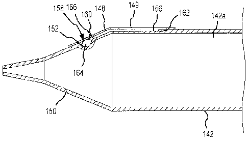
Another embodiment of a syringe 140 for installation on and use with a power
injector is illustrated in
Figures 5A-E. Hereafter, the syringe 140 will be described in conjunction with
the power injector 40 (Figures 2A-C)
although it should be appreciated that the syringe 140 may be used with any
appropriate power injector (e.g., the
power injector 10 of Figure 1) or any other appropriate injection device. In
this embodiment, the syringe 140
includes a syringe body 142 and a nozzle 146 with a frustumly-shaped or
conical transition portion 150 disposed
between the syringe body 142 and the nozzle 146. A moveable dimple 152 is
disposed on the conical transition
portion 150, such that the moveable dimple 152 is convex relative to the
inside of the conical transition portion 150
(and including in relation to the interior, fluid-containing volume of the
syringe 140, or an internal fluid discharge
chamber 142a). In addition, a channel or groove 156 may be inset into the
conical transition portion 150 and the
syringe body 142 (e.g., the channel 156 may be formed on the exterior of the
syringe 140, or such that the channel
156 is otherwise fluidly isolated from the internal fluid discharge chamber
142a). The channel 156 recedes from
the moveable dimple 152 of the conical transition portion 150 to the syringe
body 142, and then extends along at
least part of the length of the syringe body 142 (e.g., along at least about
10% of the length of the syringe body
142). An enclosed fluid source 158 (e.g., a blister pack) includes an amount
of indicator fluid 164 encapsulated
within a malleable, deformable, and/or rupturable enclosure 166. The enclosed
fluid source 158 may be disposed
17
CA 02731987 2011-01-25
WO 2010/091133 PCT/US2010/023127
within the moveable dimple 152 and below/underneath a label 148 that is
configured to cover or enclose both the
enclosed fluid source 158 and the entire length of the channel 156. The
enclosure 166 may be formed of any
appropriate substance that is sufficiently compliant so as to rupture upon
exposure to a certain amount of
pressure.
Like the syringe 110 discussed above, the syringe 140 may interact with the
syringe plunger driver
assembly 56 (Figure 2C) of the power injector 40 (Figures 2A-C) through a
syringe plunger coupler 144 of the
syringe plunger 143. When disposed in interacting relation, the syringe
plunger driver assembly 56 (Figure 2C)
may advance the syringe plunger 143 relative to the syringe body 142 so as to
discharge fluid from the nozzle 146.
As the syringe plunger 143 advances, pressure builds within the syringe body
142 and inverts the moveable
dimple 152 into a position where the dimple 152 may then be concave relative
to the inside of the conical transition
portion 150 (e.g., the interior of the syringe 140) and convex relative to the
exterior of the syringe 140. This
movement compresses the enclosed fluid source 158 between the moveable dimple
152 and the label 148 and
causes the enclosed fluid source 158 to rupture, thereby releasing the
indicator fluid 164 and allowing it to flow
along the channel 156 from the moveable dimple 152 to a distal end 162 of the
channel 156, as shown in Figures
5C and 5E.
In this embodiment, the label 148 may include a transparent portion 149 that
extends at least from a
proximal end 160 of the channel 156 to the distal end 162 of the channel 156,
such that an operator may observe
that indicator fluid 164 is present in the channel 156 and know that the
syringe 140 has been previously
discharged, To allow for prominent visual indication, the indicator fluid 164
may be any colored fluid of an
appropriate viscosity that allows the indicator fluid 164 to flow along the
channel 156.
In some instances, it may be unnecessary to dispose the enclosed fluid source
158 within a moveable
dimple 152. In general and as discussed above with respect to Figure 1, some
injection procedures may result in
a relatively high pressure being generated within the syringe. In this regard,
a syringe may be disposed within a
pressure jacket that protects the syringe from rupturing under pressure. The
pressure jacket is typically associated
with the powerhead of the power injector in a manner that allows a syringe to
be disposed therein as a part of or
after installing the syringe on the powerhead. One of ordinary skill in the
art will understand that, generally, in
instances where a pressure jacket is used in connection with the syringe, it
may become unnecessary to dispose
the enclosed fluid source or blister pack within a moveable dimple, as
discussed above. Instead, the enclosed
fluid source may be placed between the external surface of the syringe and the
internal surface of the pressure
jacket. When the syringe is pressurized, it deforms such that the enclosed
fluid source is compressed between the
exterior surface of the syringe and the interior surface of the pressure
jacket and ruptures, thereby freeing the
indicator fluid to flow along the channel. Such an embodiment is shown in
Figures 6A-E.
In greater detail, Figures 6A-E illustrate another embodiment of a syringe 170
for use with a power
injector. Hereafter, the syringe 170 will be described in conjunction with the
power injector 40 (Figures 2A-C),
although it should be appreciated that the syringe 170 may be used with any
appropriate power injector (e.g., the
power injector 10 of Figure 1). In this embodiment, the syringe 170 is
disposed within a pressure jacket 172. The
syringe 170 includes a syringe body 174 and a nozzle 176 with a frustumly-
shaped or conical transition portion 178
18
CA 02731987 2011-01-25
WO 2010/091133 PCT/US2010/023127
disposed between the syringe body 174 and the nozzle 176. A channel or groove
182 may be inset into the
conical transition portion 178 and the syringe body 174 (e.g., the channel 182
may be formed on the exterior of the
syringe 170, or such that the channel 182 is otherwise fluidly isolated from
an internal fluid discharge chamber
174a). The channel 182 extends from a proximal end 192 (e.g., located at
approximately a midpoint of the conical
transition portion 178) to a distal end 206 (e.g., located at least about 10%
down the length of the syringe body
174). The proximal end 192 of the channel 182 is configured to accommodate the
diameter of an enclosed fluid
source 184 (e.g., a blister pack). The enclosed fluid source 184 includes an
amount of indicator fluid 186
encapsulated within a malleable, deformable, and/or rupturable enclosure 188.
The enclosed fluid source 184 may
be disposed at the proximal end 192 of the channel 182 such that it protrudes
outward from the channel 182 to fill
to the gap 202 between the exterior of the conical transition portion 178 and
an inside surface 194 of the pressure
jacket 172. A label 190 may be disposed over the enclosed fluid source 184 and
extend over the length of the
channel 182. As discussed above, the enclosure 188 may be any appropriate
substance that is sufficiently
compliant so as to rupture upon the application of a certain amount of
pressure.
Like the syringes 110, 140 discussed above, the syringe 170 may interact with
the syringe plunger driver
assembly 56 (Figure 2C) of the power injector 40 (Figures2A-C) through a
syringe plunger coupler 196 of a syringe
plunger 198. When disposed in interacting relation, the syringe plunger driver
assembly 56 (Figure 2C) advances
the syringe plunger 198 relative to the syringe body 174 so as to discharge
fluid from the nozzle 176. The
resulting pressure within the syringe 170 may cause the conical transition
portion 178 of the syringe 170 to distort,
the syringe 170 to move axially relative to the pressure jacket 172, or both,
and as a result, the enclosed fluid
source 184 is pressed between the exterior of the conical transition portion
178 and an inside surface 194 of the
pressure jacket 172, thereby rupturing the enclosed fluid source 184 and
releasing the indicator fluid 186 to flow
from the proximal end 192 of the channel 182 to a distal end 206 of the
channel 182, as shown in Figures 6C and
6E.
In this embodiment, the label 190 may include a transparent portion 204 that
extends at least from the
proximal end 192 of the channel 182 to the distal end 206 of the channel 182,
such that an operator may observe
the indicator fluid 186 present in the channel 182 and know that the syringe
170 has been previously discharged.
To allow for prominent visual indication, the indicator fluid 186 may be any
colored fluid of an appropriate viscosity
that allows the indicator fluid 186 to flow along the channel 182 once the
enclosed fluid source 184 has ruptured.
Another embodiment of a syringe 210 for installation on and use with a power
injector is illustrated in
Figure 7. Hereafter, the syringe 210 will be described in conjunction with the
power injector 10 (Figure 1) although
it should be appreciated that the syringe 210 may be used with any appropriate
power injector (e.g., the power
injector 40 of Figures 2A-C). Generally, the visual indicator used by the
syringe changes states (e.g., colors) when
exposed to light of a certain wavelength or within a wavelength range. In one
embodiment, an ultraviolet (UV) light
source is utilized and the syringe 210 will be discussed with regard to the
same. Other light sources may be
appropriate.
In the Figure 7 embodiment, a section of material that is sensitive to ultra
violet ("UV") light, or a section of
UV-sensitive material 220, may be disposed between an exterior surface 214 of
a syringe body 212 and a label
19
CA 02731987 2011-01-25
WO 2010/091133 PCT/US2010/023127
222 that is at least partially transparent. The UV-sensitive material 220 may
be in the form of any material that
exhibits an optically-detectable response to exposure to UV light (e.g., UV-
sensitive adhesives, gels, foams, paints,
etc.). For example, the section of UV-sensitive material 220 may change from a
first color to a second color when
exposed to UV light.
To activate the section of UV-sensitive material 220, the powerhead 12 (Figure
1) may incorporate a UV
light source 216 in any appropriate manner that positions the UV light source
216 in a way that when flashed, the
section of UV-sensitive material 220 on the syringe body 212 is directly
exposed to a stream of UV light 226 (e.g.,
the light source 216 may be fixably or detachably mounted to the powerhead 12
via fasteners, clamps, straps,
adhesive, etc.), It should also be appreciated that the UV light source 216
may be interconnected with other
components of the power injector 10 or any other appropriate surface or
structure. In one embodiment, the light
source 216 may be a handheld unit. During an injection procedure, the UV light
source 216 may flash before or
after the power injector discharges fluid from the syringe 170, thereby
exposing the section of UV-sensitive
material 220 to UV light and causing it to transition from a first state to a
second state (e.g., from a first color to a
second color). In this regard, the UV light source 216 may be manually
activated or activation may be integrated
with an automatic injection or operations protocol such that the powerhead 12
controls the UV light source 216
(e.g. control logic may activate the light source 112 when the ram 20 is
advanced).
In one embodiment, the label 222 may be any appropriate size or shape that is
sufficient to fully contain
the section of UV-sensitive material 220 between the label 222 and the
exterior surface 214 of the syringe body
212. Specifically, beyond an offset perimeter 218, the label 222 may affix
directly to the exterior surface 214 of the
syringe body 212 so as to fully contain the section of UV-sensitive material
220 within the offset perimeter 218, as
shown in Figure 7. It should be appreciated that in other embodiments, the
offset perimeter 218 will be
unnecessary. For example, in one embodiment, the section of UV-sensitive
material 220 may be in the form of a
label adhesive that has been treated with UV-sensitive additives. In this
embodiment, the section of UV-sensitive
material 220 may span the full area beneath the label 222, which may be
partially or fully transparent to allow
some or all of the adhesive to show through the label 222. If the label 222 is
not completely transparent, it may
include at least a transparent portion 224 through which the section of UV-
sensitive material 220 is visible to an
operator who may observe the section of UV-sensitive material 220 both before
and after the syringe 210 is
exposed to UV light during an injection procedure. The transparent portion 224
may be any appropriate shape or
size to maximize visibility.
The various syringes disclosed herein may be used in conjunction with power
injectors as noted. They
may be appropriate for use with other injection devices as well. For instance,
each of the syringes disclosed
herein may be used with the type of hand-held, hand-powered injectors of the
type disclosed by U.S. Patent No.
7,041,084, entitled "HAND-HELD, HAND OPERATED POWER SYRINGE AND METHODS," and
that issued on
May 9, 2006.
The foregoing description of the present invention has been presented for
purposes of illustration and
description. Furthermore, the description is not intended to limit the
invention to the form disclosed herein.
Consequently, variations and modifications commensurate with the above
teachings, and skill and knowledge of
CA 02731987 2011-01-25
WO 2010/091133 PCT/US2010/023127
the relevant art, are within the scope of the present invention. The
embodiments described hereinabove are
further intended to explain best modes known of practicing the invention and
to enable others skilled in the art to
utilize the invention in such, or other embodiments and with various
modifications required by the particular
application(s) or use(s) of the present invention. It is intended that the
appended claims be construed to include
alternative embodiments to the extent permitted by the prior art.
21