Note: Descriptions are shown in the official language in which they were submitted.
CA 02732043 2011-01-26
WO 2010/014563
PCT/US2009/051888
MAGNETIC FLUID SEAL WITH SHUNT ELEMENT
BACKGROUND OF THE INVENTION
1. Description of the Related Art
[0001] The present invention relates to magnetic fluid seal systems.
2. Description of the Known Technology
[0001] Magnetic fluid seals generally include a rotatable shaft and a
unitized
sub-assembly of ring magnets and pole rings. Dimensions are controlled to
produce
small annular gaps between pole ring tips and the shaft surface. Strong
magnetic
fields exist in these gaps. A small amount of ferrofluid is added at each gap
and is
held by the field as liquid rings in the gaps, with gas-filled spaces confined
between
adjacent rings. The number of magnets and annular gaps may vary and the pole
rings may, in fact, be formed as a single pole piece. Whatever the detailed
design
may be, all such devices perform their sealing function as described in the
next
paragraph.
[0002] If pressure is the same on both sides of a fluid ring, the fluid
assumes
an equilibrium position determined by the strength and configuration of the
local
magnetic field. Any difference in pressure from one side of a fluid ring to
the other
tends to displace the fluid axially from its equilibrium position. Displacing
a ring from
its equilibrium position leads to a net axial force that opposes the pressure
difference
that produced the displacement. If the pressure difference becomes large
enough,
the liquid ring bursts open, and gas flows from one side of the gap to the
other. The
pressure at which the ring bursts is called the "pressure capacity" of the
ring. The
pressure capacity of a multi-stage device (i.e. multiple liquid rings arranged
in series
1
CA 02732043 2015-09-18
on the same shaft) is the sum of the pressure capacities of individual stages.
As
fluid seals are utilized in environments of significant pressure difference,
increasing
the pressure capacity of ferrofluid seals is highly desirable.
BRIEF SUMMARY OF THE INVENTION
[0003] In overcoming the drawbacks of the prior art, a magneto-fluidic
seal
includes a shaft, a pole piece, and a plurality of sealing fluid rings located
between
the shaft and the pole piece. The sealing fluid rings may be defined by the
shaft
and/or the pole piece and contain a ferromagnetic fluid. At least one channel
having a bottom is defined by either the shaft or the pole piece. A shunt is
located
directly adjacent to the bottom of the channel. The thickness of the shunt is
based
on the energy differential in the plurality of sealing fluid rings as the
fluid is
displaced from one side of the sealing fluid rings to the other side of the
sealing
fluid rings.
[0003.1] In accordance with one aspect of the present invention, there is
provided a magneto-fluidic seal comprising a shaft; a pole piece, wherein a
radial
gap is located between the shaft and the pole piece; at least one channel
defined
by either the shaft or the pole piece, the annular channel having a bottom; a
plurality of sealing fluid rings located between the shaft and the pole piece,
the
sealing fluid rings containing a ferromagnetic fluid; a shunt wall being
located
directly adjacent to the bottom of the channel, the shunt wall having a
thickness,
the thickness of the shunt is either defined by (a) the distance between the
bottom
of the channel and a center line of the shaft or (b) the distance between the
bottom
of the channel and an inner diameter of the pole piece; at least one magnet
being
located within the at least one channel; wherein the thickness of the shunt
wall is
based on the energy differential in the plurality of sealing fluid rings as
the fluid is
displaced from one side of the sealing fluid rings to the other side of the
sealing
fluid rings; wherein comfortably large magnetic fields in sealing gaps are
achieved
while still maintaining a shunt wall thickness large enough to provide
strength and
2
CA 02732043 2015-09-18
vacuum integrity; a plurality of grooves located on either shaft or the pole
piece;
and wherein a groove depth of the plurality of grooves is at least four times
the
radial gap between the shaft and the pole piece.
[0004] Further objects, features and advantages of this invention will
become readily apparent to persons skilled in the art after a review of the
following
description, with reference to the drawings and claims that are appended to
and
form a part of this specification.
BRIEF DESCRIPTION OF THE DRAWINGS
[0005] Figure 1 illustrates a Satwall configuration of a magneto-fluidic
seal;
[0006] Figure 2 illustrates a more detailed view of the magneto-fluidic
seal
of Figure 1;
[0007] Figure 3 illustrates a Superseal configuration of a magneto-
fluidic
seal;
[0008] Figures 4A-4D illustrate different embodiments of magneto-fluidic
seals with shunt walls; and
2a
CA 02732043 2011-01-26
WO 2010/014563
PCT/US2009/051888
[0009] Figures
5 and 6 illustrate a more detailed view of the magneto-fluidic
seal of Figure 4D.
DETAILED DESCRIPTION OF THE INVENTION
[0010]
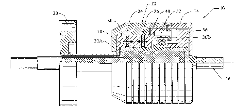
Referring to Figure 1, a first embodiment of the invention is shown in a
"Satwall" configuration. Here, a
magneto-fluidic seal 10 according to this
embodiment is housed in a generally cylindrical housing comprising an aluminum
housing 12 and aluminum end cap 34. A rotatable shaft 16 is inserted through a
central opening in the end cap 34. The left end of the shaft 16 extends
through an
opening in flange 20 which is adapted to mount the magneto-fluidic seal 10 in
a
vacuum environment at elevated temperatures. The right end thereof as viewed
in
Figure 1, is adapted to be disposed in a normal atmospheric environment at
ambient
temperatures. Note, since the device is radially symmetric, only the top half
is shown
in detail in Figure 1. A single cross-roller bearing 32 secured by aluminum
bearing
nut 36 rotatably holds shaft 16 and provides a large resistance against force
moments which would tend to tilt the shaft 16.
[0011] Within
the housing, alternately disposed in series in the axial direction,
are at least a pair of permanent magnets 24 and 26 separated by an annular
pole
piece 30.
[0012] Pole
piece 30 is formed from magnetic stainless steel. On its outside
diameter, the pole piece contains two channels 38 and 40 which are deep enough
to
fully contain magnets 24 and 26, efficiently capturing magnetic flux from the
magnets. A unitary pole piece with segmented or button-shaped magnets 24 and
26
inserted into the channels 38 and 40 is the preferred construction, but it is
also
possible to use a built-up pole piece (central tube with outer rings slipped
onto it)
3
CA 02732043 2011-01-26
WO 2010/014563
PCT/US2009/051888
and full ring magnets. The unitary construction is preferred because
manufacturing
costs will be lower, since (a) only a single machined piece is required, and
(2) a
single standardized magnet component (button or segment) can be used in many
different magnetic assemblies.
[0013] The pole
piece 30 contains a first cylindrical cavity 30A ("sealing
cavity") of diameter slightly larger than the outside diameter of shaft 16,
and a
second cavity ("bearing mount cavity") 30B. These cavities are coaxial,
thereby
establishing the overall alignment of the shaft 16, bearing region 30B and
sealing
region 30A.
[0014] The
magnets 24 and 26 are arranged so that the polarity of the
magnets on opposite side of the pole piece 30 is symmetrical with respect to
the
pole piece; i.e., the polarity of the opposite surfaces of the two adjoining
magnets is
the same as each other.
[0015] In
Figure 2, the shunt wall sections 42 of pole piece are shown. If a
unitary pole piece construction is used, these sections are formed as an
integral part
of the pole piece. The magnet-holding channels or gaps 38 and 40 are machined
to
a depth that will be described later in the paragraphs that follow.
[0016] These
shunt walls 42 are strong enough to support the pressure
difference across the device, i.e., between atmosphere and vacuum, while thin
enough to become magnetically saturated by the two ring magnets 24 and 26. If
very
high saturation of the walls 42 is achieved, then the remaining magnetic
energy will
be sufficient to produce sufficient high flux levels to seal gaps 50.
[0017] Computer
simulation of the magnetic system was used to find a
combination of design parameters which would allow a shunt wall to be used,
while
4
CA 02732043 2011-01-26
WO 2010/014563
PCT/US2009/051888
still providing high magnetic fields in the sealing gaps. A range of design
parameters
was found over which it was possible to achieve comfortably large magnetic
fields in
the sealing gaps while still maintaining shunt wall thickness large enough to
provide
the strength and vacuum integrity required. More specifically, the following
parameters and ranges may be used:
a) The magnets 24 and 26 used were rare earth magnets (e.g., SmCo or
NdBFe), with an energy product of 18 MGO or greater, formed in the shape of
buttons 9.0 mm diameter x2.0 mm thick.
b) The recommended pole piece material is magnetic stainless steel, e.g., 17-
4PH, or any 400-series stainless steel.
c) The number of shaft grooves 44 should be a minimum of 4 and preferably 8
to 15. Groove depths of 0.5 mm and widths of 0.5 mm, with 0.5 mm spacing
between grooves are preferred. The groove depth should be at least four
times the radial gap between shaft and pole piece.
[0018] When the
device is assembled and end cap 34 is joined to housing 12
by an epoxy or other adhesive, a measured amount of ferromagnetic fluid
(sufficient
to fill a limited number of sealing gaps 50) is placed on the shaft in the
"secondary
sealing region" 46, and the shaft 16 is inserted into the pole piece 30. When
the
fluid-wetted section enters the pole piece, the fluid spreads evenly around
the shaft
16 filling the gaps and forming isolated pockets of trapped air in the sealing
gaps or
grooves 50 of the shaft. A pressure differential is applied across the
assembly
(vacuum pumping on the flanged end), and some fluid is drawn further into the
"primary sealing region" 28. It has been determined that only a few (e.g.,
four)
stages are required to support the full pressure differential (1 atmosphere),
provided
CA 02732043 2011-01-26
WO 2010/014563
PCT/US2009/051888
the magnetic field strength is high enough, in the "primary sealing region."
The
sealing gaps 44 in the "secondary sealing region" also provide some degree of
sealing, although these stages will be weaker than in the "primary sealing
region,"
because the field strength in these gaps is less.
[0019]
Referring to Figure 3 of the drawings, a second embodiment of a
magneto-fluidic seal 110, shown in longitudinal half-section, will be
described in
detail in connection therewith. It should be understood that like reference
numerals
will be utilized to describe like components ¨ with the exception that these
reference
numerals will be preceded with the numeral "1." It should be further
understood that
the device is symmetric and that therefore only the upper half section needs
to be
shown. This type of configuration is generally referred to as a "Satwall"
configuration.
[0020] A
generally cylindrical housing 112 extends through and is affixed to
barrier wall 129. The housing 112 encircles a rotary shaft 116 which is
inserted
through a central portion of the housing in an axial direction.
[0021] A
central section 117 of the shaft 116 is formed with two channels 138
and 140 for containing magnets 124 and 126, respectively. The central section
117
also includes five shaft grooves 144 defining pole rings 129 and shoulders 123
against which bearings 132 are mounted. Preferably, the bearings 132 are
disposed
so as to straddle the sealing region which extends axially between the
shoulders
123. Essentially, the pole piece 130 is defined by the shaft 116.
[0022]
Preferably, shaft 116 is formed of ferromagnetic material suitable for
use in the intended process (vacuum) environment in which one end of the shaft
is
exposed to the atmosphere, and the opposite end extends through a barrier 129
to a
vacuum environment.
6
CA 02732043 2011-01-26
WO 2010/014563
PCT/US2009/051888
[0023] The
function of the grooves is to define several distinct pole gaps 127
(in this case eight) spaced axially apart from each other. The magnets 124 and
126
are inserted into the channels 138 and 140 of the shaft 116. The magnets 124
and
126 may be half sectors of the ring magnets or may be small cylinders or any
of
several sector shapes. All magnets in a single channel have their magnetic
polar
orientation in the same direction. Preferably magnets in the second channel
are
oriented with magnetic polarity opposite to the magnets in the first channel.
This
opposed-polarity condition results in a finished assembly with enhanced
magnetic
flux in the sealing gaps and minimum external magnetic field as will be
explained
below.
[0024] Magnets
124 and 126 must be positively retained in the channels in
order to prevent them from sliding out as a result of mutual magnetic
repulsion or
centrifugal force. The means of retention is not shown here. Typical retention
methods would be (1) epoxy to secure the magnets in the grooves, (2) a thin
wire or
band placed as a hoop around the magnets or (3) rolled edges on the magnet
channels. In any case, the retaining means must not extend radially beyond the
slot
boundary, or it will contact the housing inner surface during rotation.
[0025] To
further illustrate other embodiments of the invention, Figures 4A-4D
are provided. Figures 4A-4D illustrate simplified embodiments of magneto-
fluidic
seals so as to bring attention to differing variations. It should be
understood that like
reference numerals will be utilized to describe like components, with the
exception
that these reference numerals will be preceded with the numeral "2" and
followed by
the letters "A-D." The letterers "A-D" relate to components shown in Figures
4A-4D,
7
CA 02732043 2011-01-26
WO 2010/014563
PCT/US2009/051888
respectively. Like the other Figures, it should be further understood that the
device
is symmetric and that therefore only the upper half section needs to be shown.
[0026] Magneto-
fluidic seals 210A-210D each include shafts 216A-216D and
pole pieces 230A-230D. However, in FIGS 4A and 4B, channels 238A, 238B, 240A
and 240B are formed in the shafts 216A and 216B. Conversely, in Figures 4C and
4D, channels 238C, 238D, 240C and 240D are formed in the pole pieces 230C and
230D.
[0027] Also,
Figures 4A and 4C include grooves 244A and 244C formed and
defined by the shafts 216A and 216C, respectively. Conversely, Figures 4B and
4D
include grooves 244B and 244D formed and defined by the pole pieces 230B and
230D, respectively. Therefore, from the description of Figures 4A-4D, it
should be
clear that the grooves and/or the channels can be formed on either the pole
pieces
or the shafts.
[0028] Still
referring to Figures 4A-4D, the shunt walls 242A-242D are formed
on either the shafts 216A and 216B or on the pole pieces 230C and 230D. More
specifically, the channels 238A-238D and 240A-240D each have a bottom 248A-
248D and a top 249A-249D, respectively. As explained previously, channels 238A-
238D and 240A-240D are defined by either the shafts 216A-216B or the pole
pieces
230C-230D.
[0029] The
shunt walls 242A-242D each have a thickness. In the case where
the shunt walls 242A-242B are defined by the shafts 216A and 216B, the
thickness
of the shunt walls 242A-242B are each defined by the distance between the
bottoms
248A-248B of the channels 224A, 226A, 224B and 226B and a center line (axis)
of
the shafts 216A-216B, represented by line 252A and 252B. In the case where the
8
CA 02732043 2011-01-26
WO 2010/014563
PCT/US2009/051888
shunt walls 242C-242D are defined by the pole pieces 230C and 230D, the
thickness of the shunt walls 242C-242D are each defined by the distance
between
the bottoms 248C-248D of the channels 224C, 226C, 224D and 226D and the inner
diameters 227C and 227D of the pole pieces 230C and 230D.
[0030] The
pressure capacity of ferrofluid seals can be improved by adjusting
the thickness of the shunt walls 242A-242D. Some benefits and advantages of
this
design approach are: (1) the pressure capacity can be maximized for both
Satwall
and Superseal devices by selecting the best dimensions for magnets and shunt
elements; (2) the force required to overcome viscous drag in the ferrofluid
rings is
reduced; (3) the wall thicknesses and manufacturing tolerances for Satwall
pole
pieces are greatly relaxed as compared to the traditional design rule, which
states
that the shunting wall should be as thin as possible; (4) in Satwall devices
that
impose mechanical loads (torsion or bending) on the shunting wall, the
strength is
very greatly increased over thin-walled devices; (5) in Superseal devices,
smaller
magnets can be used, thereby reducing the diameter of the sealing fluid rings.
[0031] This
makes the devices more compact and reduces friction and self-
heating when the shafts are turned; and (6) in coaxial devices (two or more
concentric shafts on a common axis) the benefits listed in items 3 and 4 are
both in
effect, leading to very compact devices with very high shaft strength.
[0032] The
major difficulties overcome in the course of developing this
innovation have to do with the complexity of calculating magnetic fields and
forces in
anything other than very simple structures. Simple design methods are not
adequate to deal with the complexity of real systems. Finite element analysis
("FEA") allows the magnetic fields to be determined throughout the ferrofluid
sealing
9
CA 02732043 2011-01-26
WO 2010/014563
PCT/US2009/051888
device. The FEA modeling and analysis procedures used to discover and demon-
strate this innovation are a combination of (1) well known modeling ideas,
(2) commercially available software, and (3) proprietary implementation of the
commercially available tools. Post-processing of data from the FEA solutions
is
critically important as well, and has been done by a proprietary method.
[0033]
Referring to Figure 5, a more detailed view of the embodiment shown
in Figure 4D is shown. Figure 5 illustrates the approximate location of the
fluid rings
when there is no pressure difference across any sealing stage. Although the
exact
shape of the free surface at each side of each ring depends on the shape of
the
magnetic field in this region, the fluid will be distributed approximately
equally on
either side of the pole tip.
[0034] When
there is a pressure difference across the sealing stage, the
distribution becomes approximately as shown in Figure 6. In this illustration,
the
high pressure side is toward the right. Some fluid is displaced from the high
pressure side of each fluid ring toward the low pressure side.
[0035] The
magnetic fields in the fluid regions are no longer symmetrical and
balanced on the two sides of each fluid ring. Locations nearest to a gap will
have
larger field magnitudes and gradients than locations farther away from that
gap.
This will result in a net force that tends to pull the left side of the fluid
ring back
toward the gap. This force is in a direction that opposes the pressure
difference that
displaced fluid in the first place. This restoring force is what supports some
pressure
difference across the sealing stage.
[0036] From
elementary physics it is known that whenever any object is
moved against an opposing force, physical work is done (Work = Force x
Distance).
CA 02732043 2011-01-26
WO 2010/014563
PCT/US2009/051888
So some work must be done to effect the fluid displacement illustrated here.
According to the principle of Work-Energy Equivalence, this work results in an
altered energy state for the fluid ring. If the magnetic field throughout the
fluid region
before and after the displacement is known, one can apply well known
procedures to
calculate the energies before and after displacement. Once both the energy
change
(4E) and the displacement are known, one can calculate the force that must
have
been required to produce that energy change. Taking into account the shape of
the
fluid, one can compute the pressure that corresponds to this force. For the
condition
of full displacement, this force will be the "pressure capacity".
[0037] Note
that the change in energy, AE, is important, and not the energy
itself AE depends on both: (1) the strength of the magnetic field and (2) the
field
gradient (how rapidly it changes). A ferromagnetic object experiences zero
force
when it is moved about in a strong field that is absolutely uniform (zero
gradient).
Even though the magnetic energy in the object is large, there is no change in
energy
due to the change in location. Hence, there is no force. Some change in field
strength with change in location (i.e. a field gradient) must exist in order
to have a
change in energy.
[0038] This
implies that the way to maximize pressure capacity is to establish
a magnetic field configuration that maximizes AE in the fluid rings over their
range of
displacement. While strong magnetic fields are desirable, it is advisable to
also
establish strong gradients as well. It is possible to use very strong magnetic
materials and, by means of a magnetic shunt region that diverts some energy
away
from the fluid region, alter the shape and strength of the field and gradient
to
maximize AE in the fluid region. Field strength is reduced, but gradient is
increased
11
CA 02732043 2015-09-18
as shunt dimensions increase, but only up to a point. If too much energy is
diverted
through the shunt, dE will decline (because the fields in the fluid will be
too small),
and the pressure capacity will fall. So there is some optimum set of
dimensions for
the shunting region. At this optimum, dE is maximized, and so is the pressure
capacity.
[0039] As a person
skilled in the art will readily appreciate, the above
description is meant as an illustration of implementation of the principles
this
invention. The scope of the claims should not be limited by the preferred
embodiments set forth in the examples, but should be given the broadest
interpretation consistent with the description as a whole.
12