Language selection

Search

Patent 2732046 Summary

Third-party information liability

Some of the information on this Web page has been provided by external sources. The Government of Canada is not responsible for the accuracy, reliability or currency of the information supplied by external sources. Users wishing to rely upon this information should consult directly with the source of the information. Content provided by external sources is not subject to official languages, privacy and accessibility requirements.

Claims and Abstract availability

Any discrepancies in the text and image of the Claims and Abstract are due to differing posting times. Text of the Claims and Abstract are posted:

  • At the time the application is open to public inspection;
  • At the time of issue of the patent (grant).
(12) Patent: (11) CA 2732046
(54) English Title: LIQUEFIED NATURAL GAS PRODUCTION
(54) French Title: PRODUCTION DE GAZ NATUREL LIQUEFIE
Status: Deemed expired
Bibliographic Data
(51) International Patent Classification (IPC):
  • F25J 3/00 (2006.01)
(72) Inventors :
  • WILKINSON, JOHN D. (United States of America)
  • HUDSON, HANK M. (United States of America)
  • CUELLAR, KYLE T. (United States of America)
(73) Owners :
  • ORTLOFF ENGINEERS, LTD. (United States of America)
(71) Applicants :
  • ORTLOFF ENGINEERS, LTD. (United States of America)
(74) Agent: GOWLING WLG (CANADA) LLP
(74) Associate agent:
(45) Issued: 2015-02-10
(86) PCT Filing Date: 2009-07-28
(87) Open to Public Inspection: 2010-02-11
Examination requested: 2014-01-16
Availability of licence: N/A
(25) Language of filing: English

Patent Cooperation Treaty (PCT): Yes
(86) PCT Filing Number: PCT/US2009/051901
(87) International Publication Number: WO2010/017061
(85) National Entry: 2011-01-26

(30) Application Priority Data:
Application No. Country/Territory Date
61/086,702 United States of America 2008-08-06
12/479,061 United States of America 2009-06-05

Abstracts

English Abstract


A process and an apparatus for liquefying a portion of a natural gas stream
are disclosed. The natural gas stream is
cooled under pressure and divided into a first stream and a second stream. The
first stream is cooled, expanded to an intermediate
pressure, and supplied to a lower feed point on a distillation column. The
second stream is expanded to the intermediate pressure
and divided into two portions. One portion is cooled and then supplied to a
mid-column feed point on the distillation column; the
other portion is used to cool the first stream. The bottom product from this
distillation column preferentially contains the majority
of any hydrocarbons heavier than methane that would otherwise reduce the
purity of the liquefied natural gas, so that the overhead
vapor from the distillation column contains essentially only methane and
lighter components.


French Abstract

Processus et dispositif destinés à liquéfier une partie d'un flux de gaz naturel. Ce flux de gaz naturel est refroidi sous pression et divisé en un premier flux et en un second flux. Le premier flux est refroidi, dilaté pour atteindre une pression intermédiaire, et acheminé à un point d'alimentation inférieur sur une colonne de distillation. Le second flux est dilaté pour atteindre l'état de pression intermédiaire et divisé en deux parties. Une partie est refroidie puis acheminée à un point d'alimentation à mi-colonne sur la colonne de distillation; l'autre partie est utilisée pour refroidir le premier flux. Il est souhaitable que le produit du fond de cette colonne de distillation contienne une majorité d'hydrocarbures plus lourds que le méthane, car autrement, ils pourraient réduire la pureté du gaz naturel liquéfié, de façon à ce que la vapeur qui s'élève de la colonne de distillation ne contienne pratiquement que du méthane et des composants plus légers.

Claims

Note: Claims are shown in the official language in which they were submitted.


We claim:

1. A process for liquefying a portion of a natural gas stream containing
methane and
heavier hydrocarbon components to produce a liquefied natural gas stream
wherein
(a) said natural gas stream is cooled sufficiently to partially condense it
and is
thereafter divided into at least a first gaseous stream and a second gaseous
stream;
(b) said first gaseous stream is further cooled and is thereafter expanded
to an
intermediate pressure, whereupon said expanded cooled first gaseous stream is
supplied at a lower feed position to a distillation column that produces an
overhead vapor stream and a bottom liquid stream;
(c) said second gaseous stream is separated into a vapor stream and a
liquid stream;
(d) said vapor stream is expanded to said intermediate pressure and is
thereafter
divided into at least a first portion and a second portion;
(e) said first portion is cooled and is thereafter supplied to said
distillation column at
a mid-column feed position;
(f) said second portion is heated, with said heating supplying at
least a portion of said
cooling of one or more of said natural gas stream and said first gaseous
stream;
(g) said overhead vapor stream is cooled sufficiently to at least partially
condense it
and form thereby a condensed stream;
(h) said condensed stream is divided into at least a feed stream and a
reflux stream,
whereupon said reflux stream is supplied to said distillation column at a top
column feed position;
(i) said feed stream is further cooled and is thereafter expanded to lower
pressure;
(i) said expanded further cooled feed stream is separated into a first
flash vapor
stream and a flash liquid stream;
(k) said flash liquid stream is expanded to still lower pressure;
(l) said expanded flash liquid stream is separated into a second flash
vapor stream
and said liquefied natural gas stream;
(m) said second flash vapor stream is heated, with said heating
supplying at least a
portion of said cooling of one or more of said natural gas stream, said first
portion, said overhead vapor stream, and said feed stream;
- 16 -


(n) said first flash vapor stream is heated, with said heating supplying at
least a
portion of said cooling of said feed stream;
(o) said bottom liquid stream is expanded to said lower pressure, whereupon
said
expanded bottom liquid stream is combined with said heated first flash vapor
stream to form a first combined stream;
(p) said first combined stream is heated, with said heating supplying at
least a portion
of said cooling of one or more of said first portion and said overhead vapor
stream;
(q) said liquid stream is expanded to said lower pressure, whereupon said
expanded
liquid stream is combined with said heated first combined stream to form a
second combined stream; and
(r) said second combined stream is heated, with said heating supplying at
least a
portion of said cooling of said natural gas stream.
2. A process for liquefying a portion of a natural gas stream
containing methane and
heavier hydrocarbon components to produce a liquefied natural gas stream
wherein
(a) said natural gas stream is divided into at least a first gaseous stream
and a second
gaseous stream;
(b) said first gaseous stream is cooled and is thereafter expanded to an
intermediate
pressure, whereupon said expanded cooled first gaseous stream is supplied at a

lower feed position to a distillation column that produces an overhead vapor
stream and a bottom liquid stream;
(c) said second gaseous stream is cooled sufficiently to partially condense
it and is
thereafter separated into a vapor stream and a liquid stream;
(d) said vapor stream is expanded to said intermediate pressure and is
thereafter
divided into at least a first portion and a second portion;
(e) said first portion is cooled and is thereafter supplied to said
distillation column at
a mid-column feed position;
(f) said second portion is heated, with said heating supplying at
least a portion of said
cooling of one or more of said first gaseous stream and said second gaseous
stream;
- 17 -


(g) said overhead vapor stream is cooled sufficiently to at least partially
condense it
and form thereby a condensed stream;
(h) said condensed stream is divided into at least a feed stream and a
reflux stream,
whereupon said reflux stream is supplied to said distillation column at a top
column feed position;
(i) said feed stream is further cooled and is thereafter expanded to lower
pressure;
(i) said expanded further cooled feed stream is separated into a first
flash vapor
stream and a flash liquid stream;
(k) said flash liquid stream is expanded to still lower pressure;
(l) said expanded flash liquid stream is separated into a second flash
vapor stream
and said liquefied natural gas stream;
(m) said second flash vapor stream is heated, with said heating supplying
at least a
portion of said cooling of one or more of said first gaseous stream, said
second
gaseous stream, said first portion, said overhead vapor stream, and said feed
stream;
(n) said first flash vapor stream is heated, with said heating supplying at
least a
portion of said cooling of said feed stream;
(o) said bottom liquid stream is expanded to said lower pressure, whereupon
said
expanded bottom liquid stream is combined with said heated first flash vapor
stream to form a first combined stream;
(p) said first combined stream is heated, with said heating supplying at
least a portion
of said cooling of one or more of said first portion and said overhead vapor
stream;
(q) said liquid stream is expanded to said lower pressure, whereupon said
expanded
liquid stream is combined with said heated first combined stream to form a
second combined stream; and
(r) said second combined stream is heated, with said heating supplying at
least a
portion of said cooling of one or more of said first gaseous stream and said
second
gaseous stream.
- 18 -


3. A process for liquefying a portion of a natural gas stream containing
methane and
heavier hydrocarbon components to produce a liquefied natural gas stream
wherein
(a) said natural gas stream is cooled sufficiently to partially condense it
and is
thereafter divided into at least a first gaseous stream and a second gaseous
stream;
(b) said first gaseous stream is further cooled and is thereafter expanded
to an
intermediate pressure, whereupon said expanded cooled first gaseous stream is
supplied at a lower feed position to a distillation column that produces an
overhead vapor stream and a bottom liquid stream;
(c) said second gaseous stream is separated into a vapor stream and a
liquid stream;
(d) said vapor stream is expanded to said intermediate pressure and is
thereafter
divided into at least a first portion and a second portion;
(e) said first portion is cooled and is thereafter supplied to said
distillation column at
a mid-column feed position;
(f) said second portion is heated, with said heating supplying at
least a portion of said
cooling of one or more of said natural gas stream and said first gaseous
stream;
(g) said overhead vapor stream is cooled sufficiently to at least partially
condense it
and form thereby a condensed stream;
(h) said condensed stream is divided into at least a feed stream and a
reflux stream,
whereupon said reflux stream is supplied to said distillation column at a top
column feed position;
(i) said bottom liquid stream is expanded to lower pressure, whereupon said

expanded bottom liquid stream is heated, with said heating supplying at least
a
portion of said cooling of one or more of said first portion and said overhead

vapor stream;
(i) said feed stream is expanded to still lower pressure;
(k) said expanded feed stream is separated into a flash vapor stream
and said
liquefied natural gas stream;
(l) said flash vapor stream is heated, with said heating supplying at
least a portion of
said cooling of one or more of said natural gas stream, said first portion,
and said
overhead vapor stream;
- 19 -


(m) said liquid stream is expanded to said lower pressure, whereupon said
expanded
liquid stream is combined with said heated expanded bottom liquid stream to
form
a combined stream; and
(n) said combined stream is heated, with said heating supplying at least a
portion of
said cooling of said natural gas stream.
4. A process for liquefying a portion of a natural gas stream
containing methane and
heavier hydrocarbon components to produce a liquefied natural gas stream
wherein
(a) said natural gas stream is divided into at least a first gaseous stream
and a second
gaseous stream;
(b) said first gaseous stream is cooled and is thereafter expanded to an
intermediate
pressure, whereupon said expanded cooled first gaseous stream is supplied at a

lower feed position to a distillation column that produces an overhead vapor
stream and a bottom liquid stream;
(c) said second gaseous stream is cooled sufficiently to partially condense
it and is
thereafter separated into a vapor stream and a liquid stream;
(d) said vapor stream is expanded to said intermediate pressure and is
thereafter
divided into at least a first portion and a second portion;
(e) said first portion is cooled and is thereafter supplied to said
distillation column at
a mid-column feed position;
(f) said second portion is heated, with said heating supplying at
least a portion of said
cooling of one or more of said first gaseous stream and said second gaseous
stream;
(g) said overhead vapor stream is cooled sufficiently to at least partially
condense it
and form thereby a condensed stream;
(h) said condensed stream is divided into at least a feed stream and a
reflux stream,
whereupon said reflux stream is supplied to said distillation column at a top
column feed position;
(i) said bottom liquid stream is expanded to lower pressure, whereupon
said
expanded bottom liquid stream is heated, with said heating supplying at least
a
- 20 -


portion of said cooling of one or more of said first portion and said overhead

vapor stream;
(i) said feed stream is expanded to still lower pressure;
(k) said expanded feed stream is separated into a flash vapor stream
and said
liquefied natural gas stream;
(l) said flash vapor stream is heated, with said heating supplying at
least a portion of
said cooling of one or more of said first gaseous stream, said second gaseous
stream, said first portion, and said overhead vapor stream;
(m) said liquid stream is expanded to said lower pressure, whereupon said
expanded
liquid stream is combined with said heated expanded bottom liquid stream to
form
a combined stream; and
(n) said combined stream is heated, with said heating supplying at least a
portion of
said cooling of one or more of said first gaseous stream and said second
gaseous
stream.
5. The process according to claim 1 or 2 wherein
(a) said flash liquid stream is cooled before it is expanded to said still
lower pressure;
and
(b) said heating of said second flash vapor stream also supplies at least a
portion of
said cooling of said flash liquid stream.
6. The process according to claim 3 or 4 wherein
(a) said feed is cooled before it is expanded to said still lower pressure;
and
(b) said heating of said flash vapor stream also supplies at least a
portion of said
cooling of said feed stream.
7. An apparatus for liquefying a portion of a natural gas stream
containing methane
and heavier hydrocarbon components to produce a liquefied natural gas stream
comprising
(a) first heat exchange means connected to receive said natural gas
stream and cool it
sufficiently to partially condense it;
- 21 -


(b) first dividing means connected to receive said partially condensed
natural gas
stream and divide it into at least a first gaseous stream and a second gaseous

stream;
(c) second heat exchange means connected to said first dividing means to
receive said
first gaseous stream and further cool it;
(d) first expansion means connected to said second heat exchange means to
receive
said further cooled first gaseous stream and expand it to an intermediate
pressure,
said first expansion means being further connected to a distillation column to

supply said expanded further cooled first gaseous stream at a lower feed
position;
(e) first separation means connected to said first dividing means to
receive said
second gaseous stream and separate it into a vapor stream and a liquid stream;
(f) second expansion means connected to said first separation means to
receive said
vapor stream and expand it to said intermediate pressure;
(g) second dividing means connected to said second expansion means to
receive said
expanded vapor stream and divide it into at least a first portion and a second

portion;
(h) third heat exchange means connected to said second dividing means to
receive
said first portion and cool it, said heat exchange means being further
connected to
said distillation column to supply said cooled first portion at a mid-column
feed
position;
(i) said second heat exchange means further connected to said second
dividing means
to receive said second portion and heat it, with said heating supplying at
least a
portion of said further cooling of said first gaseous stream;
(i) first withdrawing means connected to an upper region of said
distillation column
to withdraw an overhead vapor stream;
(k) said third heat exchange means further connected to said first
withdrawing means
to receive said overhead vapor stream and cool it sufficiently to at least
partially
condense it and form thereby a condensed stream;
(l) third dividing means connected to said third heat exchange means to
receive said
condensed stream and divide it into at least a feed stream and a reflux
stream, said
- 22 -


third dividing means being further connected to said distillation column to
supply
said reflux stream to said distillation column at a top column feed position;
(m) fourth heat exchange means connected to said third dividing means to
receive said
feed stream and further cool it;
(n) third expansion means connected to said fourth heat exchange means to
receive
said further cooled feed stream and expand it to lower pressure;
(o) second separation means connected to said third expansion means to
receive said
expanded further cooled feed stream and separate it into a first flash vapor
stream
and a flash liquid stream;
(p) fourth expansion means connected to said second separation means to
receive said
flash liquid stream and expand it to still lower pressure;
(q) third separation means connected to said fourth expansion means to
receive said
expanded flash liquid stream and separate it into a second flash vapor stream
and
said liquefied natural gas stream;
(r) said fourth heat exchange means further connected to said third
separation means
to receive said second flash vapor stream and heat it, with said heating
supplying
at least a portion of said further cooling of said feed stream;
(s) said fourth heat exchange means further connected to said second
separation
means to receive said first flash vapor stream and heat it, with said heating
supplying at least a portion of said further cooling of said feed stream;
(t) second withdrawing means connected to a lower region of said
distillation colunm
to withdraw a bottom liquid stream;
(u) fifth expansion means connected to said second withdrawing means to
receive
said bottom liquid stream and expand it to said lower pressure;
(v) first combining means connected to said fifth expansion means and to
said fourth
heat exchange means to receive said expanded bottom liquid stream and said
heated first flash vapor stream, respectively, and form thereby a first
combined
stream;
(w) said third heat exchange means further connected to said first
combining means to
receive said first combined stream and heat it, with said heating supplying at
least
- 23 -


a portion of said cooling of one or more of said first portion and said
overhead
vapor stream;
(x) sixth expansion means connected to said first separation means to
receive said
liquid stream and expand it to said lower pressure;
(y) second combining means connected to said sixth expansion means and to
said
third heat exchange means to receive said expanded liquid stream and said
heated
first combined stream, respectively, and form thereby a second combined
stream;
and
(z) said first heat exchange means further connected to said second
combining means
to receive said second combined stream and heat it, with said heating
supplying at
least a portion of said cooling of said natural gas stream.
8. An apparatus for liquefying a portion of a natural gas stream
containing methane
and heavier hydrocarbon components to produce a liquefied natural gas stream
comprising
(a) first dividing means connected to receive said natural gas stream and
divide it into
at least a first gaseous stream and a second gaseous stream;
(b) first heat exchange means connected to receive said first gaseous
stream and cool
it;
(c) second heat exchange means connected to said first heat exchange means
to
receive said cooled first gaseous stream and further cool it;
(d) first expansion means connected to said second heat exchange means to
receive
said further cooled first gaseous stream and expand it to an intermediate
pressure,
said first expansion means being further connected to a distillation column to

supply said expanded further cooled first gaseous stream at a lower feed
position;
(e) said first heat exchange means further connected to receive said second
gaseous
stream and cool it sufficiently to partially condense it;
first separation means connected to said first heat exchange means to receive
said
partially condensed second gaseous stream and separate it into a vapor stream
and
a liquid stream;
(g) second expansion means connected to said first separation means to
receive said
vapor stream and expand it to said intermediate pressure;
- 24 -


(h) second dividing means connected to said second expansion means to
receive said
expanded vapor stream and divide it into at least a first portion and a second

portion;
(i) third heat exchange means connected to said second dividing means to
receive
said first portion and cool it, said heat exchange means being further
connected to
said distillation column to supply said cooled first portion at a mid-column
feed
position;
said second heat exchange means further connected to said second dividing
means
to receive said second portion and heat it, with said heating supplying at
least a
portion of said further cooling of said cooled first gaseous stream;
(k) first withdrawing means connected to an upper region of said
distillation column
to withdraw an overhead vapor stream;
(l) said third heat exchange means further connected to said first
withdrawing means
to receive said overhead vapor stream and cool it sufficiently to at least
partially
condense it and form thereby a condensed stream;
(m) third dividing means connected to said third heat exchange means to
receive said
condensed stream and divide it into at least a feed stream and a reflux
stream, said
third dividing means being further connected to said distillation column to
supply
said reflux stream to said distillation column at a top column feed position;
(n) fourth heat exchange means connected to said third dividing means to
receive said
feed stream and further cool it;
(o) third expansion means connected to said fourth heat exchange means to
receive
said further cooled feed stream and expand it to lower pressure;
(p) second separation means connected to said third expansion means to
receive said
expanded further cooled feed stream and separate it into a first flash vapor
stream
and a flash liquid stream;
(q) fourth expansion means connected to said second separation means to
receive said
flash liquid stream and expand it to still lower pressure;
(r) third separation means connected to said fourth expansion means to
receive said
expanded flash liquid stream and separate it into a second flash vapor stream
and
said liquefied natural gas stream;
- 25 -


(s) said fourth heat exchange means further connected to said third
separation means
to receive said second flash vapor stream and heat it, with said heating
supplying
at least a portion of said further cooling of said feed stream;
(t) said fourth heat exchange means further connected to said second
separation
means to receive said first flash vapor stream and heat it, with said heating
supplying at least a portion of said further cooling of said feed stream;
(u) second withdrawing means connected to a lower region of said
distillation column
to withdraw a bottom liquid stream;
(v) fifth expansion means connected to said second withdrawing means to
receive
said bottom liquid stream and expand it to said lower pressure;
(w) first combining means connected to said fifth expansion means and to
said fourth
heat exchange means to receive said expanded bottom liquid stream and said
heated first flash vapor stream, respectively, and form thereby a first
combined
stream;
(x) said third heat exchange means further connected to said first
combining means to
receive said first combined stream and heat it, with said heating supplying at
least
a portion of said cooling of one or more of said first portion and said
overhead
vapor stream;
(3) sixth expansion means connected to said first separation means to
receive said
liquid stream and expand it to said lower pressure;
(z) second combining means connected to said sixth expansion means and
to said
third heat exchange means to receive said expanded liquid stream and said
heated
first combined stream, respectively, and form thereby a second combined
stream;
and
(aa) said first heat exchange means further connected to said second combining
means
to receive said second combined stream and heat it, with said heating
supplying at
least a portion of said cooling of one or more of said first gaseous stream
and said
second gaseous stream.
9. An apparatus for liquefying a portion of a natural gas stream
containing methane
and heavier hydrocarbon components to produce a liquefied natural gas stream
comprising
- 26 -


(a) first heat exchange means connected to receive said natural gas stream
and cool it
sufficiently to partially condense it;
(b) first dividing means connected to receive said partially condensed
natural gas
stream and divide it into at least a first gaseous stream and a second gaseous

stream;
(c) second heat exchange means connected to said first dividing means to
receive said
first gaseous stream and further cool it;
(d) first expansion means connected to said second heat exchange means to
receive
said further cooled first gaseous stream and expand it to an intermediate
pressure,
said first expansion means being further connected to a distillation column to

supply said expanded further cooled first gaseous stream at a lower feed
position;
(e) first separation means connected to said first dividing means to
receive said
second gaseous stream and separate it into a vapor stream and a liquid stream;

second expansion means connected to said first separation means to receive
said
vapor stream and expand it to said intermediate pressure;
(g) second dividing means connected to said second expansion means to
receive said
expanded vapor stream and divide it into at least a first portion and a second

portion;
(h) third heat exchange means connected to said second dividing means to
receive
said first portion and cool it, said heat exchange means being further
connected to
said distillation column to supply said cooled first portion at a mid-column
feed
position;
(i) said second heat exchange means further connected to said second
dividing means
to receive said second portion and heat it, with said heating supplying at
least a
portion of said further cooling of said first gaseous stream;
(j) first withdrawing means connected to an upper region of said
distillation column
to withdraw an overhead vapor stream;
(k) said third heat exchange means further connected to said first
withdrawing means
to receive said overhead vapor stream and cool it sufficiently to at least
partially
condense it and form thereby a condensed stream;
- 27 -


(I) third dividing means connected to said third heat exchange means to
receive said
condensed stream and divide it into at least a feed stream and a reflux
stream, said
third dividing means being further connected to said distillation colunm to
supply
said reflux stream to said distillation column at a top column feed position;
(m) second withdrawing means connected to a lower region of said
distillation column
to withdraw a bottom liquid stream;
(n) third expansion means connected to said second withdrawing means to
receive
said bottom liquid stream and expand it to lower pressure;
(o) said third heat exchange means further connected to said third
expansion means to
receive said expanded bottom liquid stream and heat it, with said heating
supplying at least a portion of said cooling of one or more of' said first
portion and
said overhead vapor stream;
(p) fourth expansion means connected to said third dividing means to
receive said
feed stream and expand it to still lower pressure;
(q) second separation means connected to said fourth expansion means to
receive said
expanded feed stream and separate it into a flash vapor stream and said
liquefied
natural gas stream;
(r) said third heat exchange means further connected to said second
separation means
to receive said flash vapor stream and heat it, with said heating supplying at
least
a portion of said cooling of one or more of said first portion and said
overhead
vapor stream;
(s) fifth expansion means connected to said first separation means to
receive said
liquid stream and expand it to said lower pressure;
(t) combining means connected to said fifth expansion means and to said
third heat
exchange means to receive said expanded liquid stream and said heated expanded

bottom liquid stream, respectively, and form thereby a combined stream; and
(u) said first heat exchange means further connected to said combining
means to
receive said combined stream and heat it, with said heating supplying at least
a
portion of said cooling of said natural gas stream.
- 28 -


10. An apparatus for liquefying a portion of a natural gas stream
containing methane
and heavier hydrocarbon components to produce a liquefied natural gas stream
comprising
(a) first dividing means connected to receive said natural gas stream and
divide it into
at least a first gaseous stream and a second gaseous stream;
(b) first heat exchange means connected to receive said first gaseous
stream and cool
it;
(c) second heat exchange means connected to said first heat exchange means
to
receive said cooled first gaseous stream and further cool it;
(d) first expansion means connected to said second heat exchange means to
receive
said further cooled first gaseous stream and expand it to an intermediate
pressure,
said first expansion means being further connected to a distillation column to

supply said expanded further cooled first gaseous stream at a lower feed
position;
(e) said first heat exchange means further connected to receive said second
gaseous
stream and cool it sufficiently to partially condense it;
(f) first separation means connected to said first heat exchange means
to receive said
partially condensed second gaseous stream and separate it into a vapor stream
and
a liquid stream;
(g) second expansion means connected to said first separation means to
receive said
vapor stream and expand it to said intermediate pressure;
(h) second dividing means connected to said second expansion means to
receive said
expanded vapor stream and divide it into at least a first portion and a second

portion;
(i) third heat exchange means connected to said second dividing means to
receive
said first portion and cool it, said heat exchange means being further
connected to
said distillation column to supply said cooled first portion at a mid-column
feed
position;
(j) said second heat exchange means further connected to said second
dividing means
to receive said second portion and heat it, with said heating supplying at
least a
portion of said further cooling of said cooled first gaseous stream;
(k) first withdrawing means connected to an upper region of said
distillation column
to withdraw an overhead vapor stream;
- 29 -


(l) said third heat exchange means further connected to said first
withdrawing means
to receive said overhead vapor stream and cool it sufficiently to at least
partially
condense it and form thereby a condensed stream;
(m) third dividing means connected to said third heat exchange means to
receive said
condensed stream and divide it into at least a feed stream and a reflux
stream, said
third dividing means being further connected to said distillation column to
supply
said reflux stream to said distillation column at a top column feed position;
(n) second withdrawing means connected to a lower region of said
distillation column
to withdraw a bottom liquid stream;
(o) third expansion means connected to said second withdrawing means to
receive
said bottom liquid stream and expand it to lower pressure;
(p) said third heat exchange means further connected to said third
expansion means to
receive said expanded bottom liquid stream and heat it, with said heating
supplying at least a portion of said cooling of one or more of said first
portion and
said overhead vapor stream;
(q) fourth expansion means connected to said third dividing means to
receive said
feed stream and expand it to still lower pressure;
(r) second separation means connected to said fourth expansion means to
receive said
expanded feed stream and separate it into a flash vapor stream and said
liquefied
natural gas stream;
(s) said third heat exchange means further connected to said second
separation means
to receive said flash vapor stream and heat it, with said heating supplying at
least
a portion of said cooling of one or more of said first portion and said
overhead
vapor stream;
(t) fifth expansion means connected to said first separation means to
receive said
liquid stream and expand it to said lower pressure;
(u) combining means connected to said fifth expansion means and to said
third heat
exchange means to receive said expanded liquid stream and said heated expanded

bottom liquid stream, respectively, and form thereby a combined stream; and
(v) said first heat exchange means further connected to said combining
means to
receive said combined stream and heat it, with said heating supplying at least
a
- 30 -


portion of said cooling of one or more of said first gaseous stream and said
second
gaseous stream.
11. The apparatus according to claim 7 or 8 wherein
(a) a fifth heat exchange means is connected to said second separation
means to
receive said flash liquid stream and cool it;
(b) said fourth expansion means is adapted to be connected to said fifth
heat
exchange means to receive said cooled flash liquid stream and expand it to
said
still lower pressure;
(c) said third separation means is adapted to separate said expanded cooled
flash
liquid stream into said second flash vapor stream and said liquefied natural
gas
stream;
(d) said fifth heat exchange means is further connected to said third
separation means
to receive said second flash vapor stream and heat it, with said heating
supplying
at least a portion of said cooling of said flash liquid stream; and
(e) said fourth heat exchange means is adapted to be connected to said
fifth heat
exchange means to receive said heated second flash vapor stream and further
heat
it, with said further heating supplying at least a portion of said further
cooling of
said feed stream.
12. The apparatus according to claim 9 or 10 wherein
(a) a fourth heat exchange means is connected to said third dividing means
to receive
said feed stream and further cool it;
(b) said fourth expansion means is adapted to be connected to said fourth
heat
exchange means to receive said further cooled feed stream and expand it to
said
still lower pressure;
(c) said second separation means is adapted to separate said expanded
further cooled
feed stream into said flash vapor stream and said liquefied natural gas
stream;
(d) said fourth heat exchange means is further connected to said second
separation
means to receive said flash vapor stream and heat it, with said heating
supplying
at least a portion of said further cooling of said feed stream; and
- 31 -


(e) said third heat exchange means is adapted to be connected to said
fourth heat
exchange means to receive said heated flash vapor stream and further heat it,
with
said further heating supplying at least a portion of said cooling of one or
more of
said first portion and said overhead vapor stream.
- 32 -

Description

Note: Descriptions are shown in the official language in which they were submitted.


CA 02732046 2014-07-29
===
WO 2010/017061
PCT/US2009/051901
LIQUEFIED NATURAL GAS PRODUCTION
SPECIFICATION
BACKGROUND OF THE INVENTION
[0001] This
invention relates to a process and apparatus for processing natural
gas to produce liquefied natural gas (LNG) that has a high methane purity. In
particular, this invention is well suited to production of LNG from natural
gas found
in high-pressure gas transmission pipelines.
-1-

CA 02732046 2011-01-26
WO 2010/017061
PCT/US2009/051901
[0002] Natural gas is typically recovered from wells drilled into
underground
reservoirs. It usually has a major proportion of methane, i.e., methane
comprises at
least 50 mole percent of the gas. Depending on the particular underground
reservoir,
the natural gas also contains relatively lesser amounts of heavier
hydrocarbons such as
ethane, propane, butanes, pentanes and the like, as well as water, hydrogen,
nitrogen,
carbon dioxide, and other gases.
[0003] Most natural gas is handled in gaseous form. The most common
means for transporting natural gas from the wellhead to gas processing plants
and
thence to the natural gas consumers is in high-pressure gas transmission
pipelines. In
a number of circumstances, however, it has been found necessary and/or
desirable to
liquefy the natural gas either for transport or for use. In remote locations,
for
instance, there is often no pipeline infrastructure that would allow for
convenient
transportation of the natural gas to market. In such cases, the much lower
specific
volume of LNG relative to natural gas in the gaseous state can greatly reduce
transportation costs by allowing delivery of the LNG using cargo ships and
transport
trucks.
[0004] Another circumstance that favors the liquefaction of natural
gas is for
its use as a motor vehicle fuel. In large metropolitan areas, there are fleets
of buses,
taxi cabs, and trucks that could be powered by LNG if there were an economical

source of LNG available. Such LNG-fueled vehicles produce considerably less
air
pollution due to the clean-burning nature of natural gas when compared to
similar
vehicles powered by gasoline and diesel engines (which combust higher
molecular
weight hydrocarbons). In addition, if the LNG is of high purity (i.e., with a
methane
purity of 95 mole percent or higher), the amount of carbon dioxide (a
"greenhouse
-2-

CA 02732046 2011-01-26
WO 2010/017061
PCT/US2009/051901
gas") produced is considerably less due to the lower carbon:hydrogen ratio for

methane compared to all other hydrocarbon fuels.
[0005] The present invention is generally concerned with the
liquefaction of
natural gas such as that found in high-pressure gas transmission pipelines. A
typical
analysis of a natural gas stream to be processed in accordance with this
invention
would be, in approximate mole percent, 89.4% methane, 5.2% ethane and other C2

components, 2.1% propane and other C3 components, 0.5% iso-butane, 0.7% normal

butane, 0.6% pentanes plus, and 0.6% carbon dioxide, with the balance made up
of
nitrogen. Sulfur containing gases are also sometimes present.
[0006] There are a number of methods known for liquefying natural
gas. For
instance, see Finn, Adrian J., Grant L. Johnson, and Terry R. Tomlinson, "LNG
Technology for Offshore and Mid-Scale Plants", Proceedings of the Seventy-
Ninth
Annual Convention of the Gas Processors Association, pp. 429-450, Atlanta,
Georgia,
March 13-15, 2000 for a survey of a number of such processes. U.S. Pat. Nos.
5,363,655; 5,600,969; 5,615,561; 6,526,777; and 6,889,523 also describe
relevant
processes. These methods generally include steps in which the natural gas is
purified
(by removing water and troublesome compounds such as carbon dioxide and sulfur

compounds), cooled, condensed, and expanded. Cooling and condensation of the
natural gas can be accomplished in many different manners. "Cascade
refrigeration"
employs heat exchange of the natural gas with several refrigerants having
successively lower boiling points, such as propane, ethane, and methane. As an

alternative, this heat exchange can be accomplished using a single refrigerant
by
evaporating the refrigerant at several different pressure levels. "Multi-
component
refrigeration" employs heat exchange of the natural gas with a single
refrigerant fluid
composed of several refrigerant components in lieu of multiple single-
component
-3-

CA 02732046 2011-01-26
WO 2010/017061
PCT/US2009/051901
refrigerants. Expansion of the natural gas can be accomplished both
isenthalpically
(using Joule-Thomson expansion, for instance) and isentropically (using a
work-expansion turbine, for instance).
[0007] While any of these methods could be employed to produce
vehicular
grade LNG, the capital and operating costs associated with these methods have
generally made the installation of such facilities uneconomical. For instance,
the
purification steps required to remove water, carbon dioxide, sulfur compounds,
etc.
from the natural gas prior to liquefaction represent considerable capital and
operating
costs in such facilities, as do the drivers for the refrigeration cycles
employed. This
has led the inventors to investigate the feasibility of producing LNG from
natural gas
that has already been purified and is being transported to users via high-
pressure gas
transmission pipelines. Such an LNG production method would eliminate the need

for separate gas purification facilities. Further, such high-pressure gas
transmission
pipelines are often convenient to metropolitan areas where vehicular grade LNG
is in
demand.
[0008] In accordance with the present invention, it has been found
that LNG
with methane purities in excess of 99 percent can be produced from natural
gas, even
when the natural gas contains significant concentrations of carbon dioxide.
The
present invention, although applicable at lower pressures and warmer
temperatures, is
particularly advantageous when processing feed gases in the range of 600 to
1500 psia
114,137 to 10,342 kPa(a)] or higher.
[0009] For a better understanding of the present invention, reference
is made
to the following examples and drawings. Referring to the drawings:
[0010] FIG. 1 is a flow diagram of an LNG production plant in
accordance
with the present invention; and
-4-

CA 02732046 2011-01-26
WO 2010/017061
PCT/US2009/051901
[0011] FIG. 2 is a flow diagram illustrating an alternative means of
application of the present invention to an LNG production plant.
[0012] In the following explanation of the above figures, tables are
provided
summarizing flow rates calculated for representative process conditions. In
the tables
appearing herein, the values for flow rates (in moles per hour) have been
rounded to
the nearest whole number for convenience. The total stream rates shown in the
tables
include all non-hydrocarbon components and hence are generally larger than the
sum
of the stream flow rates for the hydrocarbon components. Temperatures
indicated are
approximate values rounded to the nearest degree. It should also be noted that
the
process design calculations performed for the purpose of comparing the
processes
depicted in the figures are based on the assumption of no heat leak from (or
to) the
surroundings to (or from) the process. The quality of commercially available
insulating materials makes this a very reasonable assumption and one that is
typically
made by those skilled in the art.
[0013] For convenience, process parameters are reported in both the
traditional British units and in the units of the Systeme International
d'Unites (SI).
The molar flow rates given in the tables may be interpreted as either pound
moles per
hour or kilogram moles per hour. The energy consumptions reported as
horsepower
(HP) and/or thousand British Thermal Units per hour (MBTU/Hr) correspond to
the
stated molar flow rates in pound moles per hour. The energy consumptions
reported
as kilowatts (kW) correspond to the stated molar flow rates in kilogram moles
per
hour. The LNG production rates reported as gallons per day (gallons/D) and/or
pounds per hour (Lbs/hour) correspond to the stated molar flow rates in pound
moles
per hour. The LNG production rates reported as cubic meters per hour (m3/H)
and/or
-5-

CA 02732046 2011-01-26
WO 2010/017061
PCT/US2009/051901
kilograms per hour (kg/H) correspond to the stated molar flow rates in
kilogram
moles per hour.
DESCRIPTION OF THE INVENTION
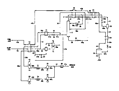
[0014] FIG. 1 illustrates a flow diagram of a process in accordance
with the
present invention adapted to produce an LNG product with a methane purity in
excess
of 99%.
[0015] In the simulation of the FIG. 1 process, inlet gas taken from
a natural
gas transmission pipeline enters the plant at 100 F [38 C] and 900 psia
116,205 kPa(a)1
as stream 30. Stream 30 is cooled in heat exchanger 10 by heat exchange with
cool
LNG flash vapor at -115 F [-82 C1 (stream 43c), cool expanded vapor at -57 F
[-49 C1 (stream 35a), and cool flash vapor and liquid at -115 F [-82 C1
(stream 46).
The cooled stream 30a at -52 F [-47 C1 and 897 psia 116,185 kPa(a)1 is divided
into
two portions, streams 31 and 32. Stream 32, containing about 32% of the inlet
gas,
enters separator 11 where the vapor (stream 33) is separated from the
condensed
liquid (stream 34).
[0016] Vapor stream 33 from separator 11 enters a work expansion
machine
13 in which mechanical energy is extracted from this portion of the high
pressure
feed. The machine 13 expands the vapor substantially isentropically to
slightly above
the operating pressure of LNG purification tower 17, 435 psia 112,999 kPa(a)1,
with the
work expansion cooling the expanded stream 33a to a temperature of
approximately
-108 F [-78 C1. The typical commercially available expanders are capable of
recovering on the order of 80-85% of the work theoretically available in an
ideal
isentropic expansion. The work recovered is often used to drive a centrifugal
compressor (such as item 14), that can be used to compress gases or vapors,
like
-6-

CA 02732046 2011-01-26
WO 2010/017061
PCT/US2009/051901
stream 35b for example. The expanded and partially condensed stream 33a is
divided
into two portions, streams 35 and 36.
[0017] Stream 36, containing about 35% of the effluent from expansion
machine 13, is further cooled in heat exchanger 18 by heat exchange with cold
LNG
flash vapor at -153 F [-103 C] (stream 43b) and cold flash vapor and liquid at
-153 F
[-103 C] (stream 45). The further cooled stream 36a at -140 F [-96 C] is
thereafter
supplied to distillation column 17 at a mid-column feed point. The second
portion,
stream 35, containing the remaining effluent from expansion machine 13, is
directed
to heat exchanger 15 where it is warmed to -57 F [-49 C] as it further cools
the
remaining portion (stream 31) of the cooled stream 30a. The further cooled
stream
31a at -82 F [-64 C] is then flash expanded through an appropriate expansion
device,
such as expansion valve 16, to the operating pressure of fractionation tower
17,
whereupon the expanded stream 31b at -126 F [-88 C] is directed to
fractionation
tower 17 at a lower column feed point.
[0018] Distillation column 17 serves as an LNG purification tower. It
is a
conventional distillation column containing a plurality of vertically spaced
trays, one
or more packed beds, or some combination of trays and packing. This tower
recovers
nearly all of the hydrocarbons heavier than methane present in its feed
streams
(streams 36a and 31b) as its bottom product (stream 38) so that the only
significant
impurity in its overhead (stream 37) is the nitrogen contained in the feed
streams.
Equally important, this tower also captures in its bottom product nearly all
of the
carbon dioxide feeding the tower, so that carbon dioxide does not enter the
downstream LNG cool-down section where the extremely low temperatures would
cause the formation of solid carbon dioxide, creating operating problems.
Stripping
-7-

CA 02732046 2011-01-26
WO 2010/017061
PCT/US2009/051901
vapors for the lower section of LNG purification tower 17 are provided by the
vapor
portion of stream 31b, which strips some of the methane from the liquids
flowing
down the column.
[0019] Reflux for distillation column 17 is created by cooling and
condensing
the tower overhead vapor (stream 37 at -143 F [-97 C1) in heat exchanger 18 by
heat
exchange with streams 43b and 45 as described previously. The condensed stream

37a, now at -148 F 11-100 C1, is divided into two portions. One portion
(stream 40)
becomes the feed to the LNG cool-down section. The other portion (stream 39)
enters
reflux pump 19. After pumping, stream 39a at -148 F 11-100 C1 is supplied to
LNG
purification tower 17 at a top feed point to provide the reflux liquid for the
tower.
This reflux liquid rectifies the vapors rising up the tower so that the tower
overhead
vapor (stream 37) and consequently feed stream 40 to the LNG cool-down section

contain minimal amounts of carbon dioxide and hydrocarbons heavier than
methane.
[0020] The feed stream for the LNG cool-down section (condensed
liquid
stream 40) enters heat exchanger 51 at -148 F [-100 C1 and is subcooled by
heat
exchange with cold LNG flash vapor at -169 F [-112 C1 (stream 43a) and cold
flash
vapor at -164 F [-109 C1 (stream 41). Subcooled stream 40a -150 F [-101 C1
from
heat exchanger 51 is flash expanded through an appropriate expansion device,
such as
expansion valve 52, to a pressure of approximately 304 psia 112,096 kPa(a)1.
During
expansion a portion of the stream is vaporized, resulting in cooling of the
total stream
to -164 F [-109 C1 (stream 40b). The flash expanded stream 40b enters
separator 53
where the flash vapor (stream 41) is separated from the liquid (stream 42).
The flash
vapor (first flash vapor stream 41) is heated to -153 F [-103 C1 (stream 41a)
in heat
exchanger 51 as described previously.
-8-

CA 02732046 2011-01-26
WO 2010/017061
PCT/US2009/051901
[0021] Liquid stream 42 from separator 53 is subcooled in heat
exchanger 54
to -168 F [-111 C1 (stream 42a). Subcooled stream 42a is flash expanded
through an
appropriate expansion device, such as expansion valve 55, to the LNG storage
pressure (90 psia 11621 kPa(a)1). During expansion a portion of the stream is
vaporized, resulting in cooling of the total stream to -211 F 11-135 C1
(stream 42b),
whereupon it is then directed to LNG storage tank 56 where the LNG flash vapor

resulting from expansion (stream 43) is separated from the LNG product (stream
44).
The LNG flash vapor (second flash vapor stream 43) is then heated to -169 F
[-112 C1 (stream 43a) as it subcools stream 42 in heat exchanger 54. Cold LNG
flash
vapor stream 43a is thereafter heated in heat exchangers 51, 18, and 10 as
described
previously, whereupon stream 43d at 95 F [35 C] can then be used as part of
the fuel
gas for the plant.
[0022] Tower bottoms stream 38 from LNG purification tower 17 is
flash
expanded to the pressure of cold flash vapor stream 41a by expansion valve 20.

During expansion a portion of the stream is vaporized, resulting in cooling of
the total
stream from -133 F [-92 C1 to -152 F [-102 C1 (stream 38a). The flash expanded

stream 38a is then combined with cold flash vapor stream 41a leaving heat
exchanger
51 to form a combined flash vapor and liquid stream (stream 45) at -153 F [-
103 C1
which is supplied to heat exchanger 18. It is heated to -119 F [-84 C1 (stream
45a) as
it supplies cooling to expanded stream 36 and tower overhead vapor stream 37
as
described previously.
[0023] The liquid (stream 34) from separator 11 is flash expanded to
the
pressure of stream 45a by expansion valve 12, cooling stream 34a to -102 F [-
74 C1.
The expanded stream 34a is combined with heated flash vapor and liquid stream
45a
-9-

CA 02732046 2011-01-26
WO 2010/017061
PCT/US2009/051901
to form cool flash vapor and liquid stream 46, which is heated to 94 F 1135 C1
in heat
exchanger 10 as described previously. The heated stream 46a is then re-
compressed
in two stages, compressor 23 and compressor 25 driven by supplemental power
sources, with cooling to 120 F 1149 C1 between stages supplied by cooler 24,
to form
the compressed first residue gas (stream 46d).
[0024] The heated expanded vapor (stream 35b) at 95 F 1135 C1 from
heat
exchanger 10 is the second residue gas. It is re-compressed in two stages,
compressor
14 driven by expansion machine 13 and compressor 22 driven by a supplemental
power source, with cooling to 120 F 1149 C1 between stages supplied by cooler
21.
The compressed second residue gas (stream 35e) combines with the compressed
first
residue gas (stream 46d) to form residue gas stream 47. After cooling to 120 F

1149 C1 in discharge cooler 26, the residue gas product (stream 47a) returns
to the
natural gas transmission pipeline at 900 psia 116,205 kPa(a)l.
[0025] A summary of stream flow rates and energy consumption for the
process illustrated in FIG. 1 is set forth in the following table:
-10-

CA 02732046 2011-01-26
WO 2010/017061 PCT/US2009/051901
Table I
(FIG. 1)
Stream Flow Summary - Lb. Moles/Hr [kg moles/Hr]
Stream Methane Ethane Propane Butanes+ C. Dioxide
Total
30 1,178 69 27 25 8 1,318
31 371 22 9 8 2 415
32 807 47 18 17 6 903
33 758 36 10 4 5 820
34 49 11 8 13 1 83
35 493 24 7 3 3 533
36 265 12 3 1 2 287
37 270 0 0 0 0 277
38 474 34 12 9 4 536
39 108 0 0 0 0 111
40 162 0 0 0 0 166
41 20 0 0 0 0 21
42 142 0 0 0 0 145
43 32 0 0 0 0 35
45 494 34 12 9 4 557
46 543 45 20 22 5 640
47 1,036 69 27 25 8 1,173
44 110 0 0 0 0 110
-11-

CA 02732046 2011-01-26
WO 2010/017061 PCT/US2009/051901
Recoveries*
LNG 13,389 gallons/D [ 111.7 m3/D]
1,781 Lbs/H [ 1,781 kg/111
LNG Purity 99.35%
Power
1st Residue Gas Compression 428 HP l 704 kW]
2nd Residue Gas Compression 145 HP l 238 kW]
Totals 573 HP l 942 kW]
* (Based on un-rounded flow rates)
[0026] The total compression power for the FIG. 1 embodiment of the
present
invention is 573 HP 11942 kW], producing 13,389 gallons/D [111.7 m3/D1 of LNG.

Since the density of LNG varies considerably depending on its storage
conditions, it is
more consistent to evaluate the power consumption per unit mass of LNG. For
the
FIG. 1 embodiment of the present invention, the specific power consumption is
0.322 HP-H/Lb 110.529 kW-H/kg], which is similar to that of comparable prior
art
processes. However, the present invention does not require carbon dioxide
removal
from the feed gas prior to entering the LNG production section like most prior
art
processes do, eliminating the capital cost and operating cost associated with
constructing and operating the gas treatment processes required for such
processes.
[0027] In addition, the present invention produces LNG of higher
purity than
most prior art processes due to the inclusion of LNG purification tower 17.
The
purity of the LNG is in fact limited only by the concentration of gases more
volatile
than methane (nitrogen, for instance) present in feed stream 30, as the
operating
-12-

CA 02732046 2011-01-26
WO 2010/017061
PCT/US2009/051901
parameters of LNG purification tower 17 can be adjusted as needed to keep the
concentration of heavier hydrocarbons in the LNG product as low as desired.
Other Embodiments
[0028] Some circumstances may favor splitting the feed stream prior
to
cooling in heat exchanger 10. Such an embodiment of the present invention is
shown
in FIG. 2, where feed stream 30 is divided into two portions, streams 31 and
32,
whereupon streams 31 and 32 are thereafter cooled in heat exchanger 10.
[0029] In accordance with this invention, external refrigeration may
be
employed to supplement the cooling available to the feed gas from other
process
streams, particularly in the case of a feed gas richer than that described
earlier. The
particular arrangement of heat exchangers for feed gas cooling must be
evaluated for
each particular application, as well as the choice of process streams for
specific heat
exchange services.
[0030] It will also be recognized that the relative amount of the
feed stream 30
that is directed to the LNG cool-down section (stream 40) will depend on
several
factors, including feed gas pressure, feed gas composition, the amount of heat
which
can economically be extracted from the feed, and the quantity of horsepower
available. More feed to the LNG cool-down section may increase LNG production
while decreasing the purity of the LNG (stream 44) because of the
corresponding
decrease in reflux (stream 39) to LNG purification tower 17.
[0031] Subcooling of liquid stream 42 in heat exchanger 54 reduces
the
quantity of LNG flash vapor (stream 43) generated during expansion of the
stream to
the operating pressure of LNG storage tank 56. This generally reduces the
specific
power consumption for producing the LNG by keeping the flow rate of stream 43
low
-13-

CA 02732046 2011-01-26
WO 2010/017061
PCT/US2009/051901
enough that it can be consumed as part of the plant fuel gas, eliminating any
power
consumption for compression of the LNG flash gas. However, some circumstances
may favor elimination of heat exchanger 54 (shown dashed in FIGS. 1 and 2) due
to
higher plant fuel consumption than is typical, or because compression of the
LNG
flash gas is more economical. Similarly, elimination of the intermediate flash
stage
(expansion valve 52 and separator 53, and optionally heat exchanger 51, shown
dashed in FIGS. 1 and 2) may be favored in some circumstances, with the
resultant
increase in the quantity of LNG flash vapor (stream 43) generated, which could
in
turn increase the specific power consumption for the process. In such cases,
expanded liquid stream 38a is directed to heat exchanger 18 (illustrated as
stream 45),
stream 40a is directed to expansion valve 55 (illustrated as stream 42a), and
expanded
stream 42b is thereafter separated to produce flash vapor stream 43 and LNG
product
stream 44.
[0032] In FIGS. 1 and 2, multiple heat exchanger services have been
shown to
be combined in common heat exchangers 10, 18, and 51. It may be desirable in
some
instances to use individual heat exchangers for each service, or to split a
heat
exchange service into multiple exchangers. (The decision as to whether to
combine
heat exchange services or to use more than one heat exchanger for the
indicated
service will depend on a number of factors including, but not limited to, LNG
flow
rate, heat exchanger size, stream temperatures, etc.)
[0033] Although individual stream expansion is depicted in particular
expansion devices, alternative expansion means may be employed where
appropriate.
For example, conditions may warrant work expansion of the further cooled
portion of
the feed stream (stream 31a in FIG. 1 or stream 31b in FIG. 2), the LNG
purification
tower bottoms stream (stream 38 in FIGS. 1 and 2), and/or the subcooled liquid
-14-

CA 02732046 2014-07-29
WO 2010/017061
PCT1US2009/051901
streams in the LNG cool-down section (streams 40a and/or 42a in FIGS. 1 and
2).
Further, isenthalpic flash expansion may be used in lieu of work expansion for
vapor
stream 33 in FIGS. 1 and 2 (with the resultant increase in the power
consumption for
compression of the second residue gas).
[0034] While there have been described what are believed to be
preferred
embodiments of the invention, those skilled in the art will recognize that
other and
further modifications may be made thereto, e.g. to adapt the invention to
various
conditions, types of feed, or other requirements.
-15-

Representative Drawing
A single figure which represents the drawing illustrating the invention.
Administrative Status

For a clearer understanding of the status of the application/patent presented on this page, the site Disclaimer , as well as the definitions for Patent , Administrative Status , Maintenance Fee  and Payment History  should be consulted.

Administrative Status

Title Date
Forecasted Issue Date 2015-02-10
(86) PCT Filing Date 2009-07-28
(87) PCT Publication Date 2010-02-11
(85) National Entry 2011-01-26
Examination Requested 2014-01-16
(45) Issued 2015-02-10
Deemed Expired 2021-07-28

Abandonment History

There is no abandonment history.

Payment History

Fee Type Anniversary Year Due Date Amount Paid Paid Date
Application Fee $400.00 2011-01-26
Maintenance Fee - Application - New Act 2 2011-07-28 $100.00 2011-07-08
Maintenance Fee - Application - New Act 3 2012-07-30 $100.00 2012-07-25
Maintenance Fee - Application - New Act 4 2013-07-29 $100.00 2013-07-04
Request for Examination $800.00 2014-01-16
Maintenance Fee - Application - New Act 5 2014-07-28 $200.00 2014-07-10
Final Fee $300.00 2014-11-10
Maintenance Fee - Patent - New Act 6 2015-07-28 $200.00 2015-07-27
Maintenance Fee - Patent - New Act 7 2016-07-28 $200.00 2016-07-25
Maintenance Fee - Patent - New Act 8 2017-07-28 $200.00 2017-07-24
Maintenance Fee - Patent - New Act 9 2018-07-30 $200.00 2018-07-23
Maintenance Fee - Patent - New Act 10 2019-07-29 $250.00 2019-07-19
Maintenance Fee - Patent - New Act 11 2020-07-28 $250.00 2020-07-15
Owners on Record

Note: Records showing the ownership history in alphabetical order.

Current Owners on Record
ORTLOFF ENGINEERS, LTD.
Past Owners on Record
None
Past Owners that do not appear in the "Owners on Record" listing will appear in other documentation within the application.
Documents

To view selected files, please enter reCAPTCHA code :


To view images, click a link in the Document Description column. To download the documents, select one or more checkboxes in the first column and then click the "Download Selected in PDF format (Zip Archive)" or the "Download Selected as Single PDF" button.

List of published and non-published patent-specific documents on the CPD .

If you have any difficulty accessing content, you can call the Client Service Centre at 1-866-997-1936 or send them an e-mail at CIPO Client Service Centre.


Document
Description 
Date
(yyyy-mm-dd) 
Number of pages   Size of Image (KB) 
Abstract 2011-01-26 1 68
Claims 2011-01-26 23 719
Drawings 2011-01-26 2 46
Description 2011-01-26 15 496
Representative Drawing 2011-01-26 1 21
Representative Drawing 2011-03-24 1 13
Cover Page 2011-03-24 2 53
Claims 2014-01-16 17 768
Description 2014-07-29 15 490
Representative Drawing 2015-01-23 1 11
Cover Page 2015-01-23 1 46
PCT 2011-01-26 2 93
Assignment 2011-01-26 4 82
Prosecution-Amendment 2014-01-16 43 1,720
Prosecution-Amendment 2014-01-16 2 52
Prosecution-Amendment 2014-02-06 2 56
Correspondence 2014-02-12 1 12
Prosecution-Amendment 2014-02-14 2 70
Prosecution-Amendment 2014-07-29 4 97
Correspondence 2014-11-10 2 51