Note: Descriptions are shown in the official language in which they were submitted.
CA 02732075 2011-01-26
WO 2010/017859 - I PCT/EP2009/004450
Description
Indexable cutting insert
Background of the invention
The present invention relates to an indexable cutting
insert, an insert seat for an indexable cutting insert
and a cutting tool having an insert seat and an indexable
cutting insert.
Such indexable cutting inserts can be of one-sided or
double-sided design. In a one-sided indexable cutting
insert, as is known, for example, from WO 2007/127109 Al,
a main face of the indexable cutting insert is configured
as a working surface. The working surface has a plurality
of cutting edges at its rim. If the effective cutting
edge has become worn after a predetermined number of
machining operations, the cutting insert is rotated in
the insert seat, such that the next lip is used. Such
indexable cutting inserts can be designed to be, for
example, triangular, square or hexagonal and then
correspondingly have three, four or six lips, which are
used one after the other.
As a further embodiment, double-sided indexable cutting
inserts are known, for example from WO 2007/037733 Al. In
these indexable cutting inserts, both insert surfaces are
designed as working surfaces and each have cutting edges
at their rims. During the machining, first of all the one
working surface forms the active machining surface, while
the surface facing away from this machining surface is
inactive and rests on the supporting surface of the
insert seat. First of all, in these indexable cutting
inserts, the cutting edges of the active machining
surface become worn one after the other as in a one-sided
indexable cutting insert. If the lips of the active
CA 02732075 2011-01-26
WO 2010/017859 - 2 - PCT/EP2009/004450
machining surface have become worn, the indexable cutting
insert is rotated by 180 in the insert seat, such that
the worn machining surface rests on the supporting
surface and the inactive surface resting previously on
the supporting surface becomes the active machining
surface. The cutting edges of this active machining
surface also become worn one after the- other.
Finally, a further double-sided indexable cutting insert
is known from WO 2007/104275 Al. This cutting insert has
a lip rim having a positive rake angle, said lip rim
adjoining the cutting edge. Adjoining the lip rim is a
falling surface which extends conically about the central
through-hole. The advantage of this indexable cutting
insert lies in the fact that inaccuracies when tightening
the fastening bolt can be compensated for by the conical
region.
Technical problem and object of the invention
With such double-sided indexable cutting inserts there is
the problem of configuring the insert seat in such a way
that the indexable cutting insert rests securely and
fixedly in the insert seat and can be securely clamped
there, but without damaging the cutting edges facing the
supporting surface or those regions of the inactive
working surface of the indexable cutting insert which are
near the lip, said working surface facing thee-supporting
surface of the insert seat. In particular, it is
desirable to be as free as possible with regard to the
configuration of the geometry of the cutting edges and of
the chip breakers.
The object of the present invention is therefore to
design an indexable cutting insert which can be
positioned and clamped in the insert seat in an effective
and dimensionally accurate manner and whose lip geometry
CA 02732075 2011-01-26
WO 2010/017859 - 3 - PCT/EP2009/004450
and whose regions near the lip can be designed as freely
as possible and so as to be adapted to the respective
application. This object is achieved by the combination
of features in claim 1. The combination of features in
claim 12 specifies a correspondingly configured insert
seat. Claim 15 is directed to a corresponding cutting
tool as a whole. The claims that refer back contain
partly advantageous developments of the invention and
partly developments of the invention that are inventive
on their own.
Achievement of the object
The indexable cutting insert according to the invention
first of all has a circumferential lip rim. A cutting
edge is formed on the lip rim. In addition, the lip rim
can have chip breakers or similar cutting aids.
A hollow is provided inside the circumferential lip rim.
This hollow is provided with a number of segment-like
molded bodies corresponding to the number of the
different cutting positions of a working surface.
Finally, a through-hole passes through the working
surface. A fastening bolt, preferably a fastening screw,
with which the indexable cutting insert can be fixed and
clamped to the tool in the insert seat, can be inserted
into the through-hole. The indexable cutting insert
according to the invention has two working surfaces,
facing away from one another, of the type mentioned at
the beginning on the main faces of its parent body.
The molded bodies can be designed, on the one hand, as
hollow bodies, that is to say as recesses, and, on the
other hand, as solids, that is to say as projections.
They thus form a negative or positive relief.
Corresponding molded body receptacles designed to be at
least partly complementary to the molded bodies must be
CA 02732075 2011-01-26
WO 2010/017859 - 4 - PCT/EP2009/004450
provided on the insert seat. For example, it is possible
to configure the molded bodies as prismatic projections.
It then suffices to provide corresponding walls on the
insert seat, and side walls of the prismatic projections
bear against said walls in order to securely position the
indexable cutting insert in its respective cutting
position. The molded bodies then serve solely for the
positioning and as a supporting surface of the indexable
cutting insert, such that the actual lips can be designed
completely independently of these positioning aids.
It is advantageous for each of the molded bodies to be of
identical configuration and to attach them like a relief
ring to the surface of the hollow. In this way, the
molded bodies arranged next to one another form a
structure like a spur gear which has a constant pitch. If
a molded body adjacent to a molded body in engagement
with the molded body receptacle is brought into
engagement with the molded body receptacle, the indexable
cutting insert is indexed, as it were, by one pitch
interval and thus the next lip is activated.
As already stated, it is possible with the invention to
provide chip breakers or similar cutting aids in the
region of the lip rim. For example, a ring consisting of
a CBN or PCD cutting material can be brazed or adhesively
bonded in place as a cutting aid. The possibility of also
providing the indexable cutting insert with two
differently configured working surfaces is especially
advantageous, such that various cutting tasks or, for
example, a rough machining operation and a subsequent
finish machining operation can be realized with the same
indexable cutting insert.
Description of the figures
The invention is explained in more detail with reference
CA 02732075 2011-01-26
WO 2010/017859 - 5 - PCT/EP2009/004450
to the exemplary embodiment shown in the figures. In the
drawing:
fig. 1 shows the plan view of a working surface of an
indexable cutting insert according to the
invention,
fig. 2 shows the perspective view of the indexable
cutting insert shown in fig. 1,
fig. 3 shows a sectional view through the circumference
of the indexable cutting insert shown in fig. 1,
fig. 4 shows a view of the insert seat,
fig. 5a shows an indexable cutting insert resting in the
insert seat,
fig. 5b shows the section V-V in fig. 5a,
fig. 6a shows an indexable cutting insert resting in an
insert seat,
fig. 6b shows the section VI-VI from fig. 6a,
fig. 7a shows an indexable cutting insert resting in the
insert seat,
fig. 7b shows the section VII-VII shown in fig. 7a,
fig. 8 shows a sectional illustration of a first
embodiment of an indexable cutting insert resting
in the insert seat,
fig. 9 shows a sectional illustration of a second
embodiment of an indexable cutting insert resting
in the insert seat.
Description of the exemplary embodiment
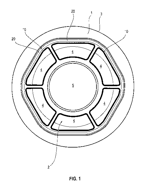
The indexable cutting insert shown greatly enlarged in
fig. 1 has first of all the circumferential lip rim 1 and
a hollow 2. In the exemplary embodiment, the lip rim 1 is
defined by a virtually circular line which forms a
circumferential cutting edge 3. Six trapezoidal molded
bodies 4 are provided next to one another like a relief
in the hollow 2. The molded bodies 4 are exactly the same
size and project from the hollow 2. As a result of their
CA 02732075 2011-01-26
WO 2010/017859 - 6 - PCT/EP2009/004450
constant pitch, the molded bodies 4 form indexing for the
indexable cutting insert in the insert seat. Chip
breakers of various configuration or, for example, a ring
of CBN or PCD cutting material that is adhesively bonded
or brazed in place can be provided as a cutting aid in
the region of the lip rim 1.
The through-hole 5 passing through the parent body of the
cutting insert can be seen especially clearly in fig. 2.
The through-hole 5 extends concentrically to its center
line 22, which can be seen in the illustration in fig. 3.
In the final fitted state of the indexable cutting
insert, a fastening bolt preferably configured as
fastening screw 6 is pushed through the through-hole 5
for fixing the indexable cutting insert in the insert
seat. The fastening screw 6 then runs concentrically to
the center line 22 of the through-hole 5. In the
exemplary embodiment, the flat surfaces of the molded
bodies 4 are arranged in one plane and extend at an angle
of 90 to the center line 22 of the through-hole 5.
It can be seen in the exemplary embodiment that the
indexable cutting insert is configured as a cylindrical
body, but this need not necessarily be the case. Here,
the two top surfaces of the cylinder are configured as
working surfaces. The working surface resting on the
supporting surface 7 of the insert seat forms the
inactive positioning surface 8 of the indexable cutting
insert. The machining surface 9 faces diametrically away
from this positioning surface 8 of the indexable cutting
insert. During the cutting operation, the machining
surface 9 is in engagement with the workpiece, while the
indexable cutting insert rests with the positioning
surface 8 on the supporting surface 7 of the tool seat.
The use of the molded bodies 4 may be explained with
CA 02732075 2011-01-26
WO 2010/017859 - 7 - PCT/EP2009/004450
reference to fig. 1. In the illustration in fig. 1, this
is to be explained with reference to the molded body 4 in
the "two o'clock position" and to the molded body 4 in
the "ten o'clock position" opposite the molded body 4 in
the "two o'clock position". The molded bodies 4 are of
roughly trapezoidal configuration with a long trapezoid
side effective as bearing strip 10. The bearing strip 10
is in, each case depicted as reference sign only on the
molded bodies 4 explained here in the "two o'clock
position" and "ten o'clock position", respectively.
The section VI-VI through the bearing strip 10 of the
molded body 4 in the "two o'clock position" or "ten
o'clock position" is shown in fig. 6a. In fig. 6b,
firstly the supporting surface 7 on the insert seat for
the indexable cutting insert is shown. The supporting
surface 7 is defined in each case by stop edges 12.
Either the bearing strips 10 (fig. 9) or the bearing
surfaces 20 (fig. 8) bear against these stop edges 12 in
the insert seat and therefore secure the indexable
cutting insert against rotation and also form the
indexing for the indexable cutting insert.
To activate the next part of the cutting edge 3 in each
case, the bearing surface 20 of the molded body 4
adjacent to the respectively active molded body 4 is
brought into engagement with the mating bearing surface
12. This ensures that the respectively active region of
the cutting edge 3 always has the same relative position
relative to the insert seat and thus also relative to the
workpiece during the machining.
In the section shown in fig. 6a and fig. 6b, the
effective stop edges 12 of the insert seat are situated
well inside the insert seat with respect to the tool.
Fig. 7a and fig. 7b show a section with stop edges 12
CA 02732075 2011-01-26
WO 2010/017859 - 8 - PCT/EP2009/004450
which are arranged well to the outside on the tool with
respect to the body of the tool. The section VII-VII runs
through the bearing strip 10 of the molded body 4 or
through the bearing surface 20 of the indexable cutting
insert in the "four o'clock position" or "eight o'clock
position". The insert seat again has the supporting
surface 7 with the stop edges 12. Either the bearing
strips 10 (fig. 9) or the stop surfaces 20 (fig. 8) bear
against these stop edges 12. In addition to the
supporting surface 7, a clearance portion 18 for
accommodating the cutting edge 3 of the indexable cutting
insert can be seen on the insert seat in both fig. 6b and
fig. 7b.
The machining surface 9 of the indexable cutting insert
is tilted relative to the center longitudinal axis 13 of
the tool in a preferred embodiment. In this case, the
axial angle 14 of the machining surface 9 relative to the
center longitudinal axis 13 is of the order of magnitude
of 3 to 10 . A tilt angle 14 of 7 is especially
preferred. The fastening screw 6 has a screw-in angle 16
within the range of 0 to 10 , preferably 8 , relative to
the normal 15 of the center longitudinal axis 13.
The position angle 17 of the insert seat relative to the
center longitudinal axis 13 is within the range of 10 to
50 , preferably 30 .
Fig. 8 shows a sectional illustration of a first
exemplary embodiment of an indexable cutting insert
according to the invention resting in the insert seat.
The positioning surface 8 and the machining surface 9 of
the indexable cutting insert shown in fig. 8 are designed
to be identical, for which reason the reference numerals
applicable to both surfaces are only marked on the
machining surface 9 for the sake of better readability.
CA 02732075 2011-01-26
WO 2010/017859 - 9 - PCT/EP2009/004450
It can be seen from the illustration in fig. 8 that the
indexable cutting insert, with its hollow 2, completely
bridges that region of the supporting surface 7 which
runs horizontally in fig. 8. Consequently, with its
bearing surfaces 20, which run obliquely from the lip rim
1 in the direction of the hollow 2, the indexable cutting
insert bears against that region of the supporting
surface 7 which runs out into the clearance portions 18.
In this embodiment shown in fig. 8, the lip rim is
preferably configured as a chip breaker.
Fig. 9 shows a second exemplary embodiment in which a
relief-like projection 21 is provided in the hollow 2.
The relief-like projection 21 has the bearing strips 10
on the indexable cutting insert on its obliquely running
side ends. The supporting surface 7 in the insert seat is
of bowl-like configuration, such that the projection 21
rising from the positioning surface 8 can engage in the
supporting surface 7 of bowl-like configuration. The
bearing strips 10 of the indexable cutting insert then
bear against the stop edges 12 which form the rims of the
bowl-like supporting surface 7.
A plurality of fixing variants are possible with the
indexable cutting insert according to the invention. In a
first variant (fig. 8), the positioning surface 8 of the
indexable cutting insert covers the entire supporting
surface 7 of the insert seat, such that the indexable
cutting insert bears with its bearing surface 20 against
the stop edges 12 of the insert seat. In a second variant
(fig. 9), the positioning surface 8 of the indexable
cutting insert only partly covers the supporting surface
7 of the insert seat, and the bearing strip 10 of the
molded body 4 of the indexable cutting insert bears
against the associated stop edge 12 of the insert seat.
These two aforementioned variants can each be combined
CA 02732075 2011-01-26
WO 2010/017859 - 10 - PCT/EP2009/004450
with two different insert seat variants: in the first
insert seat variant (fig. 6a/fig. 6b), the molded bodies
4 (fig. 9) or the associated bearing surfaces 20 (fig. 8)
of the indexable cutting insert which are arranged, in
the final fitted state, in the "two o'clock position", on
the one hand, and in the "ten o'clock position", on the
other hand, are active for the fixing. Here, the stop
strips 10 and bearing surfaces 20, respectively, in the
"two o'clock position" and at the same time in the "ten
o'clock position" are active. This is the embodiment with
fixing of the indexable cutting insert that is effective
well inside the tool body. The second insert seat variant
relates to fixing of the indexable cutting insert that is
arranged well to the outside with respect to the tool
body. Here (fig. 7a/fig. 7b), the molded bodies 4 (fig.
9) or the associated bearing surfaces 20 (fig. 8) of the
indexable cutting insert which are arranged, in the final
fitted state, in the "four o'clock position" and in the
"eight o'clock position" are active. With the indexable
cutting insert according to the invention, therefore, a
comparatively large number of insert seat configurations
of the indexable cutting inserts can be realized, such
that a high degree of flexibility is ensured with regard
to the application.