Note: Descriptions are shown in the official language in which they were submitted.
CA 02732143 2011-01-18
WO 2010/038148 PCT/IB2009/007029
REAR DRIVE MODULE WHEEL DISCONNECT
TECHNICAL FIELD
[0001] The present invention relates to a wheel disconnect system, including a
rear
drive module wheel disconnect system including an integrated constant velocity
(CV) joint.
BACKGROUND
[0002] A conventional AWD driveline for a motor vehicle may include a primary
front
drive axle coupled to a secondary or auxiliary rear drive axle. When the
driveline is
operating in a 4X2 mode of operation (i.e., four wheels, with two of them
operating as
driving wheels), the primary front drive axle must provide tractive forces not
only to keep the
motor vehicle moving, but also to overcome the frictional losses of the
secondary or auxiliary
rear drive axle that is being driven through the tire/road surface interface.
Driveline losses
may be due to oil churning losses, viscous drag, inertia, as well as friction.
[0003] In an effort to minimize loss and provide a more fuel efficient
driveline when in
a 4X2 mode of operation to improve overall fuel economy, it may be desirable
to disconnect
the secondary or auxiliary drive system, including the secondary or auxiliary
rear drive axle
and the rear wheels. Wheel hub disconnects generally may be separate from the
rear
differential housing and positioned close to each wheel, may be integrated
into the rear
differential housing, or may be somewhere in between the wheel and the rear
differential
housing. Accordingly, disconnecting the rear wheels may be accomplished at the
ends of the
wheels or at the output of a rear drive module (RDM).
[0004] A system that disconnects the rear wheels at the ends of the wheels may
be
more conventional and/or typical in motor vehicles, but may also be more
complicated than a
system that disconnects the wheels at the RDM. While a system that disconnects
the wheels
at the RDM may be acceptable since most of the system losses are internal to
the RDM, such
a system may undesirably increase the package size and component count of the
wheel
disconnect system. It may be desirable to provide a wheel disconnect system
that disconnects
- 1-
CA 02732143 2011-01-18
WO 2010/038148 PCT/IB2009/007029
the wheels at the output of the rear drive module, while managing to avoid an
increased
package size and component count.
SUMMARY
[0005] A wheel disconnect system may include a rear drive module and a
constant
velocity joint housing. The rear drive module may include a housing, at least
one actuator at
least partly disposed within the housing, and at least one dog clutch
configured to be
activated by the actuator. The dog clutch may include a first portion
configured to move
when the actuator is moved and a second portion configured for engagement with
the first
portion. The constant velocity joint housing maybe formed integrally with the
second
portion of the dog clutch. A wheel may be disconnected from the rear drive
module unless
engagement of the first portion and the second portion of the dog clutch
allows torque to be
transferred to the wheel.
[0006] In an embodiment, a wheel disconnect system may include a rear drive
module
and a constant velocity joint housing. The rear drive module may include a
housing defining
a cavity configured to be in communication with a source of hydraulic fluid
pressure, at least
one piston disposed in the cavity, and at least one dog clutch configured to
be activated by the
piston. The piston may be configured to move when the hydraulic fluid pressure
is increased.
The dog clutch may include a first portion configured to move when the piston
is moved and
a second portion configured for engagement with the first portion. The
constant velocity
joint housing may be formed integrally with the second portion of the dog
clutch. A wheel
may be disconnected from the rear drive module unless engagement of the first
portion and
the second portion of the dog clutch allows torque to be transferred to the
wheel.
[0007] In another embodiment, a wheel disconnect system may include a rear
drive
module and a constant velocity joint housing. The rear drive module may
include a housing,
at least one electromagnetic actuator at least partly disposed within the
housing, and at least
one dog clutch configured to be activated by the electromagnetic actuator. The
electromagnetic actuator may include at least one ball, an armature plate
proximate at least
one ball, and a coil configured to move the armature plate and at least one
ball when
- 2-
CA 02732143 2011-01-18
WO 2010/038148 PCT/IB2009/007029
activated. The dog clutch may include a first portion configured to move when
the balls and
armature plate are moved and a second portion configured for engagement with
the first
portion. The constant velocity joint housing may be formed integrally with the
second
portion of the dog clutch. A wheel may be disconnected from the rear drive
module unless
engagement of the first portion and the second portion of the dog clutch
allows torque to be
transferred to the wheel.
[0008] A vehicle driveline including a wheel disconnect system is also
provided. The
vehicle driveline may include a rear drive axle; at least one wheel; at least
one rear half shaft
for distributing torque to the at least one wheel; and a wheel disconnect
system. The wheel
disconnect system may include a rear drive module and a constant velocity
joint housing.
The rear drive module may include a housing, at least one actuator at least
partly disposed
within the housing, and at least one dog clutch configured to be activated by
the actuator.
The dog clutch may include a first portion configured to move when the
actuator is moved
and a second portion configured for engagement with the first portion. The
constant velocity
joint housing may be formed integrally with the second portion of the dog
clutch. A wheel
may be disconnected from the rear drive module unless engagement of the first
portion and
the second portion of the dog clutch allows torque to be transferred to the
wheel.
BRIEF DESCRIPTION OF THE DRAWINGS
[0009] Embodiments of the invention will now be described, by way of example,
with
reference to the accompanying drawings, wherein:
[00010] FIG. 1 illustrates an AWD vehicle driveline including a wheel
disconnect
system according to an embodiment of the present invention;
[00011] FIG. 2 is a cross-sectional view of a wheel disconnect system
according to an
embodiment of the present invention;
[00012] FIG. 3 is a cross-sectional view of a wheel disconnect system
according to an
embodiment of the present invention.
- 3-
CA 02732143 2011-01-18
WO 2010/038148 PCT/IB2009/007029
DETAILED DESCRIPTION
[00013] Reference will now be made in detail to embodiments of the present
invention,
examples of which are described herein and illustrated in the accompanying
drawings. While
the invention will be described in conjunction with embodiments, it will be
understood that
they are not intended to limit the invention to these embodiments. On the
contrary, the
invention is intended to cover alternatives, modifications and equivalents,
which may be
included within the spirit and scope of the invention as embodied by the
appended claims.
[00014] Referring to FIG. 1, an AWD vehicle driveline is generally shown. The
AWD
vehicle driveline may comprise a primary drive system and a secondary or
auxiliary drive
system. The primary drive system may comprise a primary front drive axle 10
and one or
more primary drive wheels 12, 14. The secondary or auxiliary drive system may
comprise a
secondary or auxiliary rear drive axle 16 and one or more secondary or
auxiliary drive wheels
18, 20. In an embodiment as illustrated, the primary drive system may include
two primary
drive wheels, and the secondary or auxiliary drive system may include two
auxiliary drive
wheels.
[00015] When the AWD vehicle driveline is operating in a 4X4 mode of operation
(i.e.,
all four wheels transmit power to the road), torque may be transferred from an
engine 22,
through a transmission 24, and into a front driving differential case 26. The
torque may be
further split to a front driving differential 28 and a power transfer unit 30.
The torque that is
split through the front driving differential 28 (e.g., through the front
driving differential gear
set) may then be further distributed via front half shafts 32, 34 to a pair of
primary (e.g.,
front) drive wheels 12, 14 of a motor vehicle. The torque distributed to power
transfer unit
30 may be provided via a hollow shaft 36 that may directly connect the front
driving
differential case 26 to power transfer unit 30. The torque transferred through
the power
transfer unit 30 may drive a drive shaft 38 that in turn drives the rear drive
axle 16.
[00016] Rear drive axle 16 may distribute torque via rear half shafts 40, 42
to a pair of
auxiliary (e.g., rear) drive wheels 18, 20 of the motor vehicle. A wheel
disconnect system 44
may be provided to selectively interrupt torque flow to the auxiliary drive
wheels 18, 20. In
- 4-
CA 02732143 2011-01-18
WO 2010/038148 PCT/IB2009/007029
accordance with an embodiment of the invention, wheel disconnect system 44 may
include a
rear drive module 46 and a constant velocity (CV) joint housing 48.
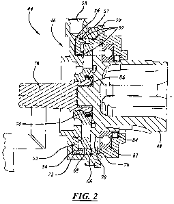
[00017] Referring now to FIG. 2, rear drive module 46 may include a housing
50.
Housing 50 may be provided to at least partially house an actuator 52 disposed
within
housing 50. In a first embodiment of the invention, actuator 52 may comprise
at least one
hydraulic actuation piston 54. In accordance with the first embodiment of the
invention,
housing 50 may define at least one cavity 56 configured to be in communication
with a
source of hydraulic fluid pressure (not shown). The source of hydraulic fluid
pressure may
variably provide fluid pressure to the cavity 56. A hydraulic input and/or
line connection 58
may allow hydraulic fluid from a source of hydraulic fluid to enter cavity 56
of the rear drive
module 46. The rear drive module 46 may include at least two cavities 56 in an
exemplary
embodiment. A separate hydraulic input and/or line connection 58 may be
utilized for each
of the two cavities 56 in an exemplary embodiment. In another exemplary
embodiment, a
single hydraulic input and/or line connection 58 may be used to input
hydraulic fluid into
both cavities for both wheels. It will be appreciated that the source of
hydraulic pressure is
not limited to any particular hydraulic fluid pressure generating device, and
may include
without limitation, a pump, valves, accumulator, and electronic control unit
(ECU), or any
combination thereof. For example, a pump (not shown) may generate hydraulic
pressure. A
switch or signal from the ECU (not shown) may energize and/or control the
pump. For
example, the ECU may keep an accumulator (e.g., part of the hydraulic system
of a motor
vehicle which absorbs fluctuating fluid delivery, stores fluid at pressure,
and can provide a
rapid flow of fluid under pressure) charged to a select or predetermined
pressure range as
monitored by a pressure switch. For another example, the ECU may directly
pressurize the
rear drive module 46. In another example, the source of hydraulic pressure may
be the
pressurized fluid from an automatic transmission.
[00018] In accordance with the first embodiment of the invention, at least one
piston 54
may be disposed in cavity 56. Piston 54 may be configured to move when the
hydraulic fluid
pressure is increased. Piston 54 may be configured to move axially within
cavity 56. The
rear drive module 46 may include at least two pistons 54 in an exemplary
embodiment (e.g.,
one piston for each rear wheel). Piston 54 may also define at least one pocket
57. Each
- 5-
CA 02732143 2011-01-18
WO 2010/038148 PCT/IB2009/007029
pocket 57 may be configured to receive an o-ring seal 59. In an embodiment,
there may be
an o-ring seal 59 on the inner diameter and outer diameter of the piston 54.
[00019] Referring now to FIG. 3, in a second embodiment of the invention,
actuator 52
may comprise at least one electromagnetic ball ramp actuator. The
electromagnetic ball ramp
actuator may comprise at least one ball 60, an armature plate 62, a coil 64,
and a spring 65.
The electromagnetic ball ramp actuator may function in a conventional manner,
such as
known in the art. The electromagnetic ball ramp actuator may be at least
partly disposed
within the housing 50. Coil 64 may be configured to generate an
electromagnetic field that
may affect a position of the armature plate 62. In particular, the coil 64 may
restrain the
armature plate 62 from moving at the same speed as plate portion 68. Plate
portion 68 may
comprise a first portion of a dog clutch 66 as described in additional detail
below. Both
armature plate 62 and plate portion 68 of dog clutch 66 may each include a
ramp in which
balls 60 may be configured to travel. Because coil 64 may restrain the
armature plate 62
from moving at the same speed as plate 68, balls 60 may be allowed to move up
the ramps in
armature plate 62 and plate portion 68 of the dog clutch 66. The movement of
the balls 60
may move the plate portion 68 of the dog clutch 66 away from armature plate
62, thereby
allowing the dog clutch 66 (e.g., first plate portion 68 and second portion 70
as described in
more detail below) to engage. When the balls 60 are at the end of its travel,
the armature
plate 62 may be spinning and/or rotating at the same speed as plate portion
68. Upon
deenergization of the coil 64, a spring 65 may be configured to act on the
armature plate 62.
The action of the spring 65 may result in a decrease in the total thickness of
the
electromagnetic ball ramp actuator as compared to when the coil 64 is
energized. The rear
drive module 46 may include at least two electromagnetic ball ramp actuators
in an
exemplary embodiment (e.g., one electromagnetic ball ramp actuator for each
rear wheel).
[00020] Actuator 52 may be configured to activate a dog clutch 66. The rear
drive
module 46 may include at least two dog clutches 66 in an exemplary embodiment
(e.g., one
dog clutch for each rear wheel). Referring now to both FIGS. 2 and 3, dog
clutch 66 may
comprise a first portion 68 and a second portion 70. The first portion 68 of
the dog clutch 66
may comprise an axially moveable collar. The axially moveable collar may
include dog
clutch features on its radially inner face. The shape and function of dog
clutch features may
- 6-
CA 02732143 2011-01-18
WO 2010/038148 PCT/IB2009/007029
be as are known in the art. For example, the axially moveable collar may
include projections
that are configured to engage corresponding slots (e.g., slots, grooves,
recesses, receiving
portions) in the second portion 70 of the dog clutch 66.
[00021] The position of the first portion 68 may be configured to be affected
by actuator
52. In accordance with a first embodiment of the invention, the first portion
68 of the dog
clutch 66 may be configured to be activated and/or move when piston 54 is
moved. In this
first embodiment, a bearing 72 may be disposed between the piston 54 and the
first portion
68 of the dog clutch 66 to allow for rotation of the first portion of the dog
clutch 68 relative to
the piston 54. In accordance with a second embodiment of the invention, the
position of the
first portion 68 of the dog clutch 66 may be configured to depend on whether
the coil 64 of
the electromagnetic ball ramp actuator is energized and/or deenergized,
thereby allowing
and/or preventing movement of the balls 60. Movement of balls 60 may then
activate and/or
move the first portion 68 of the dog clutch 66.
[00022] The second portion 70 of the dog clutch may be configured for
engagement
with the first portion 68. In at least the first embodiment, a biasing member
(e.g., a resilient
biasing member) 74, such as a compression spring, may apply a force against
the first portion
68 of the dog clutch 66 in a direction away from engagement of the first
portion of the dog
clutch 66 with the second portion 70 of the dog clutch 66. Although a
compression spring is
mentioned in detail, other biasing members may be utilized in other
embodiments. The
wheel disconnect system 44 may provide for left and right rear wheels 18, 20
and left and
right half shafts 40, 42 to be disconnected from the rear drive module 46 in a
default and/or
nonnal position. To connect rear wheels 18, 20 and/or rear half shafts 40, 42
to the rear drive
module 46 for the AWD feature of the motor vehicle, engagement of the first
and second
portions 68, 70 of the dog clutch 66 may allow torque to be transferred to
each wheel. To
connect rear wheels 18, 20 to the rear drive module 46, the actuator 52 may be
used to affect
movement of the dog clutch 66 such that first and second portions 68, 70 of
the dog clutch
are engaged. Accordingly, the wheel disconnect system 44 may be configured for
selectively
connecting and disconnecting the rear half shafts 40, 42 and rear wheels 18,
20 from the rear
drive module 46 using the actuator 52 and dog clutch 66.
- 7-
CA 02732143 2011-01-18
WO 2010/038148 PCT/IB2009/007029
[00023] The torque distributed to the rear drive module 46 may be provided via
a
differential that facilitates differential rotation between a pair of output
shafts (e.g., a half
shaft 78), for example, as is known in the art. The half shaft 78 may include
splines and may
be in splined engagement with the first portion 68 of the dog clutch 66.
[00024] Wheel disconnect system 44 may include a constant velocity (CV) joint
housing
48 for a CV joint 80. CV joints are provided generally to connect shafts to
drive units and are
common in motor vehicles. CV joints may be located at both ends of the rear
half shafts 40,
42 that connect to the wheels 18, 20 and the rear drive module 46, as
generally shown in FIG.
1. The CV joints 80 may be any of the standard types known in the art,
including but not
limited to a ball joint, such as a six ball joint, an eight ball joint, or a
ten ball joint, a plunging
tripod joint, a cross groove joint, a fixed ball joint, a fixed tripod joint,
or a double offset
joint. The CV joint 80 may include any number of various components, such as a
joint boot
(not shown), that are conventional in the art. The CV joint housing 48 may be
substantially
similar to a conventional CV joint housing known in the art, but the CV joint
housing may be
formed integrally with the second portion 70 of the dog clutch 66. The CV
joint housing and
second portion 70 of the dog clutch 66 may, for example, be a one-piece and/or
monolithic
structure.
[00025] The wheel disconnect system 44 may further include a bearing 82
disposed
between the housing 50 of the rear drive module 46 and the CV joint housing
48. The
bearing 82 may be configured to rotatably support the CV joint housing 48. The
rear drive
module 46 may further comprise a retaining clip 76 in order to retain the
bearing 82. The
retaining clip 76 may be at least partially disposed within the housing 50 of
the rear drive
module 46 or may be integral with the housing 50 of the rear drive module 46.
A seal 84
may also be disposed between the housing 50 of the rear drive module 46 and
the CV joint
housing 48. The seal 84 may be configured to avoid leakage of lubricating oil
from the rear
drive module 46. The wheel disconnect system 44 may also include a bushing
disposed
between the half shaft 78 and the CV joint housing 48. The bushing 86 may be
configured
for dampening noise or friction.
- 8-
CA 02732143 2011-01-18
WO 2010/038148 PCT/IB2009/007029
[00026] A wheel disconnect system in accordance with the present invention may
allow
for selective disconnection and connection of the rear half shafts and wheels
from a rear drive
module. Accordingly, the inventive wheel disconnect system may be configured
to
disconnect the rear half shaft from the rear drive module, rather than at the
wheel ends. By
integrating the CV joint as part of the dog clutch of the rear drive module,
the wheel
disconnect system may be further simplified while reducing package size and
component
count of the wheel disconnect system. For example, a wheel disconnect system
in
accordance with the present invention may not require a viscous coupling which
may result
weight savings. A wheel disconnect system in accordance with the present
invention may
also improve fuel economy by eliminating ring gears and differential viscous
spin losses and
mechanical rotational losses. A wheel disconnect system in accordance with the
present
invention may also be configured for use with existing vehicle mounts with no
required
modification to existing rear half shafts.
[00027] The foregoing descriptions of specific embodiments of the present
invention
have been presented for purposes of illustration and description. They are not
intended to be
exhaustive or to limit the invention to the precise forms disclosed, and
various modifications
and variations are possible in light of the above teaching. The embodiments
were chosen and
described in order to explain the principles of the invention and its
practical application, to
thereby enable others skilled in the art to utilize the invention and various
embodiments with
various modifications as are suited to the particular use contemplated. The
invention has
been described in great detail in the foregoing specification, and it is
believed that various
alterations and modifications of the invention will become apparent to those
skilled in the art
from a reading and understanding of the specification. It is intended that all
such alterations
and modifications are included in the invention, insofar as they come within
the scope of the
appended claims. It is intended that the scope of the invention be defined by
the claims
appended hereto and their equivalents.
- 9-