Note: Descriptions are shown in the official language in which they were submitted.
CA 02732193 2013-01-03
-1-
DEPTH AND WIDTH ADJUSTABLE DISPLAY
TRACK UNIT WITH REMOVABLE PARTMQNS
BACKGROUND OF THE INVENTION
The present invention relates to a display track, and more particularly to a
depth and width adjustable track unit with removable partitions.
Display shelves are commonly found in stores, supermarkets, and the like
for the display of products available for sale. The display shelf may be flat,
in
which case there is typically a spring-loaded pusher unit to push the
displayed
3.0 products forward as each foremost product is purchased and reraoved, or
inclined,
in which case, as each foremost product is removed, the remainder of the
products
move forwardly under the influence of gravity (such shelves typically being
known
as "gravity-feed shelves"). Depending upon the type of products to be
displayed,
the display shelf maybe disposed on a counter or table top (for example, where
the
products for display are batteries, filni, or other dry, canned, boxed or
bagged food
= and consumer products commonly sold at room temperature) or on a
supporting
tray in a refrigeration unit (for example, where the products are bottles or
cans of
beer, soda, milk or other products commonly sold chilled). The display shelf
may
= consist of a *single track or channel but more commonly consists of a
plurality of
such tracks disposed side-by-side in either a find or releasable relationship.
CA 02732193 2011-02-18
-2-
From the point of view of the retailer, the display shelf should be of
sufficient depth (that is, the length from the front thereof to the back
thereof) that
the entire depth of the support surface (i.e., the counter, table top or
refrigeratioa
tray) is occupied by the shelf¨that is, so that there is no wasted space. If
the
display shelf does not occupy the full depth, objects placed on the support
surface
in front of the display shelf will conceal the products intended to be
displayed on
the display shelf, while objects placed on the support surface behind the
display
shelf will be at least partially hidden from customer view and not readily
accessible
to a potential customer. This problem has been addressed in the past by
providing
a "standard depth" shelf which has breakaway rear portions enabling the depth
of
the display shelf to be shortened to meet the available space. An obvious
disadvantage of this solution to the problem is that some counters, tabletops
or
refrigeration trays will be deeper than the "standard depth" display shelves.
Another solution to this problem is to provide the retailer with a "standard
depth" display shelf and add-on sections. The add-on sections may be "added
on"
to the back of the display shelf (assuming that t1ie display shelf does not
have a
back wall which would interfere with the passage of products from the add-on =
sections to the main display shelf). Alternatively, where the front and back
sections of the display shelf may be separated (e.g., broken-away), the add-on
sections may be inserted between the separated front and back sections of the
display shelf.
The "add-on sections" solution is not favored, however, either by the retailer
or the display shelf manufacturer. 'Typically additional members--e.g.,
fasteners or
CA 02732193 2011-02-18
=
-3-
connecters¨must be used to connect the add-on sections either to the back
section
of the display shelf or to the front of the back section and the back of the
front
section of the display shelf. Such connecters are typically relatively small
and easy
to lose during the assembly process. From the point of view of the
manufacturer
of the display shelf, the add-on sections solution is particularly onerous
because the
manufacturer must not only purchase, maintain and operate the usual molds for
the production of the standard depth display shelf, but also a special mold
for the
production of the add-on sections. The add-on sections solution further
entails
logistical problems in that a separate inventory of the add-on sections must
be
maintained by the manufacturer, made available for purchase, and delivered to
purchasers. In brief, the manufacturer must manufacture, sell and deliver two
products¨that is, the standard depth display shelf and the add-on
sections¨rather
than merely One product (that is, the standard depth display shelf).
As a practical matter, the dilemma of the producer is even greater since the
customer may desire add-on sections of different depths so that the customer
can
make full use of the available depths of a variety of different-depth support
surfaces. Each of these add-on sections of differing depth then becomes yet
another product line to be manufactured, sold and delivered by the
manufacturer.
For the various racks, whether enlarged or reduced in the length and width
dimensions, it is typical to utilize a plurality longitudinally extending
partition
which may be installed in selected locations to accommodate products of
various
widths. It is important to provide removable partitions extending lengthwise
on
the display tracks which partitions need to be easily installed and easily
removed
CA 02732193 2011-02-18
. '
-4-
and easily changed in length to match the shape and space in the gondola
display
case.
Further problems with partitions are that products divided by the partitions
nevertheless tend to topple off the front of the display track or in display
cabinets
with front doors, to slide too far and lie against the front door and then
fall out
when the door is open. Also these partitions become clislodged because
customers
pull on products or pull on the partitions themselves when products become
wedged between them.
A further factor is economy of space. Space is at a premium and it is
desirable to have the absolute maximum amount of lateral and depth space and
also height Therefore, the partitions need to be coupled to the tracks while
utilizing a minimum of depth of the track.
Typical prior art partitions have included numerous structural and
functional features which inhibit their usefulness. this usually occurs when
achieving one objective necessitates sacrifice or compromises another. For
example, ease of installation and removal often results in partitions that are
easily
dislodged or are unstable against topping forces. Conversely, highly secure
and
stable partitions are often quite cumbersome to install and remove. Efforts to
solve
these problems have been hindered by various factors inherent in the industry,
including the need to maximize display space, and to incorporate maximum
flexibility to enlarge or reduce display rack dimensions, and to render these
products so user friendly that minimum training is required for installation
and
adjustment.
CA 02732193 2011-02-18
. . a .
-5-
It is an objective for these partitions to be easily installable and
removable,
and to be resistant to dislodgment or tipping, and to be adjustable in length
to
correspond to the length selected for the display rack.
It is a further objective to have the new improvements applicable to various
known display track structures, and particularly to the display track as
disclosed
in the parent application of the present continuation-in-part application.
It is still further objective to design partitions which are readily
installed, are
highly resistant to tipping, shifting or otherwise being dislodged while
installed and
are readily removable without special skills or equipment.
Another object is to provide releasably locking or safety coupling means so
that these partitions cannot be accidentally dislodged by customers when they
take
displayed products or by store operators when they install or adjust these
display
locks.
A further object is to provide a front lip onto the display track to prevent
forward toppling of products.
A still further object is to utilize existing structure of adjacent
longitudinal
support bars of triangular cross-sections to cooperate with partitions to
result in
easy releasable connectability and stability.
Accordingly, it is an object of the present invention to provide a depth-
extendable display track unit enabling a customer to form a depth-extended
display
track.
Another object is to provide such a unit which in one preferred embodiment
consists of at least two essentially identical standard depth display tracks.
CA 02732193 2011-02-18
= =
-6-
A further object is to provide such a unit which in one preferred
embodiment does not require the manufacturer to manufacture, sell or deliver
add-
on sections to enable formation of the depth-extended display track.
It is also an object of the present invention to provide such a unit wherein
in one preferred embodiment depth extension is achievable without the use of
additional components such as fasteners.
It is a further object to provide such a unit which is simple and inexpensive
to manufacture and use.
SUMMARY OF THE INVENTION
It has now been fotuid that the above and related objects of the present
invention are obtained in a depth-extendable and/or width extendible display
track
unit which is adapted to receive one or more partitions with new coupling
elements
for releasable attachment to the display track which has corresponding
structure
to receive the partition coupling elements and to receive other releasable
coupling
elements for longitudinal or depth and transverse or width dimensional changes
in the basic display track unit. The depth-extendable display track unit
consists of
at least two essentially identical standard depth display tracks for forming a
single
depth-extended display track from one of the standard depth display tracks and
at
least one section of another of the standard depth display tracks. Each of the
essentially identical standard depth display tracks comprises a front section,
a
breakaway back section with rear engagement means at the rear thereof, and an
interconnected series of breakaway intermediate sections connecting the front
and
back sections. The intermediate and back sections define at the front of each
such
CA 02732193 2011-02-18
'
. =
-7-
section forward engagement means for engagement with the rear engagement
means at the rear of the back section, the forward engagement means being
exposed for engagement by breaking away of the immediately forward section.
In a preferred embodiment, in each of the essentially identical standard
depth display tracks, the rear engagement means projects rearwardly from the
back
section, and the forward engagement means is configured and dimensioned to
receive therein the rear engagement means. Preferably the forward engagement
means is female in nature, the rear engagement means is male in nature, and
the
forward and rear engagement means cooperatively form a male/female
engagement. Preferably the forward and rear engagement means are disposed
below the level of an. article-supporting surface of the intermediate and back
sections.
Optionally the front section defines at the front thereof stop means for
limiting forward movement of articles on the standard depth display track.
In each of the essentially identical standard depth display tracks, at least
one
of the intermediate sections preferably differs in depth from at least one
other of
the intermediate sections.
This new invention provides an integrally molded display track unit for a
gravity feed display tray where the floor surface of each track unit has no
upstanding side walls but is adapted to hold removable partitions. These
partitions
are releasably engageable to the display track by virtue of having coupling
fmgers
that extend below the top surface of the display tray. The top surface is
defined by
a plurality of laterally spaced apart longitudinal ribs whose top surfaces
define the
CA 02732193 2011-02-18
= =
-8-
product support surface and whose bottom surfaces define the ceiling of a
basement space, this space being further defined by longitudinal side walls
and
transverse front and rear walls. Extending transversely of said longitudinal
ribs is
a plurality of transverse beams spaced apart in said longitudinal direction.
All
these rib, beam and wall components comprise an integrally formed injection
molded display track unit.
This basement comprises structure and space to receive positioning and
releasable locking tabs or fingers that extend from the partitions downward
between pairs of adjacent ribs and engage basement structure below the
ceffing.
In some ern. bodiments, the downward extending fingers from the partitions
engage
the bottom surfaces of transverse beams; in other embodiments these fingers
engage the bottom surfaces of the longitudinal ribs. In all these embodiments
the
fingers cooperate with the basement structure to help position, stabilize and
secure
the partitions with respect to the display tracks, and particularly to prevent
partitions from being lifted or otherwise unintentionally displaced from their
proper position. The basement further provides structure to engage the various
coupling elements for joining display track segments to extend in the
longitudinal
and/or transverse direction.
It is a further object of this invention to provide on the bottom of each
partition a plurality and darts or arrow shaped coupling means which extend
downward between adjacent longitudinal ribs in the display track for
releasably
coupling thereto. In a preferred embodiment these downward extending coupling
CA 02732193 2011-02-18
, = = =
-9-
means extending alternatively left and right and are resilient for easier
installation
and removal.
A further object of the invention is to provide stop means of various heights
at the front of certain partitions to bar packages from falling off the front
edge.
Such stop means may be in the form of: (a) a transverse strip or plate which
extends across the entire front of the display track unit and extends upward
from
the top surface of the track, or (b) a narrow wall segment extending upward to
an
elevation higher than said transverse strip and extending only a short
distance on
one side of the partition or on both sides, the latter called a cathedral
configuration.
A further object of this invention is to provide additional support and
strengthening means for the plurality of display tracks which are coupled
together
in a transverse direction. This strengthening is provided by a transverse beam
extending across and snugly engaging the front walls of ail of the display
track
segments that are joined together side-by-side. A variation of this beam not
only
traverses and engages all the front walls of the joined display track units,
but
extends upward and is called lip extender to serve the additional function of
stopping articles from falling off the front.
Another object of the invention is to include with the releasable coupling
element for the partition, a trigger formed as a resilient portion of the
partition
itself. Pulling the trigger releases a finger from its engagement with a
mating part
of the display track. Preferably such mating part would be a portion of a
transverse
beam in the structure thereof.
CA 02732193 2011-02-18
. '
-10-
A still further object of this invention to arrange for the partition to be
stabilized in its desired location by having a plurality of longitudinally
spaced
fingers each extending forward so that the partition, when installed and slid
forward, cannot be displaced upward by accident unless and until the u.ger
releases
the coupling and pushes the partition rearward to disengage the forward
directed
fingers. Here a trigger release will allow the partition to be slid rearward
and then
lifted upward.
An additional object of this invention to provide below the display track a
basement area which provides space for all the coupling means of the
partitions
and for lateral connection and lengthwise connection means of the respective
display track components. Such basement will provide a strong structure to
support a front lip molded integrally with the display track.
A further object of this invention it to configure the longitudinal ribs to
have
triangular cross-section where the apex of the triangle faces upward and where
the
adjacent sides of adjacent ribs define a generally triangular space pointing
downward. The bottom portion of the partition has a downward pointing
triangular shape whose sides engage the spaced apart sloping sides of the two
triangular ribs. The ribs thus support the partition from extending farther
downward and also stabilize it from tilting or rocking while it is coupled to
these
longitudinal ribs. Coupling is enhanced by a tooth, surface or tab which is
cammed
transversely as the partition is pressed downward, until it snaps under one of
the
longitudinal ribs. It is subsequently releasable by tilting and pulling of the
partition
upward.
CA 02732193 2011-02-18
= *"
-11-
BRIEF DESCRIPTION OF THE DRAWING
The above and related objects, features and advantages of the present
invention will be more fully understood by reference to the following detailed
description of the presently preferred, albeit illustrative, embodiments of
the
present invention when taken in conjunction with the accompanying drawing
wherein:
FIG. 1 is an isometric schematic view of a depth-extendable display track
unit according to the present invention, including two standard depth display
tracks;
FIG. 2 is an exploded isometric view of one of the two standard depth
display tracks of the unit;
FIG. 3 is an isometric schematic view of a depth-extended display track
formed from the unit of FIG. 1 and the left-over remnants of the unit;
FIG. 4 is a top plan semi-schematic view, to an enlarged scale, of a standard
depth display track of the unit
FIG. 5 is a side elevational semi-schematic view, to an enlarged scale,
thereof;
FIG. 6 is a fragmentary isometric view, to a greatly enlarged scale, of a
portion of a standard depth display track of the unit
FIGS. 7 and 8 are fragmentary views, to a further enlarged scale, of the
bracketed segment of FIG.. 3 (identified by the designations of FIGS. 7 and 8)
CA 02732193 2011-02-18
. = 4.
-12-
showing the rear and front engagement means in a separated relationship in
FIG.
7 and in an engaged relationship in FIG. 8;
FIGS. 9 and 10 are sectional views taken along the lines 9-9 of FIGS. 7 and
10-10 of FIG. 8, respectively;
FIGS. 11, 12 and 13 are fragmentary views, to a further enlarged scale, of
the bracketed segment of FIG. 6 showing the lateral connecting means, FIGS. 11
and 12 being fragmentary top plan and sectional side elevational views,
respectively, of the lateral connecting means prior to connection and FIG. 13
being
= a fragmentary sectional side elevational view showing the lateral
connection means
after connection;
FIG. 14 is a fragmentary top, front perspective view of a display cabinet or
gondola containing a plurality of the new display tracks of this invention;
FIG. 15 is a fragmentary top, rear prospective exploded view of a display
track induding removable display track units and a front lip extender;
FIG. 15A is a fragmentary bottom, rear perspective view of a track unit of
Fig. 15;
FIG. 15B is a fragmentary sectional view taken along line 153 - 15B in Fig.
15A;
FIG. 16 is a top plan view of display track unit of Fig. 15;
FIG. 17 is a fragmentary left side elevation view of the display track in
section and of a partition and front lip extender assembled together, taken
along
line 17-17 in Fig. 16;
CA 02732193 2011-02-18
t= ..
-13-
FIG. 18 is a fragmentary sectional view taken along line 18-181n Figure 16
showing the connection of two side-by-side segments of the display track;
FIG. 19 is a bottom front perspective view of a partition;
FIG. 20 is a fragmentary top plan view of a portion of the partition of Figure
6 taken along line 20-20 in Figure 19;
FIG. 21 is a fragmentary top plan view similar to Fig. 20 of the partition,
=
now broken apart;
FIG. 22 is a fragmentary sectional view taken along line 22-22 in Fig. 16
showing the connector of a partition beginning engagement with a display
track;
FIG. 23 similar to Fig. 22 showing the connector fully engaged;
FIG. 24 is a fragmentary sectional view taken along lines 24-24 in Figure 16
showing the connection of the partition into the shelf at a location
longitudinally
displaced from the connection in Figure 23;
FIG. 25 is a fragmentary front and bottom prospective view of a second
embodiment of a partition;
FIG. 26 is a fragmentary side elevation view partially in section showing the
partition of Figure 25 assembled with the shelf of Figure 14;
FIG. 26A is similar to FIG. 26,but show a further embodiment of the
partition and display track;
PIG. 27 is a fragmentary left side elevation view of a display track in a
cabinet;
FIG. 28 is a fragmentary side elevation view similar to Fig. 17 showing a
further embodiment of the new partition; .
CA 02732193 2011-02-18
if = k
a
-14-
FIG. 29 is a fragmentary side view similar to Fig. 28, showing a further
embodim.ent of a partition with a trigger release element;
FIG. 30 is a top, front perspective view of a gondola shelf of Fig. 14 with a
display track.
FIG. 31 is an exploded bottom perspective view of the track and support
channel; and
FIG. 32 is a cross-sectional view of the assembled track and support channel
taken along line 32-32 of FIG. 31.
DETAILED DESCRIPTION OF THE PREFERRED EMBODIMENTS
While the present invention will be illustrated and described herein in the
context of a display shelf consisting of a single display track, it will be
apparent to
those skilled in the art that the same principles may be applied to any
display shelf,
whether it contains only one or a plurality of display tracks.
Referring now to the drawing, and in particular FIG. 1 thereof, therein
illustrated is a depth-extendable display track unit according to the present
invention, generally designated by the reference numeral 10. The unit 10
consists
of at least two essentially identical standard depth display tracks, generally
designated 12, 12'. The display tracks 12, 12' are essentially identical in
that they
are formed in essentially identical molds and preferably have essentially
identical
surface ornamentation applied thereto. The display tracks may be purchased as
a kit consisting of at least two such tracks 12, 12' to form the unit 10, or
each track.
12, 12' may be purchased separately and independently of one another but then
CA 02732193 2011-02-18
.=
-15-
cooperatively used as indicated herein below, just as if they had been
purchased
as a unit 10. Of course, each display track 12, 12' may be used separately and
independently from the others as a standard depth display track.
As the tracks 12, 12' are identical, the detailed description of track 12
herein
below will also serve as a detail explanation of the track 12'. Similar
elements of
the tracks 12, 12' will be identified by the same reference numeral, but with
the
elements of track 12' being primed.
Referring now in particnlar to FIGS. 2 and 4-6, each of the essentially
identical standard depth display tracks 12 comprises a front section 14, a
back
section 16 and an interconnected series 18 of intermediate sections 20, the
interconnected series 18 serving to connect the front and back sections 14,
16. As
illustrated, the interconnected series 18 contains some five intermediate
sections
identified as 20A through 20E.
The front section 14 is of conventional design and, especially in a gravity-
15 feed display, will include stop means for limiting forward movement of
articles on
the track 12, typically an upstanding lip 21 restraining the forward movement
of
the lead article in a series of articles. The back section 16 has a
conventional
breakaway feature which enables the retailer to separate the back section 16
from
the immediately forward section which, in the present instance, would be the
last
20 intermediate section 20E of the interconnected series 18. The breakaway
feature
is typically implemented by providing a plane of weakness 22 extending through
the track 12 transverse to the major longitudinal dimension of the track. Thus
a
horizontal line of weakness 22 extends not only across the floor 24 of the
track
CA 02732193 2011-02-18
, =
-16-
which supports the articles to be displayed, but also through the entire
height of
any sidewalls 26 on either side of the floor 24. Thus the plane of weakness 22
extending through the floor 24 and sidewalls 26 enables the back section 16 to
be
easily and conveniently intentionally removed from the remainder of the track
12.
This breakaway back feature is conventional in nature and hence need not be
described herein in further detail. The breakaway feature is conventionally
used
to enable the conventional standard depth display track to be used in
situations
where there is only limited depth available.
The interconnected series 18 of intermediate sections 20 connecting the
front and back sections 14, 16 is also characterized by a breakaway feature
allowing each intermediate section 20 to be broken-away, either individually
and
successively or as one or more groups of intermediate sections 20, where a
further
depth reduction is required above and beyond that provided by removal of the
back.
section 16 alone.
A display tray may consist of a single track 12, just wide enough to
accommodate a single lane or channel of product to be displayed, or a
plurality of
such tracks 12 disposed side-by-side. In the latter instance, each sidewall 26
of a
track 12 is provided with lateral connecting means 62 to facilitate joinder of
the
side-by-side tracks 12, preferably in a releasable manner. Preferably, as
Illustrated
in FIGS. 4-6, the front and back sections 14, 16, the first intermediate
section 20A
(that is, the intermediate section of greatest length), and at least one or
more of
the remaining intermediate sections 2013-2011 is also provided with connecting
CA 02732193 2011-02-18
=
-17-
means 62. Means for connecting display tracks in side-by-side relationship are
well-known in the art and hence, need not be described herein in further
detail.
Turning now to the novel aspects of the present invention, and referring
now as well to FIGS. 6 through 10, the back section 1.6 is provided at the
rear
thereof with rear engagement means 30, and each of the intermediate and back
sections 20, 16 defines at the front of each such section 20, 16 forward
engagement means 32. The rear engagement means 30 projects rearwardly from
the back section 16, and the forward engagement means 32 is disposed at the
front
of each such section 20,16. Preferably the rear engagement means 30 is male in
nature, while the forward engagement means 32 is female in nature, the rear
and
forward engagement meang 30, 32 thus being capable of fanning a secure
male/female engagement. The forward engagement means 32, is typically
configured and dimensioned as a channel with a front constriction designed to
receive there through and retain therein the two divergently biased barbs of
the
rear engagement means 30.
Preferably the rear and forward engagement means 30, 32 are both
disposed below the level of the article-supporting floor 24 of the
intermediate and
back sections 20, 16. For example, the forward engagement means 32 may be a
channel configured and dimensioned to receive the rear engagement means 30 and
extending the full length of the track 12, or just the full length of the back
and
intermediate sections 16, 20. Alternatively, as illustrated, the forward
engagement
means 32 need not extend the full length of either intermediate sections 20 or
the
back section 16 and may simply be disposed at the front of each intermediate
=
CA 02732193 2011-02-18
. =
-18-
section 20 and back section 16. While the rear engagement means 30 always
projects rearwardly from the back section 16, available for engagement, the
forward engagement means 32 of the back and intennediate sections 16, 20 must
be exposed (before engagement by the rear engagement means 30) by breaking
away of the immediately forward section thereto 0(whether that be the front
section 16 or an intermediate section 20).
Referring now to FIG. 3 in particular, therein illustrated is a depth-extended
display track, generally designated 50, formed from a depth-extendable display
track unit 10 according to the present invention. Also illustrated therein are
the
left-over remnants 52 of the second track 12' which has been sacrificed in
order to
provide the first track 12 with an extension of 8" by donating to the first
track 12
two of its intermediate sections 20A' and 208'. What remains as remnants 52 of
the second track 12' - - that is, the front section 14', intermediate sections
20C'
through 20E' - - and back section 16' may be discarded as waste.
Alternatively, the "waste" may be used in the formation of another depth-
extended display track (not shown). Where the forward engagement means 32
also extends under the front section 14, the front section 14' ofthe second
track 12'
may also be used by itself (rotated 180 ) in the formation of another depth-
extended display track. Indeed, even where the forward engagement means 32
does not extend under the front section 14, the sub-assembly of the front
section
14' and at least one intermediate section 20' left attached thereto may be
used
(rotated 180 ) in the formation of another depth-extended display track.
CA 02732193 2011-02-18
. =
-19-
Preferably, the front section 14 is of the greatest depth (for example, about
9") and the back section 16 is of the least depth (for example, about 2"),
while
individual ones of the intermediate sections 20 may range from about 2" to 6".
The
number of intermediate sections 20 in the series 18 may vary, but typically
five are
provided, initial section 20A being about 6" deep and the remaining sections
20B-
20E each being about 2" deep. Thus, between the breakaway back section 16 and
the breakaway intermediate sections 20, a standard depth display track 12 of
25"
may be reduced to 23" (by removal of a back section 16 of 2" alone), or to
21", 19",
17" or 15" (by further removal of one, two, three or four of the smaller
intermediate sections 20 of 2" each) or to 9' (by removal as well of the large
intermediate section 20A' of 6").
Thus, a depth-extended display track 50 may be made as deep as 41" and
consist of one standard 25" depth track 12 plus one 6" intermediate section
20A'
plus four 2" intermediate sections 20B' - 20E' plus one 2" back section 16'
from the
other track 12'. Indeed, it is possible for a depth-extended display track 50
to be
made as deep as 48" by including 14" from the intermediate sections 20' and 9"
from the front section 14' (rotated 180 ).
Further, if the rear engagement means 30 is itself of a breakaway design, a
depth-extended display track 50 of 50" may be formed from two standard 25"
depth display tracks 12, 12' by simply breaking away the rear engagement means
30' of the second track 12' and then connecting that second track (rotated 180
)
to the rear engagement means 30 of the first track 12. Of course, in this
instance,
there is no waste whatsoever (except for the broken-away rear engagement means
CA 02732193 2011-02-18
, . =
-20-
30), but it does require that the forward engagement means 32 either extend
the
full length of the back section 16 or at least be exposed at the back end
thereof
after the rear engagement means 30 is removed.
Similarly, if the front lip 21 acting as stop means is itself of a breakaway =
design, a depth-extend display track 50 of 50" may be formed from two standard
25" depth display tracks 12, 12' by simply breaking away the front lip 21' of
the
second track 12' and then connecting that second track (without rotation) to
the
rear engagement means 30 of the first track 12. Of course, in this instance,
there
is also no waste whatsoever (except for the broken-away front lip 21), but it
does
require that the forward engagement means 32 either extend the full length of
the
front section 14 or at least be at the exposed front end thereof after the
front lip 21'
is removed.
Preferably, as illustrated, at least one of the intermediate sections 20
(e.g.,
section 20A) differs in depth from at least one other of the intermediate
sections
20 to enable fine tuning of the depth of the depth-extended display track 50.
While the sacrifice of one of the tracks 12 to enable the transformation of
the other track 12 into the depth-extended track 50 may entail a certain
amount
of material waste, the economic savings effected by the manufacturer, who is
now
able to meet the needs of his customers without maintaining at least one
independent "add-on section" production line, more that compensates the
manufacturer. Further, the present invention places the cost of extending the
standard depth display track precisely where it belongs--namely on the
retailer who
is seeking to maximize the utility of the available shelf-supporting surfaces
in his
CA 02732193 2011-02-18
. =
-21-
establishment. In other words, the cost is allocated to the person who
receives the
' benefits.
Referring now to FIGS. 4-6 and 11-13 in particular, therein illustrated are
the improved lateral connecting means 62 of the present invention, comprising
female lateral connecting means 62A and male lateral connecting means 62B. To
engage the male and female lateral connecting means 62B, 62A, the male
connecting means 62B is forced downwardly into the opening 63 of the female
connecting means 62A. During insertion, the male connecting means 62B is
cammed along the adjacent inclined surface of the female connecting means 62A
until it snaps back underneath the camming surface ledge 64, where it is then
held
until forcible displacement For expository purposes and clarity of
illustration,
lateral connecting means 62 are omitted from FIGS. 1-3.
To summarize, this first embodiment of the present invention provides a
depth-extendable display track unit enabling a customer to form a depth-
extended
display track. The unit consists of at least two essentially identical
standard depth
display tracks and does not require the manufacturer to manufacture, sell or
deliver add-on sections to enable formation of the depth-extended display
track.
Further, the depth-extended display track is achieved without the use of
additional
components such as fasteners. The unit is simple and inexpensive to
manufacture
and use.
Further embodizne.nts of the present invention will now be described with
reference to Figs. 14-30. FIG. 14 shows a fragmentary front prospective view
of a
cabinet or gondola 70 as typically used in a retail sales display environment
which
=
CA 02732193 2011-02-18
, . . .
-22-
has a right side wall 71, a left side wall not shown, and principal support
shelves
72, 73 and 74 which are secured to the side walls. These shelves may be solid
boards as shown or maybe wire racks 150 as seen in Fig. 27 and described
later,
or may have still other structure. Support shelves 72 - 74 are inclined
slightly
upward in the direction from the front to the rear to provide the gravity feed
for
products, boxes or other containers, which then tend to slide downward to the
front of the display.
The embodiment of the new invention as seen in Fig. 14 comprises a display
track 75 (also called display tray or floor) formed of display track units 76,
77 and
78 which extend rearward in the direction of arrow 79 toward the back wall 80
of
the display box and extend transversely, left and right as indicated by arrow
81
between the side walls. Wide shelves can hold a plurality of side-by-side
display
tracks releasably coupled together, as indicated in Figs. 6 and 14-16.
Each display track is adapted to receive one or more verdcal partitions as
indicated by reference numbers 82, 83, 84 and 85, which are removably
insertable
onto the top surface of the display track. These partitions may vary in height
and
shape and in the manner of coupling to a display track unit as described later
herein.
Typical display tracks include a stop 86 which may be provided in the form
of a short vertical wall at the font edge to restrain product boxes or other
containers from sliding completely off the front of each display track. The
basic
stop member 86 is a strip having slight height, extending transversely and
formed
integrally with the base 87 of the track. Some other stops are taller and
curved at
CA 02732193 2011-02-18
. =
-93 ¨
the top, suggestive of a cathedral and called by that name and shown by
reference 88.
As was discussed above, and as seen in Figs. 6 and 14-16, each of these
display
tracks is extendable or shortenable in the front-to-rear direction and is
extendable or
shortenable in the transverse direction, in order to most efficiently use the
space within
the side walls of whatever display cabinet or gondola is being used.
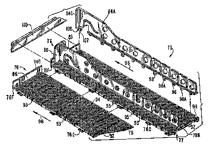
Figure 15 shows a top rear prospective view of display track 75 comprising
display
track unit 76 which is attachable to an adjacent display track unit 77 by
connections
76C, as described earlier.
Each display track unit as seen in Figs. 15 and 15A is formed by a plurality
of
longitudinally extending product support means or ribs 92 which are bounded on
each
marginal side by a longitudinally extending left side marginal support 93 and
right side
marginal support 94. There are a plurality of transversely extending beams 95
which
extend between marginal side walls 93 and 94 and engage each of the
longitudinally
extending ribs 92. This entire display track is preferably formed by a single
operation
injection molding procedure. The aligned ribs 92 [define an upper surface
which is the]
have top surfaces lying in a top plane at a first level defining a track or
product support
surface where products are situated and slide downward to the left in the
direction of
arrow 96, which is to the front of this product.
Since the side walls 93 and 94 extend downward below the bottom surface 92C of
longitudinal ribs 92, as seen in Figs. 1,5, 15A, 16 - 18, 22 - 24 and 26,
there is established
a basement 92B wherein said bottom surfaces of ribs 92C form the
280830.1
CA 02732193 2011-02-18
=
ceiling of the basement. This basement is a chamber bounded by said ceiling
92C, side
walls 93, 94 and front and rear end walls 76F, 76R. As seen, these track units
are
essentially flat on top devoid of upstanding side walls, and define a basement
chamber
beneath the longitudinal ribs 92 that provides a space for secure but
releasable coupling
of the partitions 82 - 85 to the track units and for secure but releasable
coupling one
track unit to another. Since one objective is to maximally utilize the total
vertical height
in the cabinet, the basement allows an unobstructed top surface of each track
unit and a
space of shallow depth beneath each top surface for all the coupling
requirements. As
will be further described below, the transverse beams 95 being spaced apart in
the front-
to-rear direction, provide sub-chambers, to accommodate and support engagement
of
the coupling elements of the partitions and engagement of the further coupling
elements
for joining display track units as lateral extensions in the transverse
direction, and/or as
longitudinal extensions in the front-to-rear direction.
The longitudinal ribs 92 are seen more clearly in Figures 22 - 27 where their
cross-section is shown as a generally triangular shape with a slightly rounded
top edge
97, the top edge being of relatively small area to minimize friction between
it and the
products which are supported and slide thereon. The triangular cross-section
also
provides adequate strength against bending of the beam, and the inclined sides
provide
a taper which enables removal of the product from the injection mold after
injection is
completed.
The partitions can be installed essentially anywhere in the transverse
direction
between any two adjacent longitudinal ribs of any track unit, and even
280830.1
CA 02732193 2011-02-18
-25-
between two adjacent marginal side walls of two adjacent but coupled-together
track units. Two different embodiments of partitions are illustrated herein.
Both
have the same general shape and construction of the upstanding body part or
blade
part, but each has a different lower part that functions as the coupling
element for
engagement to a display track unit.
The upstanding partitions have various forms and combinations. Frig. 14
shows a set of partitions 84, 85 and 84A, where partitions 84 and 84A each
have
a short right angle wall 84C which serves as a stabilizer and/or stop for
articles
sliding downward against said stop. Between partition 84 and 84A is the
intermediate partition 85 whose front end terminates in the cathedral stop 88
which cooperates with the adjacent right angle stops 84C.
To the right of partition 84 is the plain partition 83 which has no elevated
body part like the one seen at the front of partition 85 and no front stop
part,
except for the standard stop 86 formed as a transverse lip. On the lower shelf
73
the partitions on the display tracks have the transverse lip 86 (not seen)
plus a lip
extender 160 to extend the height of lip 86, as seen more clearly in Figs. 15
and
17 and further described below.
A first embodiment of the partitions is illustrated by Figs. 15, 19 and 22 -
24; a second embodiment is illustrated in Figs. 17, 25 and 26. As seen in Fig.
15,
partition 84A has coupling element 98 extending downward from its bottom edge.
When this partition is installed on a display track unit, as seen in Figs. 22-
24, the
partition is positioned to be aligned with a pair of adjacent spaced apart
longitudinally ribs 92 and to have its coupling elements 98, seen in Figs. 15,
19
CA 02732193 2011-02-18
- ¨
and 22 - 24, positioned between a pair of adjacent ribs 92. The partition is
forced
downward causing each element to be inserted between ribs which causes one or
more
ribs to deflect and/or causes the coupling element to deflect, such that the
element
descends until its releasable locking tooth 99 descends to a position below
the bottom
edge 92C' of longitudinally extending rib 92, where it locks thereunder. This
tooth
remains locked until the partition is forcibly pulled upward.
As further illustrated in Figs. 22 - 24, inclined surface 104 of the tooth 99A
allows
the lower portion 105 of this coupling element to cam outward and flex as the
partition
is pulled upward and the element is released from said locked position between
two
longitudinal ribs. The space L between longitudinal beams 92 is defined by a
pair of
tapered walls 92A and 92B which together form a triangular shape tapering from
a
wider opening at the top to a smaller opening at the bottom. Surfaces 92A, 92
are
dimensioned to receive and hold surfaces 92C, 92D respectfully of the lower
portion or
coupling element 98 of the partition 82.
In Fig. 22 locking tooth 99A of the coupling element 98 initially rides
against
surface 92A, then is deflected inward as indicated by arrow loo, until tooth
99A
descends and locks just below rib 92 as seen in Fig. 23.
As further seen in Fig. 23 surfaces 92C, 92D of the downward coupling element
98 of the partition lie against and are snugly supported by surfaces 92A, 92B
of opposite
faces of ribs 92A and 92B. Fig. 24 shows a coupling connection the same as
that of Figs.
23, but longitudinally displaced therefrom as seen in Figs. 15 and 19. Thus,
teeth 99A,
99B on elements 98, 98A are alternately directed left and right along the
length of the
partition. This helps to stabilize the partition in
280830.1
CA 02732193 2011-02-18
-27-
both: transverse directions, and also facilitates insertion of the partition
by a
downward force and removal by an upward force with slight tilting or rocking
to
= cause dislodgement of the locking teeth 99A, 99B.
Each of these first embodiment partitions has additional means to insure
that after it is inserted, it does not easily dislodge due to movement of
product or
due to touching by users or retail customers. As seen in Fig. 19 the partition
has
a tab 107 which has a forward extending finger part 108. The partition is
installed
downward and then slid forward, and the finger 108 moves under a rearward
extending bar 109, as seen in Flg. 17, extending rearward from the front
wal1110
of the display track unit. Finger 108 becomes releasably locked under bar 109.
The second embodiment 119 of the partition as seen in Figs. 25 and 26
utilizes releasable locking tabs 120A-120D with forward directed fingers 121A-
121D respectively. Tab 120A and its finger 121A are similar to tab 107 and
fmger
108 in Figs. 17 and 18; however, this partition 119 has no transversely
directed
locking finger 99 seen in Figs. 22-24. As seen in Fig. 26, partition 119 has a
plurality of longitudinally spaced, forwardly directed fingers 121A-121D
which,
acting together, restrain the partition from being dislodged or lifted at any
point
along its length, until it is specifically pushed rearwardly to disengage all
the
fingers 121A-121D from beneath the respective transverse bars 122A-122D of
display track unit 123. Fig. 26 does not show the forwardmost finger 121A and
bar
121D which corresponds in shape and function to those seen in Fig. 17. In one
variation of this embodiment there would be only two forwardly directed
fingers,
namely one at the front end of the partition and a second situated either at
the rear
CA 02732193 2011-02-18
-28-
of the partition or at the rear of the primary segment of the partition before
the
first break-away area. Accordingly, no matter how many segments were broken
away, at least the always-remaining primary and forwardmost segment would be
downwardly restrained unless and until it were slid rearward.
Fig. 26A illustrates a variation of the partition and display track
connection.
In Fig. 26A partition 119 'has downwardly directed fingers 1201?-120D', each
having a forwardly directed finger 121B'-121D' which engage respectively
transverse beams 124B-124D which extend across the display track between the
outer side walls and beneath the longitudinal ribs. Each of beams 1243 - 124D
is
situated between two adjacent principal transverse beams, such as those marked
122B'-122D'. A typical finger 121C' engages under a beam 124C when the
partition 119' is slid forwardly, and this coupling releasably secures the
partition
to the display track.
Since there is the possibility of the partition being accidentally pushed
. rearward by a store operator or by a customer, a third embodiment 130 of the
partition as seen in Fig. 28. This partition has a spring element 131 whose
finger
132 resiliently pushes in a rearward direction of arrow 133 against transverse
bar
134 of the display track unit. This resiliently urges the partition 130 in the
forward
direction of arrow 135 and thus urges locking finger 108 to remain beneath
transverse bar 109. This prevents any accidental rearward movement of the
partition and accordingly prevents accidental or unintentional upward movement
of the partition out of its proper position and alignment.
CA 02732193 2011-02-18
cP9 ¨
In this embodiment spring element 131 is formed as a trigger 137 having a
relaxed
state as shown, and which is movable upward to the position indicated by
dotted line
138 so that finger 132 clears transverse beam 134, and the partition can be
slid rearward.
This trigger is formed by cut-out portions 139, leaving finger hole 140 for
easy
engagement by the user.
A further embodiment of a partition with a trigger release is illustrated in
Fig. 29
where for convenience elements corresponding to those in Fig. 28 are given the
same
reference number followed by an "A". Accordingly, in Fig. 29 of the partition
130A has a
finger 132A extending from a resilient trigger element 137A, the latter be
defined by
cutout area 139A. This partition has a front locking finger 135A that
functions is finger
135 in Fig. 28.
In Fig. 29 partition 130A has, in addition to forward finger io8A, a rear
finger
io8B which extends forwardly beneath transverse rib 134D on transverse beam
134C.
Fig. 15 illustrates the separable segments of partition 84A to reduce its
length as desired,
and it is useful to have a separate finger io8B of Fig. 29 extending from the
bottom of
each of said separable segments so that all remaining segments after severing
will have
floor-engaging means. This will assure restraint from lifting either end of
the partition
unless and until it is slid rearwardly to first disengage its floor-engaging
means.
As discussed above, each display track unit has breakaway areas so that
longitudinally extending segments of track can be removed. Also, as discussed,
such
longitudinally extending segments can be added by using the transverse
releasable
connectors marked 76C in Fig. 15-18. A typical connector as seen in
280830.1
CA 02732193 2011-02-18
-30-
Fig. 18, has a transverse base 140, an upward stem 141 and a transverse
locking
finger 142. At a corresponding longitudinal location the adjacent display
track
segment to be attached has a window 143 and a latching lip 144. The engagement
=
of locking finger 142 and latching lip 144 occurs in the basement portion 92B
of
the track unit as seen in Figs. 17 and 18. This basement structure described
above
provides rapid, easy and secure releasable coupling while utilizing the height
aspect of the space efficiently.
The coupling elements for longitudinal extension of track as described
above also utilize this basement structure to create and interlock both the
male and
female components thereof.
A still further feature is a front lip extender 160 illustrated in Figs. 15,
16,
17 and 28. As seen in Fig. 15 a display track unit 77 may be extended
transversely
by the coupling thereto of adjacent display track unit 76. For this connection
coupling members 76C of track unit 77 engage in mating coupling elements
formed in the basement structure of display track unit 76, the detail of which
is
seen in Fig. 18: Because this coupling is designed to be easily engageable and
disengagable, it is less rigid than an integral construction against downward
bending of one display track with respect to the other. Normally bending is
not a
problem since these display track units are supported on a horizontal shelf;
however, to enhance the strength of this assembly against bending there is
provided the front lip extender 160 which releasably attaches to the front lip
portions of coupled display track units. Fig. 15 shows the display track units
to
have a front stop wall or lip 86, and lip extender 160 is applied to these
lips. Fig.
CA 02732193 2011-02-18
=
--
17 shows the front stop wall designated no with a top lip noT displaced
slightly
outward leaving a small slot 1108 behind lip 110T.
The lip extender 160 is a strip having a bottom lip 1643B which engages under
bottom edge 76F of the display track front wall, and has top flange 3.60T
which locks
over and behind lip noT and into slot 110S. Lip noT is also seen in Figs. 15
and 27.
When lip extender 160 is engaged to two or more aligned and coupled display
track
units, the strength of the assembly against bending is greatly enhanced,
particularly
because the lip extender has a high height to thickness ratio and thus is
subject to shear
forces rather than bending. This lip extender is quickly and easily attachable
and
removable, and serves the added function of heightening the stop wall to
prevent
products from falling forward.
Fig. 27 discloses a further structural feature which may be used as a "candy
blocker" with any of the display tracks and partitions described above. This
structure is
particularly useful with gondolas where the shelf is formed as a wire rack
3.50 having a
transverse front wire 151. The display track unit 152 has upward extending
recesses or
notches 153 and 154. The new display track is positioned downward until its
recess 153
overlies a transverse wire 151 of the rack. This engagement positions the
display track
properly and prevents it from moving forward or rearward. The plurality of
notches 153,
154 allows the display track to be moved as far forward as possible toward the
front door
155 of the cabinet 156 to the position shown by dotted lines 158A, 1588. In
this forward
position the display track is sufficiently close to door 155, that a store
operator
280830.1
CA 02732193 2011-02-18
is prevented from installing on the inside of door 155 a container 157 for
candy bars or
the like.
280830.1
CA 02732193 2013-01-03
-32-
Such a container, if it were installed, would extend rearward from the front
door,
and would block the retail customers' view of what products were on the
display
track. Obviously, it is in the interest of those selling products in the
display tracks,
that such products be seen without obstruction or distraction.
Fig. 30 illustrates the concept that a display track 1.65 on the downward
inclined gondola shelf 166 can be restrained from sliding forward in the
direction
of arrow 165 by restraining means which may take the form of pins 168 as
shown,
or tie wires 169 coupling the display rack to the rear of the shelf, or by
other well
known means.
Figs. 31. and 32 illustrate one final embodiment where a channel 21.0 with
upstanding flanges 230 is secured below display track 72. The channel is
strong
metal such a steel or aluminum and extends longitudinally. Releasable coupling
is achieved by spring fingers 200 which extend from the display track
downwardly
into slots 220 of the channel. The track 72 includes grooves 240 th receive
the
flanges 230. The channels reside within the display track basement and provide
substantial added strength and stability against bending and/or twisting of
the
display track when loaded.
The scope of the claims should not be limited by the preferred
embodiments set forth in the examples but should be given the
broadest interpretation consistent with the Decription as a whole.