Note: Descriptions are shown in the official language in which they were submitted.
CA 02732257 2011-01-27
WO 2010/042283 PCT/US2009/055539
EQUALIZED HYDRAULIC CLAMP FORCE CONTROL
BACKGROUND OF THE INVENTION
[0001] This disclosure relates generally to hydraulic valve circuits for use
with material
handling equipment and, more particularly, to hydraulic valve circuits adapted
for weight-
responsive control of clamping members associated with material handling
equipment having
free lift masts.
[00021 Standard forklifts and other types of material handling equipment
typically have mast
assemblies for hoisting or lifting a load from one height to another, and such
mast assemblies
are typically configured to receive a variety of attachments that may be
designed for handling
particular types of loads. For example, load-clamping attachments such as
carton clamps or
paper roll clamps may be used, each having hydraulically controllable load-
clamping members
for imparting sufficient gripping forces on the sides of a load to allow
lifting and carrying the
load from one place to another.
[0003] Mast assemblies are typically one of two general types -- "free lift"
or "non-free lift."
Free lift masts permit lifting a load from one height to another throughout a
"free lift" range of
motion without a corresponding change in the overall height of the mast
assembly. Lifting the
load beyond the free lift range of motion requires the mast to telescope so as
to extend the
range of lifting. The mast may have several stages which telescope in
succession, one after the
other. Each stage will generally have one or more extensible hydraulic
cylinders which, when
activated, extend fully before activation of the one or more extensible
hydraulic cylinders
associated with the next stage. The hydraulic cylinders in each successive
stage usually require
higher hoist pressures for activation than cylinders of the preceding stage.
Consequently, in a
free lift mast having, for example, a free lift range of lifting motion and a
main lift range of
lifting motion, the main lift cylinder or cylinders will not begin to extend
until the free lift
cylinder or cylinders have reached their fully extended position.
[0004] By contrast, non-free lift masts begin to telescope immediately as the
load is lifted.
Such telescoping of the mast is undesirable in overhead constrained
environments. For
example, the interior of enclosed tractor trailers may be limited to, for
example, an inside height
of 104 inches. If the particular lift truck has a collapsed mast height of
between 79 to 84
inches, as is common for counterbalanced sit-down lift trucks, there may be
only 20 to 25
-~-
CA 02732257 2011-01-27
WO 2010/042283 PCT/US2009/055539
inches of vertical space available for the mast to telescope before further
telescoping of the
mast interferes with the ceiling of the trailer.
[0005] In part because free lift masts typically require stepped or
progressively higher hoist
line pressures for extending the mast beyond the free lift range of motion,
principally hydraulic
control systems adapted to utilize hoist line pressures for sensing load
weight and
correspondingly regulating gripping forces automatically in response to such
pressures have not
been achieved with such masts. Alternative designs using electronic
controllers for such
gripping force regulation have disadvantages such as higher unit costs and
added system
complexity, as well as the requirement for electrical conductors which must be
movable in
response to mast extension. Therefore, different hydraulic valve circuits are
needed for
automatic weight-responsive force control of load-clamping members associated
with material
handling systems having free lift masts.
BRIEF DESCRIPTION OF THE DRAWINGS
[0006] For a more complete understanding of the present invention, the
drawings herein
illustrate exemplary hydraulic circuitry in accordance with various
embodiments of the
invention. The drawings, however, do not limit the scope of the invention.
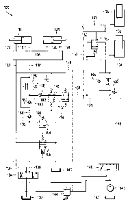
[0007] FIG. 1 is a schematic of a load-lifting system having a free lift mast
and various
hydraulic valve circuitry adapted for weight-responsive control of load-
clamping members, in
accordance with various embodiments.
[0008] FIG. 2 is the schematic in FIG. 1 with a solenoid-controlled two-way
hydraulic valve
as an exemplary alternative to the plunger-activated valve in FIG. 1.
DETAILED DESCRIPTION OF PREFERRED EMBODIMENTS
[0009] In the following detailed description, numerous specific details are
set forth in order
to provide a thorough understanding of various embodiments. However, those
skilled in the art
will understand that the present invention may be practiced without these
specific details, that
the present invention is not limited to the described embodiments, and that
the present
-2-
CA 02732257 2011-01-27
WO 2010/042283 PCT/US2009/055539
invention may be practiced in a variety of alternate embodiments. In other
instances, well
known methods, procedures, components, and systems have not been described in
detail.
[0010] An exemplary circuit diagram of a load-lifting system 100 having a free
lift mast and
various hydraulic valve circuitry adapted for weight-responsive control of
load-clamping
members in such a system is provided in FIG. 1. The system 100, as shown,
generally
includes one or more fluid power actuators 101, 103 capable of operating in
unison to apply a
gripping force to a load held between load-clamping members (not shown). At
least one
elongate, longitudinally-extensible fluid power lifting device shown
schematically in FIG. 1 has
a free lift stage 154 and a main lift stage 156. Manually operated load-
clamping 134 and
load-lifting 146 selector valves, and various hydraulic valve circuitry for
controlling the
operation of the fluid power actuators 101, 103 and lifting device 154, 156 in
response to
manual operation of the selector valves 134, 146, are provided.
[0011] The load-clamping members, at least one of which is controllable by one
or more of
the fluid power actuators 101, 103, may comprise paper roll clamp arms or any
type of load-
clamping members controllable by at least one fluid power actuator. For
example, the load-
clamping members may comprise clamping arms in a carton clamp attachment. For
purposes
of this disclosure, however, the load-lifting system 100 will be described in
the context of a
paper roll clamp attachment having a pair of load-clamping members arranged
for operation in
tandem, each load-clamping member controlled by one of the fluid power
actuators 101, 103.
In a tandem arrangement, the fluid power actuators 101, 103 may be configured
for closing
the load-clamping members as hydraulic fluid is introduced into the head sides
of the fluid
power actuators (or cylinders) 101, 103 via fluid lines (or hydraulic fluid
conduits) 118, 120
and as hydraulic fluid is concurrently exhausted from the rod sides of the
fluid power actuators
101, 103 via fluid lines 122, 124.
[0012 Each of the power actuators 101, 103 may be controlled by a load-
clamping valve
assembly 126, which comprises hydraulic circuitry for closing or opening the
load-clamping
members. The specific circuitry used for the load-clamping valve 126 may
comprise
conventional circuitry for operating at least one of the power actuators 101,
103 for selectively
closing or opening load-clamping member in response to at least one load-clamp-
closing line (or
hydraulic fluid conduit) 130 and at least one load-clamp-opening line 132. The
load-clamping
valve assembly 126 may, for example, include pilot-operated check valves and
associated
-3-
CA 02732257 2011-01-27
WO 2010/042283 PCT/US2009/055539
circuitry for controlling the clamping members of a paper roll clamp
attachment. As another
example, the load-clamping valve assembly 126 may include pilot-operated check
valves and a
fluid divider/combiner for controlling the clamping members of a carton clamp
attachment.
[0013] As shown schematically in FIG. 1, the lifting system 100 includes at
least one
elongate, longitudinally-extensible fluid power lifting device 154, 156, which
has a free lift
stage 154 and at least one main lift stage 156. The lifting device 154, 156
may be a single,
multiple stage fluid power device having a free lift range of motion (shown
schematically in
FIG. 1 as 154) and at least one main lift range of motion (shown schematically
in FIG. 1 as
156). The lifting device 154, 156 may, however, comprise an assembly of fluid
power devices
configured to have a free lift range of longitudinal movement for lifting the
load-clamping
members without unfolding of the mast and at least one main lift range of
longitudinal
movement whereby the mast unfolds as the lifting device extends. As shown
schematically, the
free lift stage 154 requires a lower fluid pressure in line 158 for extensible
actuation than the
main lift stage 156 because the free lift stage 154 piston has a larger
pressure surface area
than the main lift stage 156 piston. Consequently, increasing hydraulic fluid
to line 158 causes
extension of the free lift stage 154 until its end of travel, after which
increasing fluid to line
158 causes the main lift stage 156 to begin to extend.
[0014] The hydraulic valve circuitry in FIG. 1 is shown grouped into three
different modules
or valve assemblies 128, 150, and 152, although various components may be
grouped
differently or grouped into a different number of modules or valve assemblies.
The circuitry in
150 and 152 may, for example, comprise a single module or valve assembly.
Further, portions
of the circuitry in FIG. 1 may be used independently or with substituted
circuitry. For example,
the circuitry in 150 and 152 may be used with circuitry different than that
shown in 128.
[0015] The hydraulic valve circuitry grouped into the valve assembly 128, as
shown,
comprises circuitry for receiving a sensed load weight in line 168 from
hydraulic circuitry
associated with the lifting device 154, 156, and for using the sensed load
weight for weight-
responsive control of the load-clamping members. The hydraulic valve circuitry
grouped into
the valve assemblies 150 and 152 include circuitry for ensuring that the
sensed load weight
received in line 168 is equalized so as to be substantially independent of the
longitudinally-
extensible position of the lifting device 154, 156, and for enabling the
cylinder or cylinders that
comprise the lifting device 154, 156 to act as accumulators when the load-
clamping 134 and
-4-
CA 02732257 2011-01-27
WO 2010/042283 PCT/US2009/055539
load-lifting 146 selector valves are closed, thereby providing the load-
lifting system 100 with
full-time automatic weight-responsive force control of the load-clamping
members.
[00161 The hydraulic valve circuitry shown in the valve assembly 128 includes
load-clamp-
closing circuitry for receiving hydraulic fluid from a load-clamping selector
valve 134. For
example, an operator of a lift truck equipped with a load-lifting system 100
for handling paper
rolls may initiate closure of the load-clamping members by moving a load-
clamping selector
valve 134 to cause hydraulic fluid to flow from pump 142 into load-clamp-
closing line 136,
unseat the pilot-operated valve 190, and continue flowing to the load-clamping
valve 126 via
first fluid conduit 186 and then fluid conduit 130. As the fluid is introduced
into the load-
clamp-closing line 130, hydraulic fluid is concurrently exhausted through the
load-clamp-
opening line 132. The spring biased, normally open two-way valve 196 provides
a path for
fluid exhausted through the load-clamp-opening line 132 to return to the
reservoir (or tank)
140. The two-way valve 196 is shown piloted from the load-clamp-opening line
138 causing
the valve to move to a closed, no flow position when the load-clamping
selector valve 134 is
positioned for increasing fluid pressure in the load-clamp-opening line 138.
Safety relief valve
144 is provided to return fluid back to the reservoir 140 if excessive
pressure develops in the
system 100.
[0017] As the load-clamping members close upon the load, imposing a gripping
force upon
the sides of the load, hydraulic pressure in the load-clamp-closing line 136
increases to a
desired threshold (or starting) gripping pressure by an adjustable pressure
relief valve 194 or
other suitable valve. For example, the pressure relief valve 194 may be set to
limit the load-
clamp-closing line 136 to 650 psi so that hydraulic fluid from the load-
clamping selector valve
134 exceeding this limit is returned to the lift truck reservoir 140 rather
than allowed to
continue to increase the gripping pressure imposed on the clamped load.
[0018] As the fluid pressure increases in the load-clamp-closing line 136 up
to the setting of
the pressure relief valve 194, i.e. the threshold pressure, the fluid pressure
sensed immediately
downstream of the pilot-operated check valve 190, at 184, also increases up to
the threshold
pressure. The pilot line 174 receives the sensed pressure at 184 for
controlling the position of
two pilot-operated, adjustably spring biased two-position valves 172, 176,
which are used to
selectively control the range of fluid pressure accepted from line 168 and
hydraulic circuitry
associated with the lifting device 154, 156. The valve 172 is preferably used
to set a lower
-5-
CA 02732257 2011-01-27
WO 2010/042283 PCT/US2009/055539
pressure limit below which the load-clamp-closing circuitry is hydraulically
decoupled from the
load-lifting circuitry, and the valve 176 is preferably used to set a maximum
clamping pressure
above which the load-clamp-closing circuitry is hydraulically decoupled from
the load-lifting
circuitry. The two-position valve 176 is shown as a normally open valve,
allowing fluid flow
unless piloted by line 174 into a closed or no fluid flow state, whereas the
two-position valve
172 is shown as a normally closed valve, blocking fluid flow unless piloted by
line 174 into an
open, fluid flow state. Each of the two-position valves 172, 176 is spring
biased so as to
remain in its normal state until the pilot line pressure exceeds the setting
of the spring
resistance. Pressure in the load-clamp-opening line 132 and spring override
line 170 causes
the valves 172, 176 to return to their normal state. Pressure in the load-
clamp-opening line
132, 138 also unseats the check valve 190 via pilot line 192 allowing fluid to
drain from the
load-clamp-closing circuitry.
[0019] Preferably the spring resistance setting for valve 172 is less than the
threshold or
starting pressure setting for the pressure relief valve 194 yet high enough to
prevent the load-
clamping members from drifting downward as they are being closed for gripping
the load.
Typical spring resistance settings may be 600 psi for the spring in valve 172
and 1800 psi for
the spring in valve 176. Once the fluid pressure sensed at 184 reaches the
spring setting of
valve 172, or 600 psi, for example, valve 172 opens to allow fluid pressure to
be sensed
downstream of now open valve 172, downstream of the normally open valve 176,
and also
downstream of check valve 178. When both valves 172 and 176 are open, fluid
pressure
from line 168, and thereby the weight of the load, may be sensed at 180. Until
valve 172
opens, the pressure in the load-clamp-closing circuitry is decoupled from
pressure in the hoist
lines 148 and 168. Only when both of the two-position valves 176 and 172 are
open is fluid
from line 168 able to be received into the load-clamp-closing circuitry at
180. The check valve
178 prevents fluid from the load-clamp-closing circuitry from flowing through
line 168 back
into the load-lifting circuitry.
[00201 The check valve 182 prevents fluid from the line 168 from flowing
upstream in the
load-clamp-closing circuitry, instead forcing fluid to flow through the
pressure regulating valve
188. The pressure regulating valve 188 may be used to adjust the clamping
pressure applied
by the load-clamping members in relation to weight-proportional fluid pressure
received
through the line 168. For example, for a lifting system having larger capacity
fluid power
-6-
CA 02732257 2011-01-27
WO 2010/042283 PCT/US2009/055539
actuators 101, 103, the weight-proportional hydraulic pressure received from
the line 168 may
result in excessive gripping forces exerted on the load. In such cases the
pressure regulating
valve 188 may be used to reduce the maximum pressure available for gripping
the load. Other
factors such as the fragility and stability of certain types of loads, the
size and capacity of the
load-lifting cylinder or cylinders comprising the lifting device 154, 156,
and, as will be
described in greater detail below, the pressure intensification effects of
pressure equalizing
circuitry 150 associated with the lifting device 154, 156 may require reducing
the clamping
pressure received from line 168.
[0021] Any suitable type of pressure regulating valve variably responsive to
the pressure in
line 168 can be used in the position of valve 188, including one or more pilot-
controlled relief
valves or pressure reducing valves.
[0022] During a load-lifting operation, after the threshold pressure is
reached for clamping
the load the load-clamping selector valve 134 is returned to its centered,
unactuated position,
and the hoist or load-lifting selector valve 146 is moved to allow hydraulic
fluid to flow from
pump 142 into hoist actuating line 148 for extending the lifting device 154,
156 to lift the
load. If the fluid conduits 148, 158, and 168 are simply interconnected
together, the
relationship between load weight sensed at line 168 and the hydraulic pressure
in the line 168
would vary depending upon the position of the lifting device 154, 156 because
lifting the load
in free lift 154 requires less hydraulic pressure than lifting the same load
in main lift 156. The
main lift stage 156 may, for example, require an additional 400 psi of
hydraulic pressure for
activation. Consequently, the load weight signal available from such a lifting
system varies
depending upon whether the lifting device is in free lift or main lift.
[0023] The hydraulic valve circuitry grouped into the valve assemblies 150 and
152 includes
circuitry for ensuring that the sensed load weight received in line 168 is
equalized so as to be
substantially independent of the longitudinally-extensible position of the
lifting device 154,
156. As shown, the exemplary valve assembly 150 includes a pressure-
differential regulating
valve 164 that compensates for the difference in actuation pressures between
free lift cylinder
154 and main lift cylinder 156. The pressure regulating valve 164 may be
adjusted, for
example, to reduce the pressure in line 158 by 400 psi to operate the free
lift cylinder 154, as
compared with the higher downstream pressure required in line 158 to operate
the smaller-
area piston of the main lift cylinder 156. During operation of the free lift
cylinder 154 the
-7-
CA 02732257 2011-01-27
WO 2010/042283 PCT/US2009/055539
pressure in line 148 is effectively intensified by the valve 164 so as to
equalize the sensed load
weight in line 168 to that which naturally occurs during operation of the main
lift cylinder 156.
[0024] During free lift 154, as the load is lifted without telescoping of the
mast, the main lift
stage 156 remains stationary. In one embodiment, a valve assembly 152,
comprising a
normally closed, plunger-activated two-way valve 160, is mounted to a cross
member of the
lowest (fixed) mast section below a cross member 198 of the movable main lift
telescoping
section of the mast. After the free lift stage 154 reaches its upper end of
travel, the main lift
cross member 198 moves upwardly from the plunger 162 as the main lift stage
156 is
actuated, thereby allowing the pressure in line 168 to move the two-way valve
160 to its open
position. This enables fluid to bypass the equalizing valve 164, eliminating
its pressure-
reducing effect. As additional hydraulic fluid is introduced through line 148
to continue lifting
the load, the fluid is able to bypass the equalizing valve 164 so that the
higher pressure in line
148 is available for actuating the main lift stage 156 of the lifting device
154, 156. Other
types of valves or components may be used for bypassing the equalizing valve
164 when the
lifting device 154, 156 is in its main lift 156 range of motion.
[0025] When retracting the lifting device 154, 156 in its main lift 156 range
of movement,
hydraulic fluid is permitted to flow through the two-way (or bypassing) valve
160. Once the
two-way valve 160 becomes closed (when the main lift cross member 198
depresses the
plunger 162) fluid is able to bypass the equalizing valve 164 by flowing
through the check
valve 166, which in turn provides a path for hydraulic fluid to exhaust from
the free lift stage
154 as the lifting device 154, 156 is further retracted.
[0026] The check valve 166 also enables the cylinder or cylinders that
comprise the lifting
device 154, 156 to act as accumulators when the load-clamping 134 and load-
lifting 146
selector valves are closed, thereby providing the load-lifting system 100 with
full-time
automatic weight-responsive force control of the load-clamping members. If,
for example,
there is an increase in the magnitude of sensed load weight, the check valve
166 enables fluid
from the lifting device 154, 156 to automatically increase fluid to the load-
clamp-closing
circuitry through line 168 without concurrent actuation of either the load-
clamping 134 or
load-lifting 146 selector valves. Similarly, if there is a decrease in the
gripping force exerted on
the load, the check valve 166 enables fluid from the lifting device 154, 156
to automatically
-8-
CA 02732257 2011-01-27
WO 2010/042283 PCT/US2009/055539
increase fluid to the load-clamp-closing circuitry without concurrent
actuation of either the load-
clamping 134 or load-lifting 146 selector valves.
[00271 Although a valve assembly 152 comprising a plunger-activated two-way
valve 160
has been described, the valve assembly 152 may comprise, for example, a switch
204 that is
responsive to the extensible position of the mast and that provides an
activation signal via
electric wires 206 to a normally open, solenoid-activated two-way valve 200 in
valve assembly
150, as shown in FIG. 2. The solenoid-activated two-way valve 200 is shown in
FIG. 2 in an
activated, closed position to be consistent with FIG. 1, which shows the two-
way valve 160 in
a closed (blocked) position for operation of the lifting device 154, 156 in
its free lift 154 range
of movement. In one embodiment, a switch triggering element or other device
such as, for
example, a target 202 may be mounted to a cross member 198 of the movable main
lift
section of the mast and a switch 204 (such as a proximity switch) may be
mounted on the
lower or fixed portion of the mast. In one embodiment, a proximity switch 204
provides an
activation signal causing the solenoid-activated two-way valve 200 to remain
in an activated,
closed position throughout extension of the lifting device 154, 156 in its
free lift 154 range of
movement. After the free lift stage 154 reaches its upper end of travel, the
main lift cross
member 198 moves upwardly away from the fixed portion of the mast, thereby
separating the
switch elements and causing de-activation of the solenoid-activated two-way
valve 200, which
in turn moves the two-way valve 200 to its open position. This enables fluid
to bypass the
equalizing valve 164, eliminating its pressure-reducing effect. As additional
hydraulic fluid is
introduced through line 148 to continue lifting the load, the fluid is able to
bypass the
equalizing valve 164 so that the higher pressure in line 148 is available for
actuating the main
lift stage 156 of the lifting device 154, 156. Even though the switch 204 and
solenoid valve
200 are electrical, they are both mounted on portions of the mast or lift
truck which are fixed
and do not move in response to mast extension, thereby avoiding the need for
any electrical
conductor which must move in response to mast extension and would therefore be
exposed to
hazards and durability problems. Other types of valves or components may be
used for
bypassing the equalizing valve 164 when the lifting device 154, 156 is in its
main lift 156
range of motion.
[0028] When retracting the lifting device 154, 156 in its main lift 156 range
of movement,
hydraulic fluid is permitted to flow through the two-way (or bypassing) valve
200. Once the
-9-
CA 02732257 2011-01-27
WO 2010/042283 PCT/US2009/055539
two-way valve 200 becomes closed fluid is able to bypass the equalizing valve
164 by flowing
through the check valve 166, which in turn provides a path for hydraulic fluid
to exhaust from
the free lift stage 154 as the lifting device 154, 156 is further retracted.
[00291 Although a two-stage (i.e. free lift and main lift) lifting device has
been described,
additional main lift stages may be accommodated by adding equalization and
bypassing valves
to compensate for the higher actuation pressures required so that the sensed
load weight at
line 168 remains independent of the longitudinally-extensible position of the
lifting device. For
example, if the lifting device includes a second main lift stage beyond the
single main lift stage
156 shown in FIG. 1, another equalization valve may be added in series with
equalizing valve
164, and another valve for bypassing the added equalizing valve may be added
for actuation of
the additional (second) main lift stage when the first main lift stage 156
reaches its end of
travel.
[00301 The terms and expressions which have been employed in the forgoing
specification
are used therein as terms of description and not of limitation, and there is
no intention in the
use of such terms and expressions of excluding equivalence of the features
shown and
described or portions thereof, it being recognized that the scope of the
invention is defined and
limited only by the claims which follow.
-10-