Note: Descriptions are shown in the official language in which they were submitted.
CA 02733515 2013-05-15
. .
Title: UMBILICAL FIELD CONNECT
Field of the Disclosure
[00011 The present disclosure relates generally to umbilicals employed in
subsea development projects, and more specifically, to a solution for
connecting
an umbilical to another device, such as a second umbilical or an umbilical
termination assembly.
Description of the Related Art
[00021 Subsea oil and gas fields often employ subsea well equipment that
io is
located on the seabed and tied back to a surface structure, such as a
production facility and/or ship. An umbilical is often used to convey fluids
and/or
send electrical and other communication signals between the surface structure
and the subsea well equipment. The umbilical can be many miles long with large
and heavy end terminations, making it difficult to handle and/or deploy.
[0003] Over time, the length and weight of umbilicals has continued to
increase. As a result of the increased size, the transportation and
installation of
the umbilicals is becoming more and more difficult. For example, in some cases
it may be difficult to locate an available sea-going vessel that has the
capacity to
ship and install a very large umbilical.
[0004] A known solution for handling a very long umbilical includes cutting
the umbilical and installing a subsea umbilical termination assembly ("SUTA")
on
one end and a Cobra Head on the other end. The connections between each
1
CA 02733515 2013-05-15
. .
end of the umbilical and the SUTA and Cobra Head are generally made in the
factory by, for example, welding. The two umbilical segments with the attached
SUTA and Cobra Head can then be separately transported to the deployment
site and connected. This approach has a number of disadvantages, including
that the on-site connection of the two segments of the umbilical with a SUTA
and
Cobra Head is performed below the surface of the ocean using an ROV.
Furthermore, the SUTA and Cobra Head equipment is costly and often requires
several months to manufacture.
[0005] FIG. 1 illustrates an example of a SUTA 10 connected to an
umbilical 20. SUTA 10 can be relatively large, often weighing several thousand
pounds. It is known to connect the umbilical 20 and SUTA 10 using a
connection assembly comprising a split barrel 30, an armor pot assembly 40,
and one or more bend restrictor clamps 50, all of which can be bolted
together.
Because of the size and weight of the SUTA, packing and handling during
transportation and deployment of the umbilicals can be difficult.
Additionally, the
connection between the umbilical and SUTA can potentially be a weak point
during transportation of the unit to the deployment site. Consequently, damage
can occur at the connection, which can result in the need for costly repairs.
[0006] The present disclosure is directed to overcoming, or at least
reducing the effects of, one or more of the issues set forth above.
2
CA 02733515 2013-05-15
SUMMARY OF THE DISCLOSURE
[00071 An embodiment of the present disclosure is directed to an umbilical
field connect assembly. The umbilical field connect assembly comprises: a
first
umbilical portion comprising two or more first bundled members chosen from
electrical cables, fluid conduits, and optical fibers; a second umbilical
portion
comprising two or more second bundled members chosen from electrical cables,
fluid conduits, and optical fibers; a first housing assembly having a first
end
coupled to the first umbilical portion and a second end comprising a first
coupling
plate having a plurality of first couplings chosen from male and female
couplings
lo positioned therein, one of the plurality of first couplings being
positioned at an
end of each of the first bundled members; a second housing assembly having a
third end coupled to the second umbilical portion and a fourth end comprising
a
second coupling plate having a plurality of second couplings chosen from male
and female couplings positioned therein, one of the second couplings being
Is positioned at an end of each of the second bundled members. The first
housing
and the second housing can be positioned so that each of the first couplings
join
with one of the second couplings to form mated coupling pairs, whereby the
first
bundled members of the first umbilical portion and the second bundled members
of the second umbilical portion can be joined in a manner that effectively
20 provides for a single functioning umbilical assembly.
100081 Another embodiment of the present disclosure is directed to a field
connect for an umbilical termination assembly. The field connect comprises an
3
CA 02733515 2013-05-15
umbilical comprising two or more bundled members chosen from electrical
cables, fluid conduits and optical fibers; an umbilical termination assembly
(UTA)
comprising two or more members chosen from electrical cables, fluid conduits;
and optical fibers; a first housing assembly having a first end coupled to the
umbilical and a second end comprising a first coupling plate having a
plurality of
first couplings positioned therein, one of the plurality of first couplings
being
positioned at an end of each of the first bundled members; a second housing
assembly having a third end coupled to the UTA and a fourth end comprising a
second coupling plate having a plurality of second couplings positioned
therein,
the second couplings being positioned at an end of each of the second bundled
members. The first housing and the second housing can be positioned so that
each of the first couplings join with one of the second couplings to form
mated
coupling pairs, whereby the first bundled members of the first umbilical
portion
and the members of the UTA are joined in a manner that effectively provides
for
a functioning connection between the umbilical and the UTA.
BRIEF DESCRIPTION OF THE DRAWINGS
[00091 FIG. 1 illustrates an example of a SUTA connected to an umbilical.
[00101 FIG. 2 illustrates an umbilical field connect assembly, according to
an embodiment of the present disclosure.
100111 FIG. 3 illustrates a portion of an umbilical having two or more
bundled members.
4
CA 02733515 2013-05-15
[0012] FIG. 4 illustrates first and second housing assemblies prior to
coupling, according to an embodiment of the present disclosure.
[0013] FIG. 5 illustrates a coupling plate having a plurality of female
couplings and guide pins holes positioned therein, according to an embodiment
of the present disclosure.
[0014] FIG. 6 illustrates a coupling plate having a plurality of male
couplings and guide pins positioned therein, according to an embodiment of the
present disclosure.
[0015] FIG. 7 illustrates an exploded view of a coupler assembly,
io according to an embodiment of the present application.
[0016] FIG. 8 illustrates an umbilical field connect assembly, according to
an embodiment of the present disclosure.
100171 FIG. 9 illustrates a split clamp casing assembly, according to an
embodiment of the present disclosure.
[0018] FIGS. 10 and 11 illustrate a field connect assembly for an umbilical
termination assembly, according to an embodiment of the present disclosure.
[0019] FIG. 12 illustrates a subsea well assembly, according to an
embodiment of the present disclosure.
[0020] While the disclosure is susceptible to various modifications and
alternative
forms, specific embodiments have been shown by way of example in the
drawings and will be described in detail herein. The scope of the claims
should
5
CA 02733515 2013-05-15
not be limited by the preferred embodiments and examples, but should be given
the broadest interpretation consistent with the description as a whole.
DETAILED DESCRIPTION
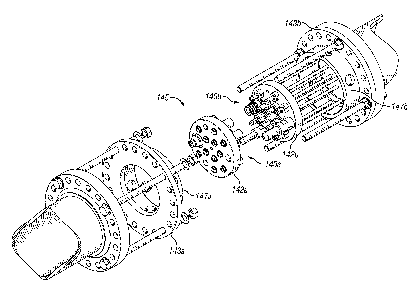
[0021] FIG. 2 illustrates an umbilical field connect assembly 100 according
to an embodiment of the present disclosure. Umbilical field connect assembly
100 includes a first umbilical portion 110a and a second umbilical portion
110b.
An umbilical portion 110 can include two or more bundled members 115,
similarly as illustrated in FIG. 3. Bundled members 115 can be chosen from
fluid
io
conduits, such as hydraulic lines and tubes for carrying fluids, such as oil
or gas;
and electrical cables and/or optical fibers for carrying electrical or optical
signals
for controlling or otherwise communicating with, for example, the subsea well
equipment. Umbilicals can extend between a surface structure or ship and
subsea well equipment, as is well known in the art.
[0022] Referring again to FIG. 2, umbilical field connect assembly 100
includes a first housing assembly 120a and a second housing assembly 120b,
which are shown coupled together. FIG. 4 illustrates the first and second
housing assemblies prior to coupling. The first housing assembly has a first
end
coupled to the first umbilical portion 110a. A bend restrictor assembly 130a
comprising one or more bend restrictor segments 132a and bend restrictor
clamps 134a can be employed. Bend restrictor assembly 130a is positioned
6
CA 02733515 2013-05-15
proximate the first housing assembly 120a to prevent overbending of the
umbilical adjacent to the field connect assembly 100.
[0023] As shown in FIG. 4, first housing assembly 120a has a second end
140a, the details of which are more clearly shown in FIGS. 5 and 7. Second end
140a includes a first coupling plate 142a (See FIG. 5) having a plurality of
female
couplings 144a and 146a and guide pin holes 148a that are positioned therein.
Generally one of the plurality of female couplings is positioned at an end of
each
of the first bundled members 115 (See FIG. 3) of the umbilical portion 110a.
[0024] Referring back to FIG. 2, second housing assembly 120b has a
io third end coupled to the second umbilical portion 110b. Similarly as
described
above for umbilical portion 110a, a bend restrictor assembly 130b comprising
one or more bend restrictor segments 132b and bend restrictor clamps 134b can
be employed proximate the second housing assembly 120b.
[0025] Second housing assembly 120b has a fourth end 140b, the details
of which are more clearly shown in FIGS. 6 and 7. The fourth end includes a
coupling plate 142b (See FIG. 6) having a plurality of male couplings 144b and
146b and guide pins 148b that are positioned therein. Generally one of the
plurality of male couplings is positioned at an end of each of the first
bundled
members 115 (See FIG. 3) of the umbilical portion 110b. Any suitable type of
female couplings and male couplings can be employed. Examples of such
couplings are well known in the art. The female couplings 144a and 146a and
the guide pin holes 148a of first housing assembly 120a can be respectively
7
CA 02733515 2013-05-15
aligned with the male couplings 144b and 146b and guide pins 148b of second
housing assembly 120b. The first and second housing assemblies 120a and
120b can then be positioned adjacent each other so that the male couplings are
received by the female couplings. In this manner, the bundled members 115 of
the first umbilical portion 110a and the bundled members 115 of the second
umbilical portion 110b can be joined in a manner that effectively provides for
a
single functioning umbilical assembly 190. The guide pin holes 148a and guide
pins 148b function to align coupler plates 142a and 142b and to prevent the
two
coupler plates from encroaching on a minimum gap allowance between the
io female couplings and the male couplings.
[00261 In the embodiment illustrated in FIGS. 4 to 6, the first housing
assembly 120a includes female couplings and the second housing assembly
120b includes male couplings. In other embodiments, the first housing assembly
120a can include a plurality of couplings, including one or more each of both
male and female couplings. Similarly, the second housing assembly 120b can
also include a plurality of couplings including one or more each of both male
and
female couplings, each of which corresponds to a mating coupling in the first
housing assembly 120a. Any arrangement of male and/or female couplings can
be employed that will effectively join the bundled members of the first and
second housing assemblies.
[0027] The first and second housing assemblies will now be described in
greater detail. As illustrated in FIG. 4, housing assemblies 120a and 120b can
8
CA 02733515 2013-05-15
include armor pots 150a and 150b, respectively. Armor pots are well known in
the art, and can include an outer casing 152 through which bundled members
115 extend, as illustrated in FIG. 8. The armor pot can include a casting
resin, or
potting resin, (not shown) inside the outer casing 152. The casting resin
forms a
resin matrix that can function to connect the armor pot to the umbilical,
holding
the bundled members of the umbilical in place so that they are not pulled out
from the umbilical when force is applied to the field connect assembly 100.
Armor pots 150a and 150b can also be connected to the bend restrictor
assemblies 130 via a flange assembly 156 (See FIG. 8). Any other suitable
to means for making the connection, such as welding, can also be employed
in
place of or in addition to the flange assembly 156.
100281 Referring again to FIG. 4, armor pots 150a and 150b are also
connected to split barrel assemblies 160a and 160b, respectively.
The
connection between the armor pots and the split barrel assemblies can be made
Is in any suitable manner, including using a flange assembly, a latching
mechanism
and/or by welding.
100291 The outer casings of split barrel assemblies 160a and 160b include
two halves 162 and 163. The outer casing half 162 and/or the outer casing half
163 can each be separately removed to allow easy access to the bundled
20 members 115 that are illustrated in FIG. 8.
[0030] Split barrel assembly 160a and/or split barrel assembly 160b can
include an electrical termination 165. Such electrical terminations are well
known
9
CA 02733515 2013-05-15
in the art for connecting electrical cables generally. In the present
disclosure,
electrical termination 165 allows for two or more electrical cables from the
umbilical portions 110a and 110b to be connected in the field connect assembly
100 using a single male electrical coupling 146b and female electrical
coupling
146a (See FIG. 6). Multiple electrical terminations 165 can be employed in a
split barrel assembly, depending upon the number of electrical cables to be
connected. Employing such electrical terminations can reduce the complexity
and size requirements of the field connect assembly 100.
[0031] Referring again to FIG. 4, the first split barrel assembly 160a and
the second split barrel assembly 160b are respectively connected to coupling
plate seating flanges 143a and 143b. The connections can be made in any
suitable manner, such as by bolting, welding or by other means. As is more
clearly illustrated in the exploded view of the coupler assembly 145 of FIG.
7,
coupling plates 142a and 142b are positioned in coupling plate seatings 147a
and 147b to form the mating ends 140a and 140b of the field connect assembly
100.
100321 First housing assembly 120a and second housing assembly 120b
can be fastened together in any suitable manner so that the female couplings
144a and 146a and guide pin holes 148a of the first coupling plate 142a and
the
male couplings 144b and 146b and guide pins 148b of the second coupling plate
142b are held together between the first coupling plate seating flange 143a
and
the second coupling plate seating flange 143b. In an embodiment, the first and
CA 02733515 2013-05-15
second housing assemblies can be fastened using a technique that allows for
easy decoupling of the housing assemblies. For example, the first split barrel
assembly can be bolted to the second split barrel assembly, or the first and
second split barrel assemblies can be fastened using a quick locking means. In
other embodiments, the first and second housing assemblies can be
permanently fastened together, such as by welding or any other suitable means.
[0033] In an embodiment, a split clamp casing assembly 170, illustrated in
FIG. 9, is fastened around the first and second housing assemblies 120a and
120b of FIG. 2. This can provide additional protection and support to the
field
io connect assembly 100. In an embodiment, split clamp casing assembly 170 is
bolted together to form a casing around the first split barrel assembly 160a,
the
coupler assembly 145 and the second split barrel assembly 160b. The split
clamp casing assembly 170 may provide a suitable lifting point for the field
connect assembly 100.
100341 FIGS. 10 and 11 illustrate a field connect assembly 200 for an
umbilical termination assembly, according to another embodiment of the present
disclosure. The field connect assembly 200 is similar to the field connect
assembly 100, described above, except that field connect 200 is designed for
connection to an umbilical termination assembly ("UTA") 210.
Umbilical
termination assembly 210 may be any device, other than an umbilical, into
which
an umbilical may be connected, including a subsea umbilical termination
assembly ("SUTA"). Such UTAs and SUTAs are well known in the art.
11
CA 02733515 2013-05-15
[0035] The field connect assembly 200 comprises housing assemblies
120a and 120b. Housing assembly 120b has a first end coupled to an umbilical
110 and includes an armor pot 150 and a split barrel assembly 160b, similarly
as
described above for housings 120a and 120b in the drawings of FIGS. 2 to 9. A
bend restrictor assembly 130 can also be employed similarly as described
above.
[0036] The housing 120a of FIG. 10 can have any suitable design or
structure that would provide for acceptable coupling to UTA 210 and housing
assembly 120b. In an embodiment, housing assembly 120a comprises a split
barrel assembly 160a coupled directly to UTA 210. The split barrel assembly
160a can be similar to the split barrel assemblies discussed herein above. The
UTA can include two or more members 115 chosen from electrical cables, fluid
conduits and optical fibers, which extend through split barrel assembly 160a,
similarly as shown in FIG. 8 above.
100371 A coupling assembly 145, similar to that shown in FIG. 7, can be
used to join the housing assemblies 120a and 120b of FIGS. 10 and 11. Female
couplings 144a, 146a and guide pin holes 148a and male couplings 144b, 146b
and guide pines 148b, as illustrated in FIGS. 5 and 6, can be interchangeably
used as part of either of housings 120a or 120b of FIGS. 10 and 11, so as to
provide a functioning coupling assembly 145. In an embodiment, a plurality of
couplings, including one or more each of both male and female couplings, can
12
CA 02733515 2013-05-15
be employed in the housings 120a, with corresponding mating couplings being
employed in housing 120b.
[0038] In an embodiment, a split clamp casing assembly 170, as
illustrated in FIG. 9, is fastened around the first and second housing
assemblies
120a and 120b of FIG. 10. This can provide additional protection and support
to
the field connect assembly 200. For example, split clamp casing assembly 170
can be bolted together to form a casing around the first split barrel assembly
160a, the coupler assembly 145 and the second split barrel assembly 160b.
[00391 FIG. 12 illustrates a subsea well assembly 250, according to an
io embodiment of the present application. The subsea well assembly 250 can
comprise, among other things, a subsea well device 225, such as, for example,
a
SUTA, positioned below the surface of the ocean. In an embodiment, an
umbilical 110 can be connected to the subsea well device using a field connect
assembly 200, as described herein above. In an embodiment, an umbilical 110
can be connected to the subsea well device 225, wherein the umbilical 110
comprises a plurality of umbilical portions 110a, 110b coupled together using
the
field connect assembly 100, as described herein above.
[0040] Although various embodiments have been shown and described,
the present disclosure is not so limited and will be understood to include all
such
modifications and variations as would be apparent to one skilled in the art.
13