Note: Descriptions are shown in the official language in which they were submitted.
CA 02734563 2011-02-17
PCT/EP2008/006917 - 1 -
2008P10623WOUS
Description
Reduced-noise device and method for reducing noise
The invention relates to a device with at least one sound-
damping region and a method for reducing noise.
Areal plate structures in mechanical Or electrical
installations are excited so as to perform bending oscillations
by direct or indirect vibratory excitation (force input, sound
conduction), said bending oscillations having a considerable
surface vibration and associated undesirable sound emission, in
particular in the case of the excitation of natural
oscillations. In order to increase the static and/or dynamic
load capacity, such flat plate structures are often reinforced
by ribs or beads. If these reinforcements are positioned in
plate regions in which oscillation maxima (oscillation anti-
nodes) occur in the case of the unreinforced plate, the
associated local increase in the flexural strength brings about
a considerable local reduction in the vibration amplitude and
sound emission as well as an unaltered natural oscillation
response of the entire plate structure. The maxima of the
bending deflection and the sound emission are localized in the
reinforced plate structure in the centers of the individual
plate subareas between the reinforcements.
An unreinforced or reinforced thin-walled plate structure
represents an oscillatory system. The forces of inertia in the
plate interior result in longitudinal, dilatation, shear and
bending waves. In the case of thin-walled plate structures (in
which an extent of the plate perpendicular to the plane is
substantially less than in the plane) and/or in the case of
vibration excitation perpendicular to the plate surface, only
= CA 02734563 2011-02-17
PCT/EP2008/006917 - la -
2008P10623WOUS
bending waves occur which are relevant for the sound emission.
Characteristic of the bending oscillations of the plate
structure to be damped are the location and time-dependent
amplitude
CA 02734563 2011-02-17
PCT/EP2008/006917 - 2 -
2008P10623WOUS
(deflection) and the vibration velocity. A fluid (gas or
liquid) surrounding the plate subject to bending oscillations
is thus excited so as to perform longitudinal oscillations,
which are perceived as undesired sound in the acoustic
frequency range. The level of sound emission is primarily
dependent on the size of the vibrating area, the vibration
velocity in the normal direction to the surface and the
physical distribution of the vibration amplitudes and the
vibration phase angle.
A reduction in the noise emission has until now been brought
about by passive or active measures. Known passive measures
are:
(1) Detuning of the plate structure (for example tank
structure) which is subject to bending oscillations, for
example by means of attaching additional masses for frequency
shifting in order to avoid the excitation of natural modes, or
by attaching reinforcing elements (ribs, beads, double wall,
sandwich structures). This measure has the disadvantage of a
considerable increase in the total mass and of a negative
effect on the aesthetics of the surface.
(2) Enclosing the vibrating plate/tank structure in a housing.
In this case, disadvantages include high costs and a high space
requirement. Often, sound-effective, complete enclosure is also
not possible (feed lines, access openings). In addition,
necessary transport of waste heat often prevents complete
enclosure.
(3) Attaching acoustic insulating plates with a high level of
acoustic damping, for example by virtue of porous absorbers,
insulating wool, sandwich structures with layers having high
damping and sound-reflecting characteristics. In this case,
disadvantageously, there is a low level of sound-insulating
. = CA 02734563 2011-02-17
PCT/EP2008/006917 - 2a -
2008P10623W0US
effectiveness in rigidity-specific and mass-specific frequency
ranges of plate oscillations.
.CA 02734563 2011-02-17
,
,
PCT/EP2008/006917 - 3 -
2008P10623WOUS
(4) Reducing the vibration swell rate or the introduction of
sound thereof by a reduction in the oscillation-exciting forces
(for example in the case of transformers by means of a
reduction in the magnetic induction) or by reducing the machine
or transmission power. However, this is a very cost-intensive
solution which severely reduces the customer benefit.
Known active measures are:
(5) Active vibration and noise cancellation by regulated active
application of force to the vibrating plates by means of
piezoelectric, electromagnetic or magnetostrictive actuators
and
(6) Active noise cancellation by noise compensation.
S. Langer, "Schalltransmission durch Isolierverglasung" [Sound
transmission through insulating glazing], dissertation,
Braunschweiger Schriften zur Mechanik No. 41, Braunschweig,
2001, describes an FEM/REM calculation model for sound wave
propagation and the passage of sound through multiply glazed
windows and dynamic interaction processes. In this case, the
window panes which, owing to changes in sound pressure in the
ambient air, experience bending oscillations and are modeled as
Kirchhoff plates, are treated in the same way as the gas-filled
interspace between the panes and the sealed-off, air-filled
spaces in the building with the FEM. Here, use is made of the
fact that sound requires a medium for propagation. As the gas
pressure in the cavity decreases, the density of the air
changes. Thereupon, a change in the sound velocity is to be
expected
c=
VP
I
CA 02734563 2011-02-17
PCT/EP2008/006917 - 3a -
2008P10623W0US
where p denotes the gas density, p denotes the gas pressure and
K denotes the isentrope coefficient. Although the isentrope
coefficient is a function of temperature and gas pressure, when
= CA 02734563 2011-02-17
PCT/EP2008/006917 - 4 -
2008P10623WOUS
a simplifying assumption of an ideal gas is made, the pressure
dependence can be disregarded. A change in the gas pressure in
the air filling of the cavity therefore only results in a
change in the gas density. The sound velocity remains unchanged
if it is assumed that there is a loss-free sound propagation in
the air. The passage of sound in turn is dependent on the ratio
of the acoustic impedance of the two media. The insulating
window has a frequency-dependent degree of sound insulation,
depending on the geometric dimensions, the material properties
of the panes of glass and the sound properties of the gas in
the cavity which is subjected to a negative pressure
(compression module, density and resultant sound velocity). A
typical profile for sound insulation curves for a cavity filled
with air under standard conditions and with negative pressure
conditions is in principle the same, but the level of sound
insulation differs considerably. In particular, a relatively
low pressure in the cavity reduces the coupling between the
panes of glass. The use of composite glass is also described,
as a result of which a further reduction in the passage of
sound is formed. In particular, the damping character of
additional absorber materials results in a substantially
smoother frequency profile of the sound insulation curves, i.e.
a severe trough in the insulation curve at certain frequencies
is reduced. According to C. Filthaut "Schwingungsdampfung
mittels Verbundblechen aus Stahl und Kunststoff" [Oscillation
damping by means of composite sheets of steel and plastic];
Haus der Technnik (Veranst.), Essen, 1999, the damping effect
of such composite sheets consists in that pulsating
deformations are forced upon the interlayer in the event of
bending oscillations, as a result of which oscillation energy
is absorbed there on account of internal friction.
According to A. Meier "Die Bedeutung des Verlustfaktors bei der
Bestimmung der Schalldammung im PrUfstand" [The significance of
CA 02734563 2011-02-17
PCT/EP2008/006917 - 4a -
2008P10623WOUS
the loss factor in the determination of sound damping in the
test state]; dissertation; Shaker, Aachen 2000, the degree of
sound damping of single walls is, in accordance with the
experimentally determined Berger's law of masses
CA 02734563 2015-07-23
54106-682
- 5 ¨
R(3) = 10log[1+(12¨/"-cos81] dB
2pe=
where mn denotes the mass per unit area of the plate and co =
2nf denotes the angular frequency of the sound wave which is
incident at the angle e with respect to the plate normal.
The object of the present invention is to provide an
inexpensive way, which can be implemented relatively easily, of
reducing a sound emission, in particular through plate regions
subject to bending oscillations.
The device has at least one region to be damped, which is
covered at least partially by at least one vacuum panel. In
this case, owing to the nature of the covering by means of a
vacuum panel, said vacuum panel is spaced apart from the region
to be damped, with the result that at least one cavity, to
which a negative pressure can be applied, is formed between the
region to be damped and the vacuum panel. For this purpose, the
cavity is connected, possibly via further cavities, to a
negative pressure or vacuum means, for example a vacuum pump,
which produces and maintains the negative pressure during
normal operation.
Through the cavity to which a negative pressure is applied
during normal operation, a noise emission is effectively
achieved by means of a reduction in the sound emission purely
on the basis of a reduction in the passage of sound through the
cavity between the housing and the vacuum panel. With the
density in the cavity reduced as a result of the vacuum, the
acoustic impedance is reduced, and the sound transmission is
effectively reduced at the two transitions between solid body
and vacuum. This results in a reduction in the surface
vibration rate
= CA 02734563 2011-02-17
PCT/EP2008/006917 - 6 -
2008P10623W0US
and therefore in the degree of structure-borne noise and the
degree of emission of the surface of the vacuum panel which
emits into the surrounding environment in comparison with a
region which is not equipped with vacuum panels.
Preferably, the at least one vacuum panel is fastened on a low-
vibration region of the device in order to keep transmission of
oscillations between the device and the vacuum panel via the
mechanical contact therebetween low. A low-vibration region is
understood to mean a region in which only low vibration
amplitudes (with no more than 20%, preferably no more than 10%
of the maximum amplitude) prevail in comparison with other
regions, in particular local oscillation minima. The vacuum
panel is preferably attached approximately in punctiform and/or
linear fashion.
In addition, a device is preferred in which the at least one
vacuum panel is fastened to the device during normal operation
as a result of the negative pressure in the cavity. As a
result, the conduction of structure-borne noise from the device
to a panel is damped, in particular in comparison with a
permanently fixed physical connection.
In order to ensure sufficient vacuum strength and further
oscillation decoupling between the housing and the vacuum
panel, it is preferred if the vacuum panel rests on the housing
via an elastic plastic seal. It is particularly preferred if
the plastic seal is in the form of an 0 ring, in particular a
sealing-edge 0 ring. In order to increase the vacuum strength,
a silicone-sealed plastic seal is preferred.
A device is also preferred in which the regions which are
covered by the at least one vacuum panel or are delimited by
the cavity have, at least partially, a plate-like and/or shell-
= CA 02734563 2011-02-17
PCT/EP2008/006917 - 6a -
2008210623W0US
like design and are preferably not reinforced by reinforcing
elements. The regions to be damped can generally have
reinforcing elements (ribs, beads,
CA 02734563 2011-02-17
PCT/EP2008/006917 - 7 -
2008P10623WOUS
etc.) or dispense with said elements. In other words, the
vacuum panel can also cover reinforcing elements, or said
reinforcing elements are delimited by a cavity.
It is further preferred if the region to be damped has a wall,
in particular an outer wall, of the device.
The at least one vacuum panel is then fitted preferably at
least partially close to at least one reinforcing element, in
particular a reinforcing element which adjoins the region to be
damped. Since reinforcing elements (for example a rib or a
bead) are in any case often provided in order to achieve
sufficient rigidity of the device, with relatively low
oscillation amplitudes occurring in the vicinity of said
reinforcing elements, it is advantageous for vacuum panels to
be attached there owing to the fact that the additional
structural complexity is only low. If no express reference is
given to the contrary, the text which follows will describe the
device with reference to covered, plate-shaped wall regions,
which should be understood to mean both planar and curved thin
regions (shell regions).
In order to prevent the vacuum panels from falling off in the
event of a loss of negative pressure, a device is preferred
which also has at least one negative pressure drop securing
means for mechanically fixing at least one of the vacuum panels
in the event of a lack of negative pressure between the at
least one of the vacuum panels and the device. This may be, for
example, a simple projection, which reaches over the vacuum
panel on the side opposite the device. In order that it is not
necessary for the vacuum panels to be pressed against the
device at the beginning of normal operation, it is preferred if
the vacuum panel is held on the device by the negative pressure
drop securing means in such a way that a
. CA 02734563 2011-02-17
. ,=,
PCT/EP2008/006917 - 7a -
2008P10623W0US
cavity is formed which is dense enough for the vacuum panel to
be attached by suction.
For further noise insulation, it is preferred if at least one
cavity between the device and the at least one vacuum panel is
filled at least partially with at least
CA 02734563 2011-02-17
= ,
PCT/EP2008/006917 - 8 -
2008P10623W0US
one sound-absorbing material, for example insulation wool
and/or porous absorbers.
For yet further noise insulation, it is preferred if the vacuum
panel has a multilayered design (composite panel).
It could thus be preferred if the vacuum panel has merely a
two-layered design, wherein one panel layer is configured as
the absorber layer, in particular damping plastic layer. The
other panel layer ("support layer") can in particular determine
the mechanical properties (oscillation characteristics,
strength etc.) and is advantageously constructed on metal
(steel, aluminum, alloys thereof etc.), plastic, ceramic or a
composite thereof.
However, the vacuum panel can also have a support layer, to
both sides of which in each case one absorber layer, in
particular damping plastic layer, is applied, which results in
a three-layered composite sheet.
In addition, it may be preferred if the vacuum panel has at
least two, in particular metallic, support layers with an
absorber layer introduced therebetween, in particular a plastic
layer, especially a viscoelastic plastic layer.
Owing to the use of a sound absorber layer, a further reduction
in the passage of sound is achieved. In particular, the damping
character of additional absorber materials results in a
substantially smoother frequency profile of the sound
insulation curves, i.e. a trough in the insulation curves at
certain frequencies can be reduced.
Alternatively or in addition, however, it may also be preferred
if a cavity, to which a negative pressure can be applied, is
CA 02734563 2011-02-17
PCT/EP2008/006917 - 8a -
2008P10623W0US
provided between at least two layers of the vacuum panel, at
least during normal operation.
CA 02734563 2011-02-17
PCT/EP2008/006917 - 9 -
2008P10623WOUS
These composite arrangements can generally be generalized to
more than three layers.
It is possible for vacuum panels to be arranged on the device,
in particular the wall of the device, on the outside, on the
inside or on both sides (on the inside and outside).
The vacuum panel (including the oscillatory fastening and
vacuum seal) is preferably dimensioned such that it does not
form any dominant natural modes or resonant frequencies in the
frequency range to be damped.
It is also preferred if the thickness of the vacuum panel
(sound insulation panel) and the distance thereof from the
region to be damped are designed such that a bend in the vacuum
panel which would result in contact with the region to be
damped is avoided.
For sound damping, it is also preferred if the mass of the
vacuum panels is a great deal lower than the mass of the
areally associated region, in particular wall region,
especially plate-like region, to be damped.
The device is preferably in the form of a housing.
Preferably, the housing is designed to accommodate an
electrical or mechanical device, in particular to accommodate a
transformer, specifically an oil-filled transformer, or a
motor, for example an electrical generator.
In the method for noise reduction, a vacuum panel is attached
to a device by suction by virtue of a negative pressure, with
the result that a cavity to which a negative pressure is
applied is formed between the vacuum panel and the region to be
damped.
CA 02734563 2011-02-17
PCT/E22008/006917 - 9a -
2008P10623WOUS
Taking into consideration the excitation and emission
mechanisms, a considerable noise reduction can be achieved, in
particular as a result of a reinforced plate structure being
CA 02734563 2015-07-23
54106-682
- 10 -
subdivided into force-carrying reinforcements (ribs/webs,
beads, etc.) and sound-decoupled cladding panels.
According to one aspect of the invention, there is provided a
device comprising at least one region to be subjected to noise
damping and at least one vacuum panel, the at least one region
being covered at least partially by the at least one vacuum
panel, wherein the at least one vacuum panel is fastened on a
low-vibration region of the device.
According to another aspect of the present invention, there is
provided a method for reducing noise in a region to be
subjected to noise damping, which region is at least partially
surrounded by a low-vibration region, wherein a vacuum panel is
placed on the low-vibration region and subsequently sucked
against the region to be damped by a negative pressure in such
a way that a cavity, to which a negative pressure is applied,
is formed between the vacuum panel and the region to be damped.
In the following figures, the invention will be described
schematically in more detail using exemplary embodiments, in
which the device is configured as a housing, merely for
illustrative purposes. Here, identical or functionally
identical elements can be provided with the same reference
symbols for improved clarity.
FIG. lA shows a view at an angle of a housing with an
exemplary selected distribution of a vibration
amplitude;
FIG. 1B shows, in two subfigures, further possible resonant
vibration amplitude distributions of the selected
housing section shown in FIG. 1A;
CA 02734563 2015-07-23
54106-682
- 10a -
FIG. 2 shows a sectional illustration in a side view of a
detail of the housing shown in FIG. lA with vacuum
panels fixed thereto;
FIG. 3 shows a plan view of the detail shown in FIG. 2;
FIG. 4 shows, in two subfigures, FIG. 4A and FIG. 4B, in
each case a sectional illustration in a side view of
an enlarged detail of the arrangement shown in FIG. 2
at a peripheral region of a vacuum panel with
different configurations of a negative-pressure loss
holder;
FIG. 5 shows, in two subfigures, FIG. 5A and FIG. 5B, in
each case a sectional illustration in a side view of
an enlarged detail of the arrangement shown in FIG. 2
at a peripheral region of a vacuum panel with
different configurations of the vacuum panel;
= CA 02734563 2011-02-17
PCT/EP2008/006917 - 11 -
2008P10623WOUS
FIG. 6 shows a sectional illustration in a side view of a
further possible configuration of the vacuum panel.
In addition, FIG. 1A shows a housing 1 which is open at the top
for accommodating an oil-filled transformer (not illustrated
here) and the associated oil fill. For this purpose, the open
housing 1 has five straight walls, of which in this case two
side walls 2 are visible from the outside and two further side
walls 3 are visible from the inside. The walls 2, 3 each have a
plate-shaped basic shape, i.e. they have a small thickness in
comparison with their planar extent. Outwardly directed
reinforcing ribs 4 for stabilizing the walls are fitted to the
outer sides of the walls 2, 3. The walls 2, 3 can therefore
also in each case be considered to be an oscillatory, rib-
reinforced plate. With the transformer inserted, the open upper
side 5 is closed by a cover (not shown), which can likewise
have reinforcing ribs. As a result of the reinforcing ribs 4,
the respective side wall 2, 3 is mechanically reinforced and
thus reacts with fewer vibrations to an oscillation excitation
by the transformer in the vicinity of the ribs 4. In other
words, the region 6 provides a low-vibration region of the
housing 1 at and closely around the reinforcing ribs 4.
Comparatively high vibration amplitudes are therefore formed in
the non-reinforced, plate-shaped (sub)regions 6 next to the
reinforcing ribs 4. In this case, these regions 6 which are
more susceptible to vibrations do not need to have a higher
vibration or oscillation amplitude over the entire surface than
the low-vibration region at or in the vicinity of the
reinforcing ribs 4; instead, it is also possible for steady-
state oscillation nodes to be produced in the non-reinforced
region 6, depending on the type of excitation, which
oscillation nodes result in a low-oscillation region even at
some distance from the reinforcing ribs 4. Edges etc. can also
bring about low-oscillation regions.
CA 02734563 2011-02-17
PCT/EP2008/006917 - 11a -
2008P10623WOUS
In addition, the figure shows a non-reinforced region 6, which
is selected by way of example and is illustrated by dashed
lines, of a side wall
= CA 02734563 2011-02-17
PCT/EP2008/006917 - 12 -
2008P10623WOUS
2 of the housing 1, which region is surrounded partially by
reinfotcing ribs 4 and itself does not have any such
reinforcing ribs. In this region 6 illustrated by dashed lines,
the level of an oscillation amplitude with excitation which is
typical for a transformer is shown here purely by way of
example using vertical lines. In the dashed region 6, two local
oscillation amplitude maxima Amax occur, which do not need to
have the same level. Between these oscillation amplitude
maxima, the oscillation amplitude decreases and reaches a low-
vibration region of a relative amplitude minimum Amin
approximately in the center between the two amplitude maxima
Amax.
FIG. 1B shows, by way of example, the region 6 illustrated by
dashed lines in FIG. 1A with two further possible oscillation
amplitude distributions, which are each produced by different
excitations. In the left-hand subfigure, only one vibration
amplitude maximum Amax is formed in the shown region 6 of the
side wall 2, with the vibration pattern in the form of a single
oscillation antinode being distributed over this region.
However, as shown in the right-hand subfigure, excitation
conditions are also possible in which a plurality of, in this
case three, oscillation maxima Amax can be formed over the
region under consideration, with the result that, similarly to
the example shown in FIG. 1A, comparatively low-vibration
regions with local oscillation minima Amin can also be formed
between said oscillation maxima Amax, even without the
provision of reinforcing ribs or other reinforcing elements
such as beads, etc.
Owing to the oscillation of the housing walls, sound is emitted
into the surrounding environment, and this sound is perceived
as very disruptive. This sound emission can be reduced by
= CA 02734563 2011-02-17
PCT/EP2008/006917 - 12a -
2008P10623W0US
attaching vacuum panels to the housing or to the walls thereof,
as will be described in more detail further below. In order to
achieve high sound damping, the vacuum panels themselves should
be prevented from being excited so as to cause
CA 02734563 2011-02-17
PCT/EP2008/006917 - 13 -
2008P10623W0US
oscillations. The attachment of one or more vacuum panels in
the region 6 illustrated by dashed lines in FIG. 1A and also
shown in FIG. 1B should be performed on a low-vibration region.
In each of the cases shown in FIG. 1A and 1B, for this purpose
a vacuum panel can be positioned in particular at the outer
periphery of the region 6, as is indicated by a placement line
7 illustrated by dashed lines. A vacuum panel then covers one
or more subregions subject to severe vibrations (in each case
having a local vibration maximum), depending on the excitation.
In the cases shown in FIG. 1A and FIG. 1B, right-hand
subfigure, a fastening or support (bearing point) 8 of the
vacuum panel can also be realized in a low-vibration subregion
(in each case having a local vibration minimum). Alternatively,
however, the vacuum panel can also be supported at least
partially on a reinforcing element.
A vacuum panel 11 is preferably generally supported by a
peripheral sealing 0 ring on reduced-vibration housing plate
regions, for example next to rib-reinforced or bead-reinforced
regions or in the region of the node lines of dominant natural
oscillation modes of the housing plate regions between the
reinforcing structures. Additionally required punctiform or
linear bearing points can be positioned here.
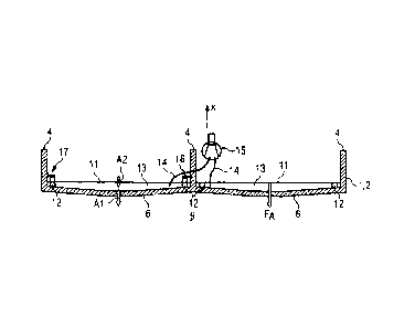
FIG. 2 shows a detail of the side wall 2 of the housing 1 shown
in FIG. lA in the vertical direction (along the z axis), which
is delimited laterally by two reinforcing ribs 4, with a
further reinforcing rib 4 being provided centrally between said
two reinforcing ribs. The side wall 2 is bent slightly inwards
(counter to the x axis) between the reinforcing ribs 4 for
absorbing loads of higher pressures in the interior 9 of the
housing 1. During operation of a transformer accommodated in
the housing 1, in particular an oil-filled transformer, in
which the interior is filled with oil, the side wall 2 vibrates
. CA 02734563 2011-02-17
PCT/EP2008/006917 - 13a -
2008P10623WOUS
owing to transformer hum conducted through the oil. As is
indicated in FIG. 1A and FIG. 1E, the wall 2
, . = CA 02734563 2011-02-17
PCT/EP2008/006917 - 14 -
2008P10623WOUS
is subject to comparatively low vibrations at or in the
vicinity of the reinforcing ribs 4; severe vibrations instead
occur in the plate-like wall regions 6 delimited by the
reinforcing ribs 4, as is indicated by way of example by the
double arrow denoted by Al. The oscillations defining a
generation of sound are perpendicular to the surface of the
plate-like wall region 6 or approximately parallel to the
surface normal thereof. Each of the two plate-like regions 6
shown which are not provided with reinforcing elements is
covered in each case by means of a plate-shaped vacuum panel
11.
The plate-shaped vacuum panel 11 itself represents an
oscillatory system, whose natural frequencies are determined by
its geometry (thickness, length, width), physical properties
(modulus of elasticity, density), the clamping situation and,
in the case of pressure being applied to one side, by resultant
force boundary conditions. The oscillation properties of the
vacuum panel 11 can be determined, for example, by the
Kirchhoff plate theory or the Timoshenko-Mindlin bending wave
equation. The vacuum panel 11 is dimensioned such that there
are no dominant natural modes or resonant frequencies in the
frequency range to be damped. In addition, the thickness of the
vacuum panel 11 is selected such that bending of the vacuum
panel 11 which .results in contact with the plate structure 6
therebelow is avoided by the differential pressure (ambient
pressure/negative pressure in the cavity 13) depending on the
field dimensions and the flexural strength.
The mass of the vacuum panels 11 for sound decoupling is also
much lower than the mass of the plate structures 2, 6 to be
damped which have the same area.
The respective vacuum panel 11 rests, via a negative-pressure-
tight peripheral seal 12, on the region 6 located between the
= = CA 02734563 2011-02-17
PCT/EP2008/006917 - 14a -
2008P10623WOUS
reinforcing ribs 4 and covers said region apart from a small
gap towards the respective reinforcing rib 4. The
: = CA 02734563 2011-02-17
PCT/EP2008/006917 - 15 -
2008P10623W0US
peripheral seal 12 at the same time acts as a spacer between
the plate 6 and the insulation panel 11.
By virtue of the vacuum panel 11, the housing wall 2 and the
circumferential peripheral seal 12, a cavity or interspace 13
is produced between the vacuum panel 11 and the housing wall 2,
which cavity or interspace is connected to a vacuum pump 15
which generates as little noise as possible via a respective
vacuum line 14. In principle, the vacuum pump 15 is connected
in series or in parallel to the cavities 13 to which a negative
pressure is applied. During steady-state operation, the vacuum
pump 15 merely needs to compensate for losses of leak rate; the
design of the vacuum pump 15 can be such that it has
correspondingly small dimensions. Continuous operation of the
vacuum pump 15 is not necessary either if a sufficient negative
pressure within a pressure regulating range is ensured by
pressure regulation.
During operation of the vacuum pump 15, the vacuum panel 11 is
attracted by suction or drawn to the housing wall 2 or the
plate-shaped region 6 with a force FA as a result of the
negative pressure produced in the cavity 13, as is indicated by
the arrow. In this case, the negative pressure is preferably
dimensioned such that the contact-pressure force FA keeps the
vacuum panels 11 safely in the previously positioned location,
counter to all static (for example gravitational force) and
dynamic forces (including operating conditions), depending on
the horizontal or vertical position of said vacuum panels 11.
The negative pressure which is thus set in the cavity 13
therefore firstly ensures a secure fit of the vacuum panel 11
against the housing wall 2, 6 and secondly brings about a
reduction in noise owing to the lower oscillation excitation of
the vacuum panel 11 owing to a sound transmission from the
plate-like region 6 through the cavity 13. In other words, the
lower pressure in
. , CA 02734563 2011-02-17
PCT/EP2008/006917 - 15a -
2008P10623W0US
the cavity 13 reduces the coupling between the vibrating plate
6 and the vacuum panel 11 and improves the sound insulation
effect.
= = = CA 02734563 2011-02-17
PCT/EP2008/006917 - 16 -
2008P10623WOUS
The oscillation damping becomes even more effective by virtue
of the fact that an oscillation excitation of the vacuum panel
11 as a result of a structure-borne noise transmitted via the
fastening 16 to the housing 2, 6 is low since the vacuum seal
12 is comparatively soft and also the fastening of the vacuum
panel 11 is not permanent. Instead, in the event of a reduction
in or failure of the negative pressure, the vacuum panel 11 is
released from the housing 2, 6 without any further measures.
In order to prevent the vacuum panels 11 from falling off the
housing 2, 6 in the event of a desired or undesired loss of
negative pressure, a punctiform negative-pressure loss holder
16 and a linear negative-pressure loss holder 17 are disclosed
here by way of example, said holders catching the vacuum panels
11 in the event of a loss of negative pressure. In this case,
the position and geometry of the holders structurally ensure
that there is no notable transfer of vibrations to the panels
via the holders during normal operation when a vacuum is
applied. In the event of a pressure loss, a residual sound
insulation effect as a result of sound absorption properties of
the panels and the cavity arrangement per se remains.
In order that the vacuum panels 11 do not need to be pressed
individually against the housing again when a negative pressure
is produced again in the cavity 13, but are automatically
attracted to the housing 2 again, the negative-pressure loss
holder 16, 17 is also designed and arranged in such a way that
it presses the vacuum panel 11 gently against the housing 1, 6,
as a result of which the seal 12 retains sufficient
sealtightness.
The cavity 13 to which a negative pressure is applied can also
be equipped with sound-absorbing materials (not shown), for
example with insulation wool and/or porous absorbers.
. CA 02734563 2011-02-17
PCT/EP2008/006917 - 16a -
2008P10623WOUS
In an alternative configuration, for example, various cavities
13 can be fluidically connected to
= = CA 02734563 2011-02-17
PCT/EP2008/006917 - 17 -
2008P10623W0US
one another, with the result that it is not necessary for each
cavity 13 to have a dedicated connection 14 to a vacuum pump
15.
Overall, much less vibration results at a vacuum panel 11 than
in the region to be damped therebelow, as is indicated by the
smaller double arrow A2.
FIG. 3 shows a plan view of two housing regions 6, which are
covered by a respective vacuum panel 11 or cavity 13 and are
delimited laterally by straight ribs 4. The vacuum panels 11
have, in plan view, a rectangular basic shape with rounded-off
edges. The negative-pressure seal 12 present in the form of a
sealing edge 0 ring and having a position which is indicated
here by dashed lines is close to the periphery and follows the
shape of the periphery of the vacuum panel 11. For the right-
hand vacuum panel 11, two types of negative-pressure loss
holders are shown by way of example, namely the "punctiform"
negative-pressure loss holder 16 described already in FIG. 2
and the "linear" negative-pressure loss holder 17.
Figure 4A shows the negative-pressure loss holder 16 or 17 in a
depiction similar to that in figure 2 in the region of the
reinforcing rib 4. The negative-pressure loss holder 16, 17
has, in one configuration, a projection 18 made of metal which
emerges laterally from the reinforcing rib 4 and extends over
the vacuum panel 11. An elastic plastic element ("stopper") 19
is located fastened on the metal and directed towards the
vacuum panel 11 and in a manner so as to press said vacuum
panel 11 against the 0 ring 12.
In the variant shown in figure 4B, the negative-pressure loss
holder 16, 17 no longer emerges from the reinforcing rib 4, but
from the plate-shaped wall region 6, which is delimited by the
, = = . CA 02734563 2011-02-17
PCT/EP2008/006917 - 17a -
2008P10623WOUS
reinforcing rib 4. The negative-pressure loss holder 16, 17
therefore has a metallic holder part 20, which extends
vertically, starting from the region 6, between the vacuum
panel 11 and the reinforcing rib 4 in front of the vacuum panel
11 and is thereafter curved in such a way that it reaches
laterally
= CA 02734563 2011-02-17
PCT/EP2008/006917 - 18 -
2008P10623WOUS
over the vacuum panel 11 from the outside. In this case too,
the plastic stopper 19 is provided on the metallic holder part
20. In the event of a loss of negative pressure, the vacuum
panel 11 presses harder against the stopper and thus increases
the distance from the plate region 6. However, the vacuum panel
11 is not lifted off from the seal 12, but merely relieves the
stress on said seal 12, with the result that a negative
pressure can build up again thereafter, which negative pressure
draws the vacuum panel 11 automatically against the plate
region 6.
Figure 5A shows the arrangement of the wall region 6, the seal
12, the vacuum panel 11 and the cavity 13 on a peripheral
region of the vacuum panel 11 in a further detailed
illustration, wherein the negative-pressure-proof sealing ring
12 is in the form of a hose-like seal. In order to physically
fix the seal 12, the vacuum panel 11 has an accommodating
groove 21 for partially accommodating the seal 12 on its side
directed towards the housing 2. In an alternative
configuration, the receptacle 21 can also be provided in the
housing 2, or both in the housing 2 and in the vacuum panel 11.
Figure 5B shows a further embodiment of the vacuum panel 22,
which now has a multilayered design (in the form of a sandwich
structure) with a plurality of vacuum chambers 24 which are
dependent on one another or insulated from one another. In this
case, two panel layers (support layers) 23 which are spaced
apart from one another are now separated from one another by a
cavity 24, to which a negative pressure is applied, wherein the
cavity 24 is sealed off on the other side by a further vacuum
seal 12. In this case, the negative pressure in the cavity 24
of the vacuum panel 22 can be produced by a dedicated fluid
line to a vacuum pump or, for example, by virtue of the fact
that the cavity 24 is fluidically connected to the cavity 13,
to which a negative pressure can be applied, between the
' = ' CA 02734563 2011-02-17
PCT/EP2008/006917 - 18a -
2008P10623W0US
negative-pressure panel 22 and the housing 2, for example by
means of one or more leadthroughs. This embodiment can also be
referred to as a "double vacuum panel" since it can in
principle also be described as an arrangement of two vacuum
panels or panel layers 23 stacked one on top of the other. It
is
i = CA 02734563 2011-02-17
PCT/EP2008/006917 - 19 -
2008P10623W0US
of course possible for the type and shape of the panels 23 to
differ from the type and shape of the panels 11 shown in
figures 1 to 5A. It is also possible for more than two panel
layers or panels to be arranged one above the other in order
thus to produce an n-layered vacuum panel with improved noise
insulation, where n 3.
If sheet steel or aluminum is used for the vacuum panels or
panel layers, these materials do not demonstrate any notable
inner damping; structure-borne noise can propagate virtually
unimpeded in the plate and be emitted over a large area as
airborne noise. In order to increase the damping of the panels,
at least one damping sound absorber layer, for example a
plastic lining, can be applied to the panel (two-layered
composite sheet) or an absorber layer, in particular damping
plastic layer, can be introduced between two cover sheets
(three-layered composite sheet), for example at least on one
side. The damping effect of such and similar composite sheets
consists in that the pulsating deformations are forced upon the
damping plastic layer in the event of bending oscillations of
the sheet, as a result of which oscillation energy is absorbed
there owing to inner friction.
Figure 6 shows, in this regard, a possible further embodiment
of a vacuum panel 25 with a three-layered embodiment, wherein
there is now no cavity between two metallic support layers 23
of the vacuum panel 25, but a sound-absorbing interlayer 26.
For particularly effective dissipation of vibration energy into
heat, the interlayer 26 has a viscoelastic plastic. In the
exemplary embodiment shown here, the thickness of the plastic
interlayer 26 is between 25 pm and 50 pm.
In principle, it is possible for even more alternate
interlayers 26 and cover layers 23 to be provided, for example
= = CA 02734563 2011-02-17
PCT/EP2008/006917 - 19a -
2008P10623W0US
two viscoelastic interlayers 26 which are inserted between
three metallic panel layers 23, or more generally
CA 02734563 2011-02-17
PCT/EP2008/006917 - 20 -
2008P10623WOUS
n sound-absorbing interlayers 26, in particular viscoelastic
interlayers, which are introduced between n+1 metallic panel
layers (support layers) 23, or else alternately n absorber
layers and n support layers, or else n support layers which are
introduced between n+1 sound-absorbing interlayers 26.
Instead of metallic support layers, support layers with or
consisting of plastic and/or ceramic can also be used.
These vacuum panels 25 can be used instead of the vacuum panels
22 shown in figure 5B or else instead of only one panel layer
23 shown in figure 5B.
The present invention is of course not restricted to the
exemplary embodiments described.
Thus, the plate structure to be damped can generally be
provided on one side with a dense fluid (for example with oil
in the case of a housing for an oil-filled transformer or water
in the case of a tank structure), or else not.
The vacuum panels can be arranged on the front and/or rear side
of a plate structure to be damped.
The vacuum panels can be fitted retrospectively to already
existing reinforced plate structures.
The device is not restricted to a transformer housing, but can
also be in the form of a housing for motors etc., for example.
CA 02734563 2011-02-17
PCT/EP2008/006917 - 21 -
2008P10623WOUS
List of reference symbols
1 Housing
2 Side wall
3 Side wall
4 Reinforcing rib
Open upper side
6 Wall regions susceptible to vibrations
7 Placement line
8 Support
9
11 Vacuum panel
12 Peripheral seal
13 Cavity
14 Vacuum line
Vacuum pump
16 Negative-pressure loss holder
17 Negative-pressure loss holder
18 Projection
19 Stopper
Holder part
21 Receptacle
22 Vacuum panel
23 Panel layer
24 Cavity
Vacuum panel
26 Deformable interlayer
Amax Vibration amplitude maximum
Amin Vibration amplitude minimum
FA Contact-pressure force