Note: Descriptions are shown in the official language in which they were submitted.
CA 02734602 2011-02-17
WO 2010/024745 PCT/SE2008/050975
1
A WAVE-POWER UNIT, AND A USE OF A SUCH
Field of invention
The present invention in a first aspect relates to a wave-power unit for the
production of electric power and comprising a floating body arranged for
floating
on the sea and an electric linear generator having a stator and translator
reci-
procating along a center axis, the stator being arranged to be anchored in the
bed
of a sea and the translator being connected to the floating body by connection
means, which translator is journalled in a plurality of rolling elements such
that a
io circumferential gap is formed between the stator and the translator,
In a second aspect the invention relates to a use of such a wave-power
unit.
In the present application the terms "axial", "radial" and "circumferential"
refer to the axes defined by the reciprocating movement of the centre of the
translator if not explicitly stated otherwise. The terms "upper" and "'lower"
refer to
the vertical direction and relates to the orientation of the components in
question
when the wave-power unit is in operation.
Background of the invention
Wave movements in the sea and in large inland lakes constitutes a poten-
tial source that have scarcely been exploited so far. However various
suggestions
have been made to use the vertical movements of the sea for producing
electrical
power in a generator. Since a point on the sea surface makes a reciprocating
vertical movement it is suitable to use a linear generator to produce the
electric
power.
WO 2004/085842 discloses such a wave-power unit where the moving
part of the generator, i.e. the part that corresponds to the rotor in a
rotating gene-
rator and in the present application called translator, reciprocates in
relation to the
stator of the generator. In that disclosure the stator is anchored in the sea
bed,
The translator is by wire, cable or a chain connected to a body floating on
the sea.
It is important that the guiding of linear motion of the translator in
relation
to the stator is exact and reliable so that the size of the gap between the
translator
and stator is retained at an exact value. The gap is in the size of I - 5 mm,
prefe-
rably about 2 mm. Since a generator of the type in question may be fairly
large,
CA 02734602 2011-02-17
WO 2010/024745 PCT/SE2008/050975
2
insufficient precision in the guiding entails that the size of the gap risks
deviating
substantially from the predetermined one. This entails asymmetry of the
occurring
magnetic forces, which results in harmful asymmetric forces on the translator
with
the risk of operational disturbances as well as breakdown. Also the electro-
s magnetic transformation of energy is effected negatively by erroneous gap
size.
Between the translator and the stator there are very strong magnetic
attraction forces. In order to minimize the load on the bearings therefore the
generator preferably is made symmetrical such that the magnet force across the
gap on one side outbalances the magnet forces across the gap on an opposite
io side. The journaling force required thereby is ideally zero.
However when there occurs a slight deviation from the equilibrium the
magnet forces on the side where the gap decreases will increase and on the
opposite side where the gap increases the magnet forces will decrease. Thereby
a
resultant magnetic force will act to further move the translator towards the
side
1s where the gap is decreased.
The object of the present invention is to arrange the journaling of the
translator such that the above described effect that occurs when the gap width
changes is counter-acted in an effective way.
20 Summary of the invention
The object of the invention is achieved in that a wave-power unit of the
kind initially specified includes the specific features that each rolling
element has
an elasticity that is low enough to meet the condition that a change in the
width of
the gap results in a change in the total force from the rolling elements on
the
25 translator that is larger than the total magnet forces on the translator
resulting from
said change in width.
The forces from the rolling elements thereby increase more rapidly than
the magnet forces when the gap decreases. The tendency that the decrease of
the
gap width will accelerate due to the increasing magnet forces thereby is
eliminated
30 by the counter-acting forces from the rolling elements.
It is to be understood that the elasticity of the rolling element is the total
journaling elasticity established in the cooperation between the rolling
element and
the tracks against which it rolls. If for example one or both of the tracks on
which
the rolling element rolls has a coating, the elasticity of that coating is
included in
CA 02734602 2011-02-17
WO 2010/024745 PCT/SE2008/050975
3
the elasticity of the rolling element. Likewise is any elasticity in the
mounting of the
rolling element included.
According to a preferred embodiment the change in said total force from
the rolling elements is in the range of 2 to 5 times as large as the change in
said
magnet forces,
Thereby the increase in the forces from the rolling elements is at least
double the increase of the magnet forces, which provides a large reliability
in the
securing of a sufficient counter-acting force. The upper limit of the range
means
that the rolling elements will have a certain minimum elasticity. If these
elements
io were almost completely rigid problems of other kind could occur due to the
high
precision in tolerances that would be required in order to avoid non-uniform
pressure on the various rolling elements.
According to a further preferred embodiment each rolling element has a
shaft mounted on the generator.
This is a mechanically advantageous arrangement that provides a well
controlled cooperation between the rolling elements and the relatively moving
parts.
According to a further preferred embodiment the shafts are mounted on
the translator.
This simplifies to attain an adequate mounting of the rolling elements.
If repair work has to be done regarding the journaling, e.g. exchange of
rolling
elements or adjusting the mounting thereof it is more convenient if they are
mounted on the translator.
According to a further preferred embodiment each rolling element is
preloaded.
This contributes to obtain a proper journaling of the translator in the
neutral position and provides advantageous force conditions when gap width
changes occur.
According to a further preferred embodiment the preloading force on each
rolling element is in the range of I to 5 kN.
For most applications a preloading force within this range will be an
adequate balance between the need to have a sufficient preload and to avoid a
too high squeezing of the rolling elements in the neutral position.
CA 02734602 2011-02-17
WO 2010/024745 PCT/SE2008/050975
4
According to a further preferred embodiment each rolling element is a
wheel with a hub made of metal and a roller bed made of plastic.
Thereby the elasticity of the rolling element is within the element itself,
due
to the plastic roller bed. Thus the rolling element does not need to be
elastically
mounted, which would cause large repair costs in case of bearing failure.
Preferably the metal is iron or steel.
According to a further embodiment the rolling elements include a plurality
of rolling elements that are circumferentially distributed such that the
translator is
journalled in two perpendicular directions.
This allows having the magnet poles circumferentially distributed at more
than two sides of the translator thereby obtaining a higher number of electro-
magnetically energy transferring units.
According to a further preferred embodiment the translator has a main
cross sectional shape perpendicular to the axis that is a polygon, whereby
magnets are provided on each side of the polygon.
A large number of magnets thereby can be provided, and the outbalancing
of the magnet forces in the neutral position of the translator is easy to
obtain. The
polygon shape also provides a well-defined journaling in all directions.
Preferably
the polygon is a regular polygon, which provides a high degree of symmetry
leading to a smooth performance,
According to a further preferred embodiment the polygon is a quadrangle.
In many aspects this leads to a simple and reliable construction of the
generator. Preferably the quadrangle is a square.
According to a further preferred embodiment the translator is arranged to
reciprocate inside the stator, the rolling elements are located on the outside
of the
translator and are mounted at the corners of the polygon.
An internal arrangement of the translator is advantageous in many
respects such as the protection against the environment, the journaling and
the
electric connections to the stator. By locating the rolling elements on the
outside of
the translator they can co-operate directly with the stator which secure a
precise
journaling. Mounting the rolling elements at the corners of the polygon
results in
the most stable journaling, and the sides of the polygon need not to be partly
occupied by rolling elements but will be entirely free for the magnets.
CA 02734602 2011-02-17
WO 2010/024745 PCT/SE2008/050975
According to an alternative preferred embodiment the translator has an
axial through-hole, a rigid element extends through the through-hoe and the
rolling elements are located in the through-hole.
In some applications such an internal journaling leads to a higher precision
s and a less complicated structure, in particular when the cross-sectional
shape of
the translator derivates from a quadrangle. The through-hole is preferably
located
in the center of the translator and the rigid element is preferably
symmetrically
located in relation to the through-hole. The rigid element might constitute
the stator
or be a beam rigidly connected to an externally located stator.
According to a further preferred embodiment the rolling elements include a
plurality of rolling elements located in a common plane perpendicular to the
axis.
The balancing of the mechanical and magnetic forces thereby is
optimized.
According to a further preferred embodiment the rolling elements are
1.5 located in a plurality of such planes where a plurality of rolling
elements is located
in each plane.
Having more than one such plane further secures the force balancing
since the journaling takes place at a plurality of axial positions. Tilting
tendencies
of the translator thereby is eliminated in a simple way.
According to a further preferred embodiment the rolling elements include a
plurality of axially distributed rolling elements.
Also with this embodiment the journaling takes place in different axial
positions securing an axial alignment of the translator in relation to the
stator.
According to a further preferred embodiment the axially distributed rolling
2 elements include a plurality of axial rows of rolling elements, each row
including a
plurality of rolling elements.
Thereby a particularly well-defined journaling is achieved which in a simple
way secures the relation between the translator and stator in all directions.
According to a further preferred embodiment the number of rows is eight,
each row includes 4 to 6 rolling elements and the rolling elements are located
in
groups of eight in a respective plane perpendicular to the axis.
This means that the rolling elements will be located in a matrix axially and
circumferentially. The large number of rolling elements in each row and in
each
plane provides a high spread of the mechanical forces such that each rolling
CA 02734602 2011-02-17
WO 2010/024745 PCT/SE2008/050975
6
element only carries a small part of the total load. This contributes to a
smooth and
reliable performance. Normally 6 to 10 rolling elements in each row is
appropriate.
According to a further preferred embodiment the number of elements is
larger than the number of poles in the generator.
Also with this embodiment a high spread of the mechanical forces is
obtained.
The invention also relates to an electric network connected to at least one
wave-power unit according to the present invention.
According to the second aspect of the invention a wave-power unit
io according to the invention and in particular to any of the preferred
embodiments
thereof is used for generating electric energy for supply to an electric
network,
The invented use has advantages corresponding to those of the invented
wave-power unit and the preferred embodiments thereof, which advantages have.
been described above.
11 The invention will be further described by the following detailed
description
of examples thereof with reference to the accompanying drawings.
Brief description of drawings
Fig, 1 is a schematic section through a wave-power unit according to the
?? invention.
Fig 2 is a section along line 11- II in fig 1.
Fig, 3 is a simplified perspective view of one corner of the translator in fig
2.
Fig. 4 is a simplified section through one of the rolling elements of the
translator
in fig 3.
25 Fig. 5 is a diagram showing the resultant magnet force from one pole as a
function of change in gap width.
Fig. 6 is a diagram showing the wheel force as a function of change in gap
width.
Fig. 7 is a diagram showing the various forces acting on the translator as a
function of change in gap width.
30 Fig. 8 is a section similar to that of Fig. 2 but illustrating an
alternative example.
Description of examples of the invention
Fig. 1 is a schematically side view of a wave-power unit according to the
invention in operation in the sea. A floating body 1 floats on the sea surface
and is
CA 02734602 2011-02-17
WO 2010/024745 PCT/SE2008/050975
7
connected by a connection means 3, 7, to a linear generator 2 anchored at the
sea
bed. The connection means consists of an upper part 3, which is a wire, rope,
chain or the like and a lower part 7 which is a rigid rod. The wire 3 is
connected to
the rod 7 by a joint 13. In the figure the generator is attached at the sea
bed. It is,
however, to be understood that the generator can be located above the sea bed
and be anchored in some other way.
The linear generator 2 has a stator 5 with windings and a translator 6 with
magnets. The translator 6 is able to reciprocate up and down within the stator
5
thereby generating current in the stator windings, which current by an
electric
cable 11 is transferred to an electric network.
When the floating body 1 due to the wave movements of the sea surface
is forced to move up, the floating body will pull the translator 6 down
upwards.
When the floating body thereafter moves down the translator 6 will move down
through gravity.
is Optionally but preferably a spring (not shown) or the like acting on the
translator 6 provides an additional force downwards.
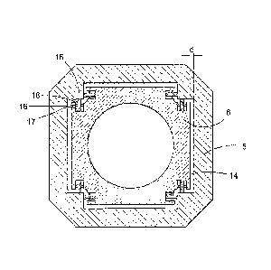
Fig. 2 is a section along line II -- tt in fig I and illustrates the
journaling of
the translator 6 in the stator 5. In the shown example the translator 6 has a
square-shaped cross section. Magnets are provided on all four sides of the
square. Each side of the translator 6 forms a gap 14 with the stator, In the
neutral
position the gap width d is the same on two opposite sides, and preferably the
same on all four sides. To maintain the neutral position as far as possible
the
translator 6 is journalled in a number of rolling elements 15, in the
disclosed
example in the form of wheels. Eight such wheels are provided in a single
cross
sectional plane. Two wheels 15 are arranged at each corner of the translator.
The two wheels 15 at each corner are rotateably mounted on a respective
shaft 16 supported by the translator and the shafts are perpendicular to each
other. Each wheel 15 rolls against a track 17 on the translator 6 and a track
18 on
the stator. Each wheel has a certain elasticity and is somewhat compressed in
order to obtain a preloading force in the neutral position of the translator.
In fig. 3 the arrangement of the wheels is illustrated in a perspective view
towards the left bottom corner of the translator in fig. 2. In the
longitudinal direction
the wheels 15 are arranged in eight rows (two at each corner). In the
illustrated
example the number of wheels in each row is eight, making a total of 64
wheels.
CA 02734602 2011-02-17
WO 2010/024745 PCT/SE2008/050975
8
Fig. 4 illustrates one of the wheels 15 arranged between the track 18 of
the stator 5 and the track 17 on the translator. Fyw1 represents the sum of
all forces
from the }wheels on this side of the translator and FM, represents the sum of
all
magnet forces across the gap on this side.
When the translator is in its neutral position the magnet forces on one side
are outbalanced by the magnet forces on the opposite side so that the
resultant
magnet force on the translator is zero. In that position also the preloading
force
from the wheels outbalance each other.
If the position of the translator is changed from the neutral position such
to that the gap increases on one side and decreases on the other side the
resultant
magnet force will no longer be zero. Within a limited range, i.e. less than I
rmm
change in gap width the magnet force increases approximately linear with
decreasing gap width.
2
CA 02734602 2011-02-17
WO 2010/024745 PCT/SE2008/050975
9
List of symbols used in the following
X decrease of a gap from neutral position
FM = resultant of all magnetic forces across to opposite gaps
F. = sum of all magnetic forces across the gap on the first side
Fm, = sum of all magnetic forces across the gap on the opposite side
FM = sum of all magnetic forces across a gap in the neutral position
KM = constant related to the total magnetic force
'v, = resultant of all wheel forces from two opposite sides
to F,. = sum of all wheel forces on the first side
FW2 = sum of all wheel forces on the opposite side
sum of all preloadin forces from the wheels on one side
K m spring constant of all the wheels on one side
f resultant magnetic force from one pair of opposite poles
fns = magnetic force from one pole across the gap on the first side
fõ,, = magnetic force from one pole across the gap on the opposite side
frry magnetic force from one pole across a gap in the neutral position
k,, W constant related to the magnetic force of one pole
f,,, = resultant force from two opposite wheels
f,, = force from one wheel on the first side
f., = force from one wheel on the opposite side
fS = preloading force from one wheel
I,, = spring constant of one wheel
m = number of poles on one side
n = number of poles on one side
CA 02734602 2011-02-17
WO 2010/024745 PCT/SE2008/050975
If the total magnet force across a gap in the neutral position is the force
across a gap that has been decreased X mm from the neutral position will be
.,, = FM. (1 + KMX), and on the opposite side the magnet force will be
FM2 = FM' (1- KMX) The resultant magnetic force will be F. FM, - FM2 = FM 2K
M., X
5 which acts in the direction of the decreased gap.
This force is counteracted by the forces from the wheels. The total forces
F,,,,, from the wheels on one side of the translator in the neutral position
is Fs,
where Fs is the total preloading force on that side. A corresponding
prelcading
force acts on the opposite side such that the resultant force from the wheels
in the
10 neutral position is zero.
If the position of the translator is changed from the neutral position the
force from the wheels on one side increases and the force from the other side
decreases. The change of the total force from the wheels on one side of the
translator is likewise a linear function of the change of the gap width within
a
is limited range. The force from the wheels on the side where the gap
decreases will
be F w = F3 +K X and on the opposite side F,,. = F3 -- K, . The resultant
force
from the wheels on the translator thus will be F.,, = 2KWX. This is valid only
when
F5 > K;X. If Fs is smaller than that, the resultant force from the wheels will
be
F~v =F3 +KwX
The condition prescribed according to the present invention implies that
Fw > FM. Thus W X > 2F,,,KXor K FM .i M
To have a secure margin against that the magnet forces will override the
wheel forces it is preferred that K > 2FMJKM
The force conditions are shown in figures 5 to 7 for a certain example.
In fig. 5 the resultant magnetic force f,, for the two opposite sides of one
pole is given as a function of the deviation from the neutral position
f, = 2f,,,, k ,where 2f,~o , = 1,64kNtmm. fm, is calculated in kN and X in mm.
The total magnet force from n poles thus will be Fm = 1,64 n X kN in this
example.
In fig. 6 the elasticity of a wheel is illustrated where the spring force from
a
wheel is given as a function of the deviation from the neutral position.
CA 02734602 2011-02-17
WO 2010/024745 PCT/SE2008/050975
11
fit f, .+. k, X,where f = 066 kN and k = 7, 8 kN/mm. A wheel on the opposite
side acts with a spring force in the opposite direction which is f = fs _..
k,, X so
that the sum of the forces from the two opposite wheels will be f", 2k W X =
15, 6
X M With m wheels the total force from the wheels will be: F, = 15, 6 m X kN.
Applying the condition that F should be 2F, as a minimum will result in
15,6 m X = 2 -1,64 n. which gives that the number of wheels on one side is:
2.1,64
15:6
In this example the translator has 33 poles which leads to a requirement of
0,21 '33 = 7 wheels on each side. Due to symmetry reasons the wheels are
io arranged in pairs on each side which means that four pair of wheels is
required on
each side in this example, resulting in a total of 32 wheels on the
translator.
The example is further illustrated in the graph of fig. 7, where the forces in
kN are given as a function of change in the gap width, where A is the force
from a
pair of wheels on one side, B is the force from the opposite pair of wheels, C
is the
15 sum of A and B, D is the resultant force from one pole and F is the sum of
C and
D.
The wheels used in the above example have a diameter of 150 mm and a
thickness of 30 mm. They are made of cast iron having a roller bed made of
polyurethane. Each wheel should be able to maintain rolling with a tolerance
of
20 0,25 mm without overloading the wheel bearing and be designed for 108
translator
cycles. A wheel used in the example operate with a force of 5 k for 130
millions
of turns at a speed of 1 rnls with 90% reliability and for 48 millions of
turns with
99% reliability,
Fig. 8 in a section perpendicular to the axial direction schematically
25 illustrates an alternative example, where the translator 6 is internally
jourr tilled.
The translator 6 has an axial through-hole 20 in which a rigid element 19
extends.
The rolling elements 15 operate between the translator 6 and the rigid element
19
to maintain a uniform gap-width between the translator 6 and the stator 5 as
described above. The rigid element 19 is rigidly connected to the stator 5. It
is to
30 be understood that the shape of the through-hole 20 does not necessarily
need to
correspond to the external shape of the translator 6 as in the case in the
figure.