Note: Descriptions are shown in the official language in which they were submitted.
CA 02734862 2011-02-17
WO 2010/022316 PCT/US2009/054589
BAG WITH REINFORCING FEATURES
CROSS REFERENCE TO RELATED APPLICATIONS
[0001] This application claims the benefit of U.S. Provisional Application No.
61/091,143, filed August 22, 2008, which is hereby incorporated by reference
in its
entirety.
BRIEF SUMMARY
[0002] Among their many applications, it is known to use thermoplastic bags as
liners in trash or refuse receptacles. Trash receptacles that employ such
liners can be
found at many locations from small household kitchen garbage cans to larger,
multi-
gallon drums located in public places and restaurants. Bags that are intended
to be
used as liners for such refuse containers are typically made from low-cost,
pliable
thermoplastic material. When the receptacle is full, the thermoplastic liner
actually
holding the trash can be removed for further disposal and replaced with a new
liner.
[0003] It is desirable to reduce the cost of producing the disposable
thermoplastic
bags as much as possible. Therefore, such bags typically are mass-produced in
high
speed manufacturing environments. Other cost savings can be realized by
reducing
the amount or quality of thermoplastic material utilized to make the bag.
However, as
can be appreciated by those of skill in the art, reducing the amount or
quality of
thermoplastic material forming the bag limits bag strength and makes the bag
susceptible to tearing or rupture. Accordingly, there is a need for a
thermoplastic bag
designed in a manner that reduces material cost while maintaining strength and
facilitating high-speed manufacturing.
[0004] A thermoplastic bag may be provided for use as a trash receptacle liner
that includes a reinforcing feature to resist rupture or puncture. In an
embodiment, the
bag may include opposing first and second sidewalls of thermoplastic material
overlaid and joined to each other along a bottom edge to provide an interior
volume
for receiving trash. The sidewalls remain un-joined along a top edge, located
opposite
the bottom edge, to provide an opening for accessing the interior volume. The
reinforcing feature may be a strip of reinforcing material proximate the
bottom edge
and attached thereto. The reinforcing strip provides an added layer for
strengthening
the bag in a region that may be prone to rupture or failure. The reinforcing
strip may
be made of a thinner material, a material of the same thickness, or a thicker
material
1
CA 02734862 2011-02-17
WO 2010/022316 PCT/US2009/054589
than the first and second sidewalls. The reinforcing strip may be made of a
weaker
material, a material of the same strength or a stronger material than the
first and
second sidewalls. In various embodiments, the reinforcing strip may be
inserted into
the interior of the bag and attached proximate the bottom edge, or the
reinforcing strip
may be folded about the exterior proximate the bottom edge.
[0005] A method for the high-speed production of a bag with reinforcing strips
may be provided. The production method utilizes continuous webs and/or strips
of
thermoplastic material that are advanced through various processing equipment
that
processes the webs and/or strips into a plurality of individual finished bags.
Because
the bags are manufactured from continuous webs processed through the
processing
equipment, a high-speed manufacturing environment is achieved with resulting
lowered incremental cost per bag.
[0006] A thermoplastic bag may be provided that includes opposing first and
second sidewalls overlaid and joined to each other along a closed bottom edge
and
sealed side edges to provide an interior volume. The sidewalls remain un-
joined
along a top edge located opposite the bottom edge to provide an opening for
accessing
the interior volume. To provide the reinforcing feature, the thickness of the
first and
second sidewalls is greater proximate the closed bottom edge than the
thickness of the
sidewalls proximate the open top edge. In various embodiments, the first and
second
sidewalls may be made from the same web of thermoplastic material or may be
made
from two separate webs of thermoplastic material that are joined together.
BRIEF DESCRIPTION OF THE DRAWINGS
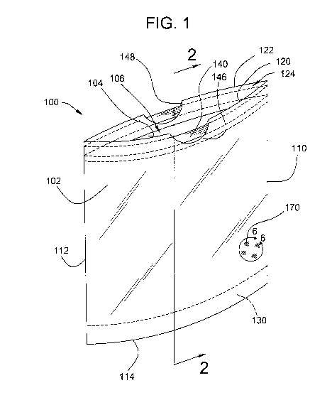
[0007] FIG. 1 is a perspective view of a thermoplastic bag including a
reinforcing
strip inserted into the bag proximate the bottom edge of the bag.
[0008] FIG. 2 is a cross-sectional view taken along line 2-2 of FIG. 1
depicting
the reinforcing strip inserted into the bag.
[0009] FIGS. 3A-3D are cross-sectional views of the area indicated in FIG. 2
by
circle 3-3, illustrating embodiments of the thermoplastic bag with the
reinforcing
strip.
[0010] FIG. 4 is a perspective view of another embodiment of the thermoplastic
bag including a reinforcing strip folded about the bottom edge of the bag.
[0011] FIG. 5 is a cross-sectional view taken along line 5-5 of FIG. 4
depicting
the reinforcing strip folded about the bottom edge of the bag.
2
CA 02734862 2011-02-17
WO 2010/022316 PCT/US2009/054589
[0012] FIG. 6 is a perspective view of the area indicated in FIG. 1 by circle
6-6,
illustrating one type of thermoplastic material suitable for the bag and
having a
stretchable or yieldable characteristic, the material being in the un-
stretched condition.
[0013] FIG. 7 is a perspective view similar to that of FIG. 6 illustrating the
thermoplastic material in a partially-stretched condition.
[0014] FIG. 8 is a schematic view of a thermoplastic bag processing
environment
for the production of bags having reinforcing strips wherein the reinforcing
strip is
attached to a web prior to folding the web.
[0015] FIG. 9 is a schematic view of another embodiment of the bag processing
environment wherein the folded reinforcing strip is inserted into a folded
web.
[0016] FIG. 10 is a top plan view of the bag processing environment of FIG. 9
illustrating the folded reinforcing strip being inserted into the folded web.
[0017] FIG. 11 is a schematic view of another embodiment of the bag processing
environment wherein the reinforcing strip is folded over a folded web.
[0018] FIG. 12 is a front plan view of the environment of FIG. 11
schematically
illustrating a first processing step for reinforcing the web with the
reinforcing strip.
[0019] FIG. 13 is a front plan view of the environment of FIG. 11
schematically
illustrating a second processing step for reinforcing the web with the
reinforcing strip.
[0020] FIG. 14 is a front plan view of the environment of FIG. 11
schematically
illustrating a third processing step for reinforcing the web with the
reinforcing strip.
[0021] FIG. 15 is a schematic view of another embodiment of a bag processing
environment in which the bag is produced from first and second webs each
having a
reinforcing portion.
[0022] FIG. 16 is a cross-sectional view taken along line 16-16 of FIG. 15
showing the construction of the processed bag.
[0023] FIG. 17 is a top plan view of another embodiment of a bag processing
environment wherein a folded web is partially separated and a reinforcing
strip is
inserted into the separated web.
[0024] FIG. 18 is a cross-sectional view taken along line 18-18 of FIG. 17
illustrating the arrangement of the separated web and reinforcing strip within
the bag
processing environment.
[0025] FIG. 19 is a cross-sectional view taken along line 19-19 of FIG. 17.
[0026] FIG. 20 is a top plan view of another embodiment of a bag processing
environment wherein a folded web is partially separated by a V-shaped plate
and a
reinforcing strip is inserted into the separated web.
3
CA 02734862 2011-02-17
WO 2010/022316 PCT/US2009/054589
[0027] FIG. 21 is a cross-sectional view taken along line 21-21 of FIG. 20
illustrating the arrangement of the separated web and reinforcing strip within
the bag
processing environment.
[0028] FIG. 22 is a cross-sectional view taken along line 22-22 of FIG. 20.
[0029] FIG. 23 is a schematic diagram of a bag processing environment with
multiple production steps or stages including the step of attaching a
reinforcing strip
to a web to provide a reinforced thermoplastic bag.
[0030] FIG. 24 is a front elevational view of an embodiment of a thermoplastic
bag having a reinforcing strip wherein a portion of the bag has been provided
with the
strainable network illustrated in FIGS. 6 and 7.
[0031] FIG. 25 is a schematic view illustrating a processing environment for
producing both a thermoplastic web and a reinforcing strip from the same
material.
[0032] FIG. 26 is a cross-sectional view similar to that of FIG. 2 depicting a
thermoplastic bag having a reinforced bottom edge made from a single extruded
web.
[0033] FIG. 27 is a cross-sectional view similar to that of FIG. 2 depicting a
thermoplastic bag having a reinforced bottom edge made from first and second
extruded webs joined together.
DESCRIPTION
[0034] Referring to FIG. 1, there is illustrated an embodiment of a flexible
bag
100. While flexible bags are generally capable of holding a vast variety of
different
contents, the specific bag 100 illustrated in FIG. 1 may be used as a liner
for a
garbage can or similar refuse container. The bag 100 may be made from a first
sidewall 102 and an opposing second sidewall 104 overlying the first sidewall
to
provide an interior volume 106 therebetween. The first and second sidewalls
102,
104 may be joined along a first side edge 110, a parallel or non-parallel
second side
edge 112, and a closed bottom edge 114 that extends between the first and
second side
edges. The sidewalls 102, 104 may be joined along the first and second side
edges
110, 112 and bottom edge 114 by any suitable process such as, for example,
heat
sealing.
[0035] For accessing the interior volume 106 to, for example, insert refuse or
garbage, the top edges 120, 122 of the first and second sidewalls 102, 104
remain un-
joined to define an opening 124 located opposite the closed bottom edge 114.
When
placed in a trash receptacle, the top edges 120, 122 of the first and second
sidewalls
102, 104 may be folded over the rim of the receptacle.
4
CA 02734862 2011-02-17
WO 2010/022316 PCT/US2009/054589
[0036] The first and second sidewalls 102, 104 may be made of flexible or
pliable
thermoplastic material formed or drawn into a smooth, thin-walled web or
sheet.
Examples of suitable thermoplastic material may include polyethylenes, such
as, high
density polyethylene, low density polyethylene, linear low density
polyethylene,
polypropylene, ethylene vinyl acetate, nylon, polyester, ethylene vinyl
alcohol,
ethylene methyl acrylate, or other materials and may be formed in combinations
and
in single or multiple layers. When used as a garbage can liner, the
thermoplastic
material may be opaque but in other applications may be transparent,
translucent, or
tinted. Furthermore, the material used for the sidewalls may be a gas
impermeable
material.
[0037] To strengthen the bag 100 in order to reduce rupture or puncture, the
bag
may include a reinforcing feature in the form of a reinforcing strip 130
proximate and
attached to the bottom edge 114 of the bag. In the illustrated embodiment, the
reinforcing strip 130 may be inserted into the interior volume 106 between the
first
and second sidewalls 102, 104. The reinforcing strip 130 may extend between
the
first and second side edges 110, 112 to be coextensive with the bottom edge
114.
Referring to FIG. 2, the reinforcing strip 130 thereby provides an extra layer
of
material in a region of the bag 100 that may be prone to failure because
gravity directs
the weight of the contents against the bottom edge 114. This region may be
prone to
failure because, when replacing liners in a trash receptacle, a user may grasp
the bag
100 about its opening 124 and may drag the bag along the floor or ground
causing
wear to the bottom edge 114.
[0038] The reinforcing strips 130 may be made from any suitable, thermoplastic
material including, for example, polyethylenes, such as, high molecular weight
high
density polyethylene high density polyethylene, low density polyethylene,
linear low
density polyethylene, polypropylene, ethylene vinyl acetate, nylon, polyester,
ethylene vinyl alcohol, ethylene methyl acrylate, or other materials and can
be formed
in combinations and in single or multiple layers. In various embodiments, the
material of the reinforcing strip may have a higher strength and abrasion
resistance
than the material of the bag sidewalls 102, 104. Making the reinforcing strip
of
stronger and/or tougher material may help further protect the bag against
rupture
and/or puncture.
[0039] The reinforcing strip 130 may be formed as a separate, elongated
rectangular strip of material that may be attached to the bottom edge.
Referring to
FIG. 2, the rectangular reinforcing strip 130 may be folded in half along its
length to
form a first half portion 132 and a second half portion 134. The folded
reinforcing
CA 02734862 2011-02-17
WO 2010/022316 PCT/US2009/054589
strip 130 may be inserted into the interior volume 106, and the first half and
second
half portions 132, 134 may be attached to the respective first and second
sidewalls
102, 104. Attachment of the reinforcing strip and sidewalls may be achieved by
any
suitable means including heat-sealing the materials together or use of
adhesive.
[0040] Referring to FIG. 3A, the sidewall may have a thickness 150. The
thickness 150 may have a first range of about 0.0005 inches (0.0013 cm) to
about
0.0014 inches (0.0036 cm), a second range of about 0.0006 inches (0.0015 cm)
to
about 0.001 inches (0.0025 cm), and a third range of about 0.0007 inches
(0.0018 cm)
to about 0.00085 inches (0.0021 cm). In one embodiment, the thickness 150 may
be
about 0.0008 (0.0020 cm). The strip 130 may have a thickness 152. The
thickness
152 may have a first range of about 0.0001 inches (0.00025 cm) to about 0.0006
inches (0.0015 cm), a second range of about 0.00025 (0.00064 cm) to about
0.0005
inches (0.0013 cm), and a third range of about 0.00035 inches (0.00089 cm) to
about
0.00045 inches (0.0011 cm). In one embodiment, the thickness 152 may be 0.0004
inches (0.001 cm).
[0041] Referring to FIGS. 3B-3D, to facilitate attaching the reinforcing strip
130
to the sidewalls of the bag, in various embodiments the reinforcing strip
and/or the
sidewalls may be made as a multilayered structure. Referring to FIG. 3B, the
strip
130 may include a first layer 156, a second layer 157 and a third layer 158.
The first
layer 156 and third layer 158 may include polyethylenes (such as, low density
polyethylene, or very low density polyethylene), ethylene vinyl acetate and
ethylene
methyl acrylate, or other material. The second layer 157 may include
polyethylenes,
such as, high density polyethylene, linear low density polyethylene, high
molecular
weight high density polyethylene, low density polyethylene or other material.
The
sidewalls 102, 104 may include a first layer 160, a second layer 161, and a
third layer
162. The first layer 160 and the third layer 162 may include polyethylenes
(such as,
low density polyethylene, or very low density polyethylene), ethylene vinyl
acetate
and ethylene methyl acrylate, or other material. The second layer 161 may
include
polyethylenes, such as, high density polyethylene, linear low density
polyethylene,
high molecular weight high density polyethylene, low density polyethylene or
other
material. The first layer 156 of the strip 130 may directly contact the first
layer 160 of
the sidewall. If the first layer 156 of the strip is the same as or compatible
with the
first layer 160 of the sidewall, then the first layer 156 may bond better with
the first
layer 160.
[0042] The thickness 164 of the multilayer sidewall 130 may be the same as
thickness 150 of the single layer sidewall 102 as noted above. The thickness
166 of
6
CA 02734862 2011-02-17
WO 2010/022316 PCT/US2009/054589
the multilayer strip 130 may be the same as the thickness 152 of the single
layer insert
130 as noted above. The thickness of the first and third layers 160, 162 may
be a
weight percentage of the thickness 164 of the sidewall. The combined weight
percentage of the first and third layers 160, 162 may have a first range of
about I% to
about 99%, a second range of about 15% to about 75%, and a third range of
about
30% to about 50%. In one embodiment, the combined weight percentage of the
first
and third layers 160, 162 may be about 40%, so that the first layer 160 is
about 20%,
the second layer 161 is about 60% and the third layer 162 is about 20%. In
other
embodiments, the first layer and the third layer may have different weight
percentage
of thicknesses, such as, the first layer may be 30% and the third layer may be
10%.
The thickness of the first and third layers 156, 158 may be a weight
percentage of the
thickness 166 of the strip. The combined weight percentage of the first and
third
layers 156, 158 may have a first range of about 1% to about 99%, a second
range of
about 15% to about 75%, and a third range of about 30% to about 50%. In one
embodiment, the combined weight percentage of layers 156, 158 may be 40%, so
that
the first layer 156 is about 20%, the second layer 157 is about 60% and the
third layer
158 is about 20%. In other embodiments, the first layer and the third layer
may have
different weight percentage of thicknesses, such as, the first layer may be
30% and the
third layer may be 10%. Referring to FIG. 3C, the single layer sidewall may be
combined with the multilayer strip. Referring to FIG. 3D, the multilayer
sidewall
may be combined with the single layer strip. In other embodiments, the
sidewall
and/or the strip may have two, four, five, six or more layers.
[0043] Referring back to FIG. 2, the first half portion 132 of the reinforcing
strip
130 may extend adjacently along the first sidewall 102 from the closed bottom
edge
114 only part way towards the opening 124 of the bag 100. The bag 100 may have
a
height 138 measured between the closed bottom edge 114 and opening 124. The
first
half portion 132 may have a height 139 measured from the closed bottom edge
114
toward the opening 124. The height 138 may have a first range of about 20
inches
(50.8 cm) to about 48 inches (121.9 cm), a second range of about 23 inches
(58.4 cm)
to about 33 inches (83.8 cm), and a third range of about 26 inches (66 cm) to
about 28
inches (71.1 cm). In one embodiment, the height 138 may be 27.375 inches (69.5
cm). The height 139 may have a first range of about 1 inches (2.54 cm) to
about 10
inches (25.4 cm), a second range of about 3 inches (7.6 cm) to about 8 inches
(20.3
cm), and a third range of about 4 inches (10.2 cm) to about 6 inches (15.2
cm). In one
embodiment, the height 139 may be 5 inches (12.7 cm). As illustrated, the
second
half portion 134 may extend along the second sidewall 104 a similar distance.
As will
7
CA 02734862 2011-02-17
WO 2010/022316 PCT/US2009/054589
be appreciated, because the reinforcing strip only extends over a portion of
the
sidewalls, the reinforcing strip comprises significantly less material than
the
sidewalls. Thus, the reinforcing strip saves material by using the reinforcing
strip in
the desired area. In addition, this may be beneficial when the reinforcing
strip may be
made from higher strength, more expensive materials by focusing a minimal
amount
of these materials at the location of optimal utilization.
[0044] Referring now to FIGS. 4 and 5, there is illustrated another embodiment
of
the thermoplastic bag 200 including a reinforcing strip 230. The bag 200 may
include
a first sidewall 202 overlaid and joined to a second sidewall 204 to provide
an interior
volume 206. The first and second sidewalls 202, 204 may be joined along a
first side
edge 210, a spaced apart second side edge 212, and a closed bottom edge 214
extending between the first and second side edges. To access the interior
volume 206,
the top edges 220, 222 of the respective first and second sidewalls remain un-
joined to
provide an opening 224.
[0045] To reinforce the bottom edge 214 against rupture and puncture, a
reinforcing strip 230 may be attached to bag 200. In the illustrated
embodiment, the
reinforcing strip 230 may be attached to the exterior of the bag 200 and may
extend
along the bottom edge 214 from the first side edge 210 to the second side edge
212.
The reinforcing strip 230 may be made as an elongated rectangular strip that
may be
folded in half along its length about the bottom edge 214 such that a first
half portion
232 may extend adjacent the exterior surface of the first sidewall 202 and a
second
half portion 234 may extend adjacent the exterior surface of the second
sidewall 204.
Accordingly, in the present embodiment, the reinforcing strip may be located
on the
exterior of the bag in contrast to the embodiment illustrated in FIGS. 1 and 2
wherein
the reinforcing strip may be located on the interior of the bag. The
reinforcing strip
230 provides an additional layer of material along the bottom edge 214.
Additionally,
the first half portion 232 and second half portion 234 may extend only
partially
toward the open top 224 so that the additional material is strategically
placed in an
area prone to failure. The reinforcing strip may have the dimensional ranges
noted
herein. In various embodiments, the reinforcing strip 230 may be made of a
material
having higher strength and abrasion characteristics than the material of the
sidewalls
202, 204 as noted herein. Additionally, the reinforcing strip may be made of
single or
multiple layers as noted herein.
[0046] In addition to the reinforcing strip, the bag may include other
features that
facilitate its use as a liner for trash receptacles. For example, referring
back to FIGS.
1 and 2, to close the opening 124 of the bag 100 when, for example, disposing
of the
8
CA 02734862 2011-02-17
WO 2010/022316 PCT/US2009/054589
trash receptacle liner, the bag may be fitted with a draw tape 140. To
accommodate
the draw tape 140, referring to FIG. 2, the first top edge 120 of the first
sidewall 102
may be folded back into the interior volume 106 and may be attached to the
interior
surface of the sidewall to form a first hem 142. Similarly, the second top
edge 122 of
the second sidewall 104 may be similarly folded back into the interior volume
and
may be attached to the second sidewall to form a second hem 144. The draw tape
140, which may be fixedly attached at the first and second side edges 110,
112,
extends along the first and second top edge 120, 122 loosely through the first
and
second hems 142, 144. To access the draw tape 140, first and second notches
146,
148 may be disposed through the respective first and second top edges 120,
122.
Pulling the draw tape 140 through the notches 146, 148 will constrict the top
edge
120, 122 thereby closing the opening 124. The draw tape closure may be used
with
any of the embodiments herein, as appropriate.
[0047] Referring back to the embodiment illustrated in FIGS. 4 and 5,
different
closing mechanisms such as tie flaps 260, 262 may be employed to close the
opening
224 of the bag. The tie flaps 260, 262 may be extensions of the top edges 220,
222 of
the respective sidewalls 202, 204 that may be tied together when the bag 200
is
removed from the receptacle and disposed of. The tie flap closure may be used
with
any of the embodiments herein, as appropriate. In addition to tie flaps and
draw-
tapes, other suitable closing mechanisms may include twist ties and mechanical
clips.
Furthermore, for securing the bag to a garbage container, an elastic strip may
be
attached about the opening of the bag which may be folded over so as to
constrict
about the rim of the container. In those embodiments where the bag is intended
for
use in applications besides garbage can liners, other suitable closure
mechanisms may
include interlocking fastening strips, low-tack or peelable adhesive, or
various fold-
top arrangements.
[0048] In further embodiments, the thermoplastic sidewalls of the bag may be
configured to stretch or yield to accommodate cumbersome or bulky objects
and/or to
provide further puncture or rupture resistance. For example, referring back to
FIG. 1,
the thermoplastic sheet material making up the sidewalls 102, 104 may be
formed
with a plurality of patterns 170 that allow the sidewalls to stretch or yield.
Examples
of such patterns and similar features are disclosed in U.S. Patent No.
6,139,185; U.S.
Publication No. 2004/0134923; U.S. Patent No. 6,394,651; U.S. Patent No.
6,394,652; U.S. Patent No. 6,150,647; U.S. Patent No. 6,513,975; or U.S.
Patent No.
6,695,476, each of which are herein incorporated by reference in their
entirety.
9
CA 02734862 2011-02-17
WO 2010/022316 PCT/US2009/054589
[0049] Referring to FIGS. 6 and 7, each pattern 170 may form a "strainable
network" that may include a plurality of first regions 172 and a plurality of
second
regions 174. The second regions 174 may be formed as rib-like elements in the
material of the sidewall such that first regions and second regions appear
bunched or
contracted together in the un-tensioned state illustrated in FIG. 6. When a
pulling
force is applied, as indicted by the arrows 176 in FIG. 7, the second regions
174 are
able to unbend or geometrically deform so that the first and second regions
172, 174
may become substantially coplanar with each other. As will be appreciated,
this
action stretches or elongates the pattern thereby adding to the overall area
of the
sidewall. In addition to accommodating bulky objects, the strainable networks
provide shock dampening when objects are suddenly thrust or dropped into the
bag.
[0050] Manufacturing of a bag with a reinforcing feature may be accomplished
in
a number of different ways. To minimize the incremental costs of the bags,
manufacturing may be accomplished in a high-speed automated process. For
example, referring to FIG. 8, there is illustrated a schematic of an
embodiment for
high-speed automated manufacturing of bags in which the reinforcing strip is
provided internally of the bag; i.e. in the interior volume. In the
illustrated
embodiment, production may begin at a first step 300 by unwinding a web 302 of
thermoplastic sheet material from a roll 304 and advancing the web along a
machine
direction 306. The unwound web 302 may have a rectangular profile including a
width 308 that is perpendicular to the machine direction 306 as measured
between a
first edge 310 and an opposite second edge 312. In other manufacturing
environments, the web 302 may initially be provided in other forms or even
extruded
directly from a thermoplastic production process.
[0051] In a subsequent attachment step 320, a continuous strip 322 of
thermoplastic material intended to become the reinforcing strip may be
advanced
toward the web 302 and may be redirected to proceed in parallel and in step
with the
advancing web along the machine direction 306. The thermoplastic strip 322 may
initially be provided from a roll, like the web, or may be directly extruded.
During
redirection, the strip 322 may be oriented about mid-width of the web 302
between
the first and second edges 310, 312 by a roller 324.
[0052] To facilitate attaching the strip 322 to the web 302, the roller 324
may be
heated. Heating of the thermoplastic material of the strip 322 may transition
the strip
material to a phase or physical state in which it may more readily bond with
the
thermoplastic material of the web 302. Besides or in addition to using a
heated roller
324, hot air 326 may be directed onto the web and/or strip. Additionally, in
some
CA 02734862 2011-02-17
WO 2010/022316 PCT/US2009/054589
embodiments in which the strip 322 is extruded just prior to attachment to the
web,
the strip material may remain at a sufficiently elevated temperature to
readily bond to
the web.
[0053] In a subsequent folding step 330, the web 302 may be folded about its
width 308 and inline with the machine direction 306 to provide adjacent first
and
second folded halves 332, 334. The folding step 330 may cause the second edge
312
to move adjacent to the first edge 310 such that the two edges correspond to
the
opened top edge of the finished bag. The mid-width portion of the web 302 with
the
strip 322 attached thereto may correspond to the reinforced bottom edge
portion of the
finished bag which may move in parallel with the machine direction 306.
Additionally, the folded-over halves 332, 334 of the web 302 correspond to the
first
and second sidewalls of the finished bag.
[0054] Additional processing steps may be applied to produce the finished bag.
For example, in an edging step 340, heat seals 342 may be formed across the
width of
the folded web 302 perpendicular to the machine direction 306 by a heat
sealing
device 344. In a perforating step 350, the heat seals 342 may be perforated
by, for
example, a perforating knife 352. The folded, sealed, and perforated web may
then
wound into a roll 360 for distribution. As can be appreciated, finished bags
362 can
be unwound and detached from the roll 360 for use trash receptacle liners. In
another
embodiment, the web may be folded one or more times prior to the perforating
step.
In another embodiment, the web 302 may be cut into individual bags after the
side
seals 342. The web may be folded one or more times prior to the cutting step.
The
individual bags may be interleaved and may be wound onto a roll.
[0055] Referring to FIGS. 9 and 10, there is illustrated another embodiment of
an
automated manufacturing process for manufacturing the bags with internal
reinforcing
strips. In the illustrated process, the thermoplastic web 400 may be folded
into
adjacent first and second halves 402, 404 that may be joined at a common
bottom
edge 414. The process advances the folded web 400 in a machine direction 406
toward a spreader and attachment assembly 420 such that the bottom edge 414
may be
aligned parallel to the machine direction. The spreader assembly 420 may
include a
depending rigid spreader bar 422 that may extend between the first and second
web
halves 402, 404 proximate the bottom edge 414 thereby spreading the halves
apart.
Just prior to the spreader assembly 420, a continuous strip 430 of
thermoplastic
material may be directed perpendicularly to the machine direction 406 between
the
first and second web halves 402, 404. The strip 430 may be folded lengthwise
to
provide a first strip half 432 and a corresponding second strip half 434. The
folded
11
CA 02734862 2011-02-17
WO 2010/022316 PCT/US2009/054589
strip 430 may be redirected by an appropriately arranged roller 424 or similar
device
to an orientation adjacent the bottom edge 414 running parallel with the
machine
direction. The spreader bar 422 may also spread the first and second strip
halves 432,
434 of the folded strip 430 apart from each other and adjacent to the
respective first
and second web halves 402, 404 of the web 400.
[0056] To attach the first and seconds strip halves 432, 434 of the folded
strip to
the first and second web halves 402, 404 of the web, two opposed rollers 440
may be
provided rearward of the spreader bar 422 with respect to the machine
direction 406.
The rollers 440 may be heated and/or hot air 444 may be applied to the web
and/or
strips. The rollers 440 may be positioned proximately toward the bottom edge
414 of
the web 400. Located between the rollers 440 may be a vertically arranged
separator
plate 442. The separator plate 442 may depend between the first and second web
halves 402, 404 of the folded web 400 proximate to the common bottom edge 414.
The separator plate 442 may be narrower in width than the spreader bar 422.
Accordingly, as the web 400 moves along the machine direction 406 past the
spreader
bar 422 the first and second web halves 402, 404 move towards each other but
are still
separated by the separator plate 442.
[0057] At this stage, it will be appreciated that the first web half 402 and
adjacent
first strip half 432 are both directed between a heat roller 440 and the
separator plate
442 while the second web half 404 and adjacent second strip half 434 are
directed
between the opposite roller 440 and the separator plate 442. The rollers 440
may be
heated and/or hot air 444 may be applied to the web and/or strip. The first
web half
402 and first strip half 432 may be fused together while the second web half
404 and
second strip half 434 may be fused together. Because of the separator plate
442, the
joined first web and strip half and joined second web and strip half may
remain
separate and are joined by the common bottom edge 414. The web 400 can
continue
to be directed along the machine direction 406 for further processing steps to
provide
a finished bag.
[0058] Referring to FIG. 11, there is schematically illustrated another
embodiment of a manufacturing process for applying an external reinforcing
strip 530
about the bottom edge 514 of a plastic bag. According to the process of FIG.
11, a
continuous web 500 may be folded into first and second web halves 502, 504
that are
joined along a common bottom edge 514. Initially, the process may direct the
folded
web 500 along a machine direction 506. The bottom edge 514 may be aligned
parallel to the machine direction 506. An unfolded strip 530 of reinforcing
material
may be oriented to be running in parallel with the folded web 500 proximate
the
12
CA 02734862 2011-02-17
WO 2010/022316 PCT/US2009/054589
bottom edge along the machine direction 506. Orientation of the reinforcing
strip
may be accomplished by redirection members 520 such as rollers, pull-nips or
appropriately arranged static rod-like bars. As depicted in FIG. 12, the
unfolded
reinforcing strip 530 may proceed in parallel with and adjacent to the second
web
halve 504. A portion of the reinforcing strip 530 may extend beyond the bottom
edge
514.
[0059] The reinforcing strip 530 may be folded in half along the machine
direction 506 into first and second strip halves 532, 534 so that the portion
of the strip
that had previously extended beyond the bottom edge 514 may be folded over the
bottom edge. Folding of the reinforcing strip 530 may be accomplished by
another
redirection member 522 such as a roller, a pull-nip or a rigid bar. Referring
to FIG.
13, the portion of the web 500 proximate the bottom edge 514 may be located
between the external folded reinforcing strip 530 with the first web half 502
adjacent
the first strip half 532 and the second web half 504 adjacent the second strip
half 534.
[0060] To attach the reinforcing strip 530 to the web 500, the strip and web
may
be directed along the machine direction 506 between a pair of opposed rollers
540.
The rollers 540 may be heated and/or hot air 544 may be applied to the web
and/or
strip. As illustrated in FIG. 14, the rollers 540 may be arranged to be
proximate the
bottom edge 514 of the web 500 to press the first and second strip halves 532,
534
towards the respective first and second web halves 502, 504. The first and
second
strip halves 532, 534 may be fused to the respective first and second web
halves 502,
504. To prevent the web halves 502, 504 from fusing together, a separator
plate 542
may depend in between the web halves and the rollers 540. The web 500 with the
reinforcing strip 530 attached externally to the bottom edge 514 may then
proceed
along the machine direction 506 for further processing.
[0061] Referring to FIG. 15, there is illustrated another embodiment of a
manufacturing process for producing a thermoplastic bag with a reinforcing
feature
from a plurality of separate webs of material. According to the process, a
first web
602 of thermoplastic may be unwound from a roll 600 of web or sheet material
and
may be directed along a machine direction 606. The web 602 may have a width
608
delineated between first and second edges 604, 605 perpendicular to the
machine
direction 606. To provide a portion of the reinforcing feature, a strip 610 of
thermoplastic reinforcing material, narrower in width than the first web, may
be
directed toward the first web and reoriented to run in the machine direction
606
parallel and adjacent to the second edge 605. The first strip 610 maybe
attached to
the first web 602 by, for example, a pair of rollers 612 which may be heated
and/or
13
CA 02734862 2011-02-17
WO 2010/022316 PCT/US2009/054589
hot air 614 may be applied to the web and/or the strip. In the illustrated
embodiment,
the rollers 612 may be arranged to simultaneously accomplish reorientation and
attachment of the strip to the web.
[0062] A second web 622 of thermoplastic material may be unwound from a
second roll 620 of material and directed toward the first web 602. The second
web
may have a width 628 delineated between first and second edges 624, 625. To
provide another portion of the reinforcing feature, a second strip 630 may be
directed
toward the second web 622 and reoriented to run parallel and adjacent to the
second
edge 625. Reorientation of the strip 630 may be accomplished by an
appropriately
arranged pair of rollers 632. The strip 630 may be attached to the second web
622 by,
for example, the pair of rollers 632 which may be heated and/or hot air 634
may be
applied to the web and/or the strip.
[0063] The second web 622 with the second strip attached 630 may be redirected
to run parallel and adjacent to the first web 602 along the machine direction
606 by a
pair of rollers 640. The first and second webs 602, 622 may be oriented so
that the
first and second strips 610, 630 may be facing toward one another. To attach
the
webs 602, 622 together, the webs may be directed between a pair of rollers 642
that
are arranged proximate the second edge 605, 625 of the respective webs. The
rollers
642 may be heated and/or hot air 644 may be applied to the web 602 and/or web
622.
The second edges 605, 625 of the webs and the corresponding portions of the
first and
second strips 610, 630 may be fused together along second edges 605, 625.
Referring
to FIG. 16, the first and second webs 602, 622 may be joined along the second
edges
605, 625 with the remainder of the webs separable.
[0064] The joined webs 602, 622 may proceed along the machine direction 606
for further processing to produce a finished bag. For example, the webs 602,
622 may
be joined together by intermittent heat seals 650 formed along the web widths
608,
628 by a heat sealing device 652. The webs may be perforated along the heat
seals
650 by a perforating device 654. A finished bag 660 may be detached along the
perforation 655. In another embodiment, the webs may be cut into individual
bags
after the side seals, and the bags may be interleaved and rolled onto a roll,
as
described herein. As noted herein, the web may be folded one or more times
before
the perforating step or cutting step. The finished bag 660 may include
opposing first
and second sidewalls 662, 664 that define an interior volume 666. As will be
appreciated, the opposing first and second sidewalls 662, 664 are the
resulting product
of the first and second webs 602, 622. Likewise, the bottom edge 668 of the
finished
14
CA 02734862 2011-02-17
WO 2010/022316 PCT/US2009/054589
bag 660 may be reinforced by the resulting product of the first and second
strips 610,
630.
[0065] In another embodiment, the process shown in FIGS. 15 and the bag shown
in FIG. 15 may be changed so that the first and second strips 610, 630 may be
located
on the outside of the first and second webs 602, 622 and sidewalls 662, 664.
[0066] Referring now to FIGS. 17-19, there is illustrated another embodiment
of
the step or stage within an automated manufacturing environment in which the
reinforcing strip may be arranged next to and may be attached to a flexible
thermoplastic web or sheet which will be processed into the finished bag. The
web
700, which may be folded into first and second web halves 702, 704 that lay
adjacent
to each other, may be aligned and directed along a machine direction 706
toward a
spreader frame 720. The spreader frame 720, which may be made of various
plastic
or metal bars and plates attached together, may be disposed in between the
folded web
700 so as to partially separate the folded web halves 702, 704 that are
proceeding
along the machine direction 706. The spreader frame 720 may include a bottom
plate
722. As the first and second web halves 702, 704 are separated by the spreader
frame
720, the crease 714 which joins the webs halves and corresponds to the bottom
edge
of the finished bag may move toward and run adjacently along the plate 722. As
shown in FIG. 18, the bottom plate 722 may cause a portion of the web halves
702,
704 to form an attachment portion 723. The attachment portion 723 may be
relatively
flat as it passes over the bottom plate 722.
[0067] Referring to FIGS. 17-19, a strip of reinforcing material 730 may be
directed to the upstream end of the spreader frame 720 where the strip may be
positioned near the attachment portion 723 of the web halves 702, 704. The
strip 730
may further be directed downward toward the bottom plate 722 of the frame 720
where the strip may be aligned with the crease 714 and attachment portion 723,
and
the strip may be redirected to run parallel to the machine direction 706, the
crease 714
and attachment portion 723. Accordingly, in this embodiment as illustrated in
FIGS.
18 and 19, the strip 730 may be located between the attachment portion 723 and
the
bottom plate 722 of the spreader frame 720.
[0068] To attach the reinforcing strip 730 and web 700, the spreader frame 720
may include rollers 724. The rollers 724 may be supported by and disposed
through
the bottom plate 722 downstream along the machine direction 706 from where the
strip is initially introduced between the separated web halves 702, 704. The
rollers
724 may be heated. Second rollers 726 may be located beneath the frame 720 and
opposed to the first rollers 724. The rollers 726 may be heated. The opposing
rollers
CA 02734862 2011-02-17
WO 2010/022316 PCT/US2009/054589
724, 726 may be arranged perpendicular to the machine direction 706. Hot air
727
may be applied to the strip 730 and/or the web 700. Accordingly, when the
rollers
724, 726 are heated and/or the hot air activated, the web material 700 and the
reinforcing strip 730 may bond or heat seal together. In other embodiments,
the
rollers 724 may not be used and the rollers 726 may press against the plate
722
through the reinforcing strip 730 and the web 700 to attach the strip to the
web. In
another embodiment, the hot air 727 may not be used and the rollers may be
heated.
In another embodiment, the hot air may be used and the rollers may not be
heated. In
other embodiments, the processing equipment for attaching the web 700 and
strip 730
may be located further along the machine direction downstream of the folding
frame
720.
[0069] Referring to FIGS. 20-22, there is illustrated another embodiment of a
step
or stage for placing together a flexible thermoplastic web 800 and a strip of
thermoplastic reinforcing material 830 within a high speed manufacturing
environment. The web 800, as initially provided, may be folded lengthwise into
adjacent first and second web halves 802, 804 that may be movingly directed
along a
machine direction 806.
[0070] To separate the adjacent web halves 802, 804, a V-shaped plate 820 made
of a material, such as metal or plastic, may be disposed between the first and
second
webs halves with its inclined peak 821 directed against the machine direction
806.
The V-shaped plate 820 may be made from any suitable material, such as metal
or
plastic, and may include inclining first and second legs 822, 824 that may be
reinforced by support bars 826 arranged to traverse the V-shape. As the web
800 is
directed along the machine direction 806, the V-shaped plate 820 may partially
separate the adjacent first and second web halves 802, 804. Additionally, as
separation of the web halves occurs, the bottom crease 814 which joins the
webs
halves and corresponds to the bottom edge of the finished bag may move toward
and
run adjacently along the bottom of the V-shaped plate 820. As shown in FIG.
21, the
V-shaped plate 820 may cause a portion of the web halves 802, 804 to form an
attachment portion 823. The attachment portion 823 may be relatively flat as
it passes
through the V-shaped plate 820.
[0071] Also after separation of the web halves, a strip of the reinforcing
material
830 may be directed to the V-shaped plate 820 and downward between the
inclined
legs 822, 824 to a point proximate with the crease 814 and the attachment
portion 823
of the web 800. The strip 830 may be redirected by, for example, bars or
rollers 828
to run parallel with the machine direction 806 and parallel and adjacent to
the crease
16
CA 02734862 2011-02-17
WO 2010/022316 PCT/US2009/054589
814 and the attachment portion 823. The strip 830 may be physically attached
to the
web 800 within the extension of the V-shaped plate or downstream. The strip
830
may be attached to the web 800 using heated rollers and/or hot air as noted
herein.
After passing by the V-shaped plate 820, the first and second web halves 802,
804
may be folded adjacent to each other about the crease 814.
[0072] In addition to the step or stage of aligning and/or attaching the
reinforcing
strip to the thermoplastic web, the manufacturing environment may include any
number of additional processing steps or stages for producing a finished bag.
Referring to FIG. 23, there is illustrated schematically a plurality of
additional
processing steps, such as: (1) web unwind 900; (2) attach drawstring 910; (3)
form
pattern 920 to provide the strainable networks discussed with respect to FIGS.
5 and
6; and (4) side seal, perforate or cut 930. The strip alignment and/or
attachment step
940 may be accomplished between any of these foregoing processing steps as
appropriate, between other processing steps as appropriate, or can be split
among the
various processing steps as appropriate, such as, the alignment of the strip
may occur
before the draw tape step and the attachment of the strip may occur after the
draw tape
step.
[0073] Referring to FIG. 24, there is illustrated a thermoplastic bag 1000 in
which
the step of aligning and attaching the reinforcing strip may occur prior to
the step of
forming the strainable networks. In this embodiment, the reinforcing strip
1030 may
be provided along the closed bottom edge 1014 of the bag 1000 and may extend
between the first and second edges 1010, 1012. The open top edge 1016 of the
bag
1000, located opposite to the closed bottom edge 1014, may be equipped with a
drawstring 1040 accessible via notches 1042 for drawing closed the open top
edge.
[0074] After the reinforcing strip 1030 and drawstring 1040 have been
attached,
the bag may proceed through a forming step in which the pattern 1070 may be
applied
to the opposing first and second sidewalls 1002, 1004. To avoid interfering
with the
drawstring and closed bottom edge and to possibly provide free edges for
rotating
rollers to grip and direct the bag material through the processing equipment,
the
pattern 1070 may be spaced from the open top edge 1016 and closed bottom edge
1014. Accordingly, these portions of the bag may not be formed and the
materials at
these locations will tend not to affix to each other. By way of example, the
uppermost
extent of the pattern 1070 may be offset from the top edge 1016 by distance
1072.
The distance 1072 may have a first range of about 1.5 inches (3.8 cm) to about
4
inches (10.2 cm), a second range of about 2 inches (5.1 cm) to about 3.25
inches (8.3
cm), and a third range of about 2.5 inches (6.4 cm) to about 3 inches (7.6
cm). In one
17
CA 02734862 2011-02-17
WO 2010/022316 PCT/US2009/054589
embodiment, the distance 1072 may be 2.75 inches (7 cm). The lowermost extent
of
the pattern may be offset from the closed bottom edge by distance 1074. The
distance
1074 may have a first range of about 0.5 inches (1.3 cm) to about 4 inches
(10.2 cm),
a second range of about 1 inches (2.54 cm) to about 3 inches (7.6 cm), and a
third
range of about 1.5 inches (3.8 cm) to about 2.5 inches (6.4 cm). In one
embodiment,
the distance 1074 may be 1.75 inches (4.4 cm). The bag may have a height 1076
measured between the top and bottom edges 1016, 1014. The height 1076 may have
a
first range of about 18 inches (45.7 cm) to about 48 inches (121.9 cm), a
second range
of about 22 inches (55.9 cm) to about 38 inches (96.5 cm), and a third range
of about
24 inches (61 cm) to about 28 inches (71.1 cm). In one embodiment, the height
1076
may be 25.13 inches (63.8 cm). The pattern 1070 may have a height 1078. The
height 1078 may have a first range of about 9.8 inches (24.9 cm) to about 45.8
inches
(116.3 cm), a second range of about 13.4 inches (34 cm) to about 31.4 inches
(79.8
cm), and a third range of about 17 inches (43.2 cm) to about 24.2 inches (61.5
cm). In
one embodiment, the height 1078 may be 20.6 inches (52.3 cm).
[0075] The reinforcing strip 1030 attached to the bag 1000 may have a height
1080 so that the reinforcing strip extends from the bottom edge 1014 towards
the top
edge 1016. The height 1080 may have a first range of about 1 inch (2.54 cm) to
about
inches (25.4 cm), a second range of about 2 inches (5.1 cm) to about 8 inches
(20.3
cm), and a third range of about 4 inches (10.2 cm) to about 6 inches (15.2
cm). In one
embodiment, the height 1080 may be 5 inches (12.7 cm). For a bag in which the
lowermost extent of the pattern 1070 is offset from the bottom edge 1014, the
pattern
and the reinforcing strip 1030 partially overlap a distance 1082. The distance
1082
may have a first range of about 0 inches (0 cm) to about 9.5 inches (24.13
cm), a
second range of about 1 inch (2.54 cm) to about 7 inches (17.78 cm), and a
third range
of about 1.5 inches (3.8 cm) to about 3.5 inches (8.9 cm). In one embodiment,
the
distance 1082 may be 3.25 inches (8.3 cm). Partially overlapping the pattern
with the
reinforcing strip may provide a visually pleasing appearance in which the
reinforcing
strip visually blends with the sidewall.
[0076] Referring to FIG. 25, there is illustrated a cost efficient manner of
producing both a sidewall web and a reinforcing strip from the same sheet of
thermoplastic material. An initial continuous sheet 1100 of flexible
thermoplastic
material may be directed along a machine direction 1102. The sheet 1100 may
have
an initial width 1108, measured perpendicular to the machine direction 1102
between
a first side edge 1104 and a second side edge 1106. The width 1108 may have a
first
range of about 19 inches (48.3 cm) to about 58 inches (147.3 cm), a second
range of
18
CA 02734862 2011-02-17
WO 2010/022316 PCT/US2009/054589
about 24 inches (61 cm) to about 46 inches (116.8 cm), and a third range of
about 28
inches (71.1 cm) to about 34 inches (86.4 cm). In one embodiment, the width
1108
may be 32.56 inches (82.7 cm). The sheet 1100 may be directed through a
cutting
device 1110 that slits or cuts the sheet along the machine direction 1102. The
slit may
be located along the width of the sheet closer to the first edge 1104 than the
second
edge 1106 so that the sheet may be separable into a strip portion 1120 and a
web
portion 1130. The strip portion 1120 may have a width 1122 and the web portion
1130 may have a width 1132. The width 1122 may have a first range of about 1
inch
(2.54 cm) to about 10 inches (25.4 cm), a second range of about 2 inches (5.1
cm) to
about 8 inches (20.3 cm), and a third range of about 4 inches (10.2 cm) to
about 6
inches (15.2 cm). In one embodiment, the width 1122 may be 5 inches (12.7 cm).
The width 1132 may have a first range of about 19 inches (48.3 cm) to about 50
inches (127 cm), a second range of about 23 inches (58.4 cm) to about 40
inches
(101.6 cm), and a third range of about 25 inches (63.5 cm) to about 30 inches
(76.2
cm). In one embodiment, the width 1132 may be 27.56 inches (70 cm). The
separable strip portion 1120 may be wound onto a first roll 1124 while the web
portion may be wound onto a separate second roll 1134. As will be appreciated,
the
first roll provides the reinforcing strip material and the second roll
provides the
sidewall material.
[0077] Referring to FIGS. 26 and 27, there is illustrated another embodiment
of
the invention in which the thermoplastic bag has a reinforced bottom edge. The
reinforced bottom edge may be provided by making the bag from thermoplastic
web
or sheet material having varying thickness. For example, referring to FIG. 26,
the bag
1200 may be made from a single web 1201 of flexible thermoplastic material
that may
be folded along a closed bottom edge 1214 to provide first sidewall 1202 and
an
opposing second sidewall 1204. The opposing first and second sidewalls 1202,
1204
provide an interior volume 1206 for receiving items. To access the interior
volume,
the top edges 1220, 1222 of the respective sidewalls 1202, 1204 opposite the
closed
bottom edge 1214 may remain un-joined to provide an opening 1224 opposite the
closed bottom edge 1214.
[0078] To reinforce the bag 1200, the web material 1201 that provides the
first
and second sidewalls 1202, 1204 may have varying thicknesses. For example, the
web material may have a material thickness indicated by thickness 1230
proximate
the bottom edge 1214 that is greater than the material thickness proximate the
top
edges 1220, 1222 indicated by thickness 1232. The first thickness 1230 may
have a
first range of about 0.0009 inches (0.0023 cm) to about 0.0015 inches (0.0038
cm), a
19
CA 02734862 2011-02-17
WO 2010/022316 PCT/US2009/054589
second range of about 0.00095 inches (0.0024 cm) to about 0.0014 inches
(0.0036
cm), and a third range of about 0.001 inches (0.0025 cm) to about 0.0013
inches
(0.0033 cm). In one embodiment, the thickness 1230 may be 0.0012 inches
(0.0030
cm). The second thickness 1232 may have a first range of about 0.0005 inches
(0.0013 cm) to about 0.0014 inches (0.0036 cm), a second range of about 0.0006
inches (0.0015 cm) to about 0.001 inches (0.0025 cm), and a third range of
about
0.0007 inches (0.0018 cm) to about 0.00085 inches (0.0021 cm). In one
embodiment,
the thickness 1232 may be 0.0008 inches (0.0020 cm). The bottom edge 1214 is
therefore reinforced with more web material and thus more resistant to rupture
and/or
puncture.
[0079] Referring to FIG. 27, there is illustrated another embodiment of a
reinforced plastic bag 1300 manufactured from webs of varying thickness. The
bag
1300 may be made from a first sidewall 1302 of thermoplastic material and a
separate, opposing second sidewall 1304 of similar material. The first and
second
sidewalls 1302, 1304 may be joined along a closed bottom edge 1314 by, for
example, heat sealing. The opposing sidewalls 1302, 1304 thereby define an
interior
volume 1306 for receiving items for storage. To access the interior volume
1306, the
top edges 1320, 1322 of the respective sidewalls 1302, 1304 remain un-joined
to
provide an opening 1324. To reinforce the bag, the material of the first
sidewall 1302
may be thicker proximate the closed bottom edge 1314 than the opened top edge
1320. The thickness 1330 proximate the bottom edge 1314 may have a first range
of
about 0.0009 inches (0.0023 cm) to about 0.00 15 inches (0.003 8 cm), a second
range
of about 0.00095 inches (0.0024 cm) to about 0.0014 inches (0.0036 cm), and a
third
range of about 0.001 inches (0.0025 cm) to about 0.0013 inches (0.0033 cm). In
one
embodiment, the thickness 1330 may be 0.0012 inches (0.0030 cm). The thickness
1332 proximate the top edge 1320 may have a first range of about 0.0005 inches
(0.0013 cm) to about 0.0014 inches (0.0036 cm), a second range of about 0.0006
inches (0.0015 cm) to about 0.001 inches (0.0025 cm), and a third range of
about
0.0007 inches (0.0018 cm) to about 0.00085 inches (0.0020 cm). In one
embodiment,
the thickness 1332 may be 0.0008 inches (0.0020 cm). The web material forming
the
second sidewall 1304 may be similarly shaped so that the bottom edge 1314 is
reinforced with more web material.
[0080] Formation of the web material have varying thicknesses may be achieved
in a number of suitable ways. For example, the web extrusion process may be
modified so that the extrusion die includes a slot of varying width. In
another
example, additional web material may be co-extruded along with the primary web
CA 02734862 2011-02-17
WO 2010/022316 PCT/US2009/054589
material so that the materials bond together. Another example is to blow
extrude a
web or sheet of thermoplastic material, then vary the cooling rate of the
blown sheet
at different portions. The uneven cooling rate will cause different portions
of the
sheet to have different thicknesses. Other suitable methods of altering
thermoplastic
sheet thicknesses may be utilized.
[0081] In addition to heat rollers and/or hot air, other techniques for
attaching the
reinforcing strip to the web may be used as appropriate, such as, ultrasonic
techniques, adhesive, and/or mechanical modification, such as, forming a
pattern as
noted herein.
[0082] All references, including publications, patent applications, and
patents,
cited herein are hereby incorporated by reference to the same extent as if
each
reference were individually and specifically indicated to be incorporated by
reference
and were set forth in its entirety herein.
[0083] The use of the terms "a" and "an" and "the" and similar referents in
the
context of describing the invention (especially in the context of the
following claims)
are to be construed to cover both the singular and the plural, unless
otherwise
indicated herein or clearly contradicted by context. The terms "comprising,"
"having," "including," and "containing" are to be construed as open-ended
terms (i.e.,
meaning "including, but not limited to,") unless otherwise noted. Recitation
of ranges
of values herein are merely intended to serve as a shorthand method of
referring
individually to each separate value falling within the range, unless otherwise
indicated
herein, and each separate value is incorporated into the specification as if
it were
individually recited herein. All methods described herein can be performed in
any
suitable order unless otherwise indicated herein or otherwise clearly
contradicted by
context. The use of any and all examples, or exemplary language (e.g., "such
as")
provided herein, is intended merely to better illuminate the invention and
does not
pose a limitation on the scope of the invention unless otherwise claimed. No
language in the specification should be construed as indicating any non-
claimed
element as essential to the practice of the invention.
[0084] Exemplary embodiments of this invention are described herein.
Variations
of those embodiments may become apparent to those of ordinary skill in the art
upon
reading the foregoing description. The inventor(s) expect skilled artisans to
employ
such variations as appropriate, and the inventor(s) intend for the invention
to be
practiced otherwise than as specifically described herein. Accordingly, this
invention
includes all modifications and equivalents of the subject matter recited in
the claims
appended hereto as permitted by applicable law. Moreover, any combination of
the
21
CA 02734862 2011-02-17
WO 2010/022316 PCT/US2009/054589
above-described elements in all possible variations thereof is encompassed by
the
invention unless otherwise indicated herein or otherwise clearly contradicted
by
context.
22