Note: Descriptions are shown in the official language in which they were submitted.
CA 02734894 2011-03-29
[Document's Name] Description
[Title of the Invention]
Light Source Apparatus
[Technical Field]
[0001]
The present invention concerns a light source apparatus used,
for example, in liquid crystal projectors.
[Background Art]
[0002]
In liquid crystal projectors and DLP projectors such as data
projectors and projectors for home theaters which are required to be
small in the size and provide bright projection images, short arc type
high pressure mercury vapor discharge lamps small in the size and capable
of obtaining lighting at high luminosity have been used as light source
apparatus therefor. However, since the high pressure discharge lamps
of this type involve a problem that the starting performance during
a cold condition and re-starting performance upon hot restrike are
not generally favorable. Therefore, it is necessary to provide means
for enhancing the starting performance. However, since a space is
not available for allowing location of a starting auxiliary electrode,
etc. that promotes arc discharge between electrodes upon start of
ignition to be disposed in the discharge bulb of a small-sized lamp,
the lamp voltage upon starting the high-pressure discharge lamp has
been set to a somewhat higher level and a starting voltage such as
a high frequency voltage or a high frequency pulse voltage has been
applied to promote arc discharge between the electrodes.
- 1 -
CA 02734894 2011-03-29
[0003]
However, when the voltage of the high frequency pulse applied
between the electrodes is increased in order to enhance the starting
performance of the high-pressure discharge lamp, since the voltage
leak has to be prevented by extending the insulation distance between
wirings forming a lighting circuit of the lamp, this not only results
in a problem that the size of the lighting circuit is increased and
the size of the liquid crystal projector cannot be decreased, as well
as it may possibly generate noises which cause erroneous operation
to electronic circuits etc. of the liquid crystal projector.
[0004]
Then, in a high-pressure discharge lamp 51A shown in Fig. 7, for
starting ignition by high frequency pulses at a relatively low voltage,
a metal wire 53 referred to as a trigger wire/antenna wire is disposed
outside of an arc tube 52 for promoting discharge between electrodes
56 and 56. That is, the lamp tube 51A is a short arc type high voltage
mercury vapor discharge lamp in which a pair of tungsten electrodes
56 and 56 are opposed each other at a short inter-electrode distance
of about 1 mm in a discharge bulb 54 of an arc tube 52 comprising a
quartz glass tube, mercury and a starting gas comprising a halogen
such as bromine and an argon gas are sealed, a pair of electrode seal
portions 59R and 59L are formed by airtightly sealing portions from
the discharge bulb 54 to both ends of the arc tube 52 by means of shrinking
seal to seal electrodes 56, metal foils 57, and electrode leads 58
of electrode assemblies 55 inserted through both ends thereof, and
connected to a lighting circuit by way of the electrode leads 58 and
2 -
CA 02734894 2011-03-29
58 protruded from the ends of each of the electrode seal portions 59R,
59L. The metal wire 53 for enhancing the starting performance of
the lamp is connected at one end 53a to an electrode lead 58 that protrudes
from the end of the electrode seal portion 58R on one side of the arc
tube 52 and wound around at the other end 53b in a loop-form or a
spiral-form around the outer periphery of the electrode seal portion
59L on the other side of the arc tube 52 (refer to Patent documents
1 to 4).
[0005]
When the metal wire 53 is wired in close contact with or approximate
to the surface of the arc tube 52, the starting performance of the
lamp 51A is enhanced more. However, this results in a problem that
the re-starting performance upon hot re-strike is not favorable since
the wire is extended due to thermal expansion by being heated at a
high temperature of about 900 C to 1000 C upon lighting of the lamp
and recedes from the surface of the arc tube 52. Further, since the
metal wire 53 is entirely slackened or distorted by the generation
of extension due to thermal expansion, it tends to recede from the
surface of the arc tube 52, as well as the once slackened or distorted
metal wire 53 does not restore the initial state where it was in close
contact with or approximate to the surface of the arc tube 52 even
when the wire is cooled and thermally shrank after distinguishing the
lamp, the starting performance during cold condition is also
deteriorated.
[Patent document 1] JP-A No. 2004-335457
[Patent document 2] JP-A No. 9-265947
[Patent document 3] JP-A No. 8-87984
- 3 -
CA 02734894 2011-09-15
Patent document 4] WO 2004/090934.
[0006]
Then, a high pressure discharge lamp 51B shown in a plan view
of Fig. 8(a) and in a fragmentary enlarged cross sectional view of
Fig. 8(b) is configurated such that when electrode seal portions 59R
and 59L are formed by shrink sealing both ends of an arc tube 52, a
cavity 60 for containing a portion of a metal foil 57 is formed in
one electrode seal portion 59L and, at the same time, fabrication of
sealing a rare gas such as an argon gas containing mercury vapor in
the cavity 60 is applied, one end of a metal wire 53 connected at other
end to an electrode lead 58 that protrudes from the end face of the
electrode seal portion 59R is wound around the outer periphery of the
electrode seal portion 59L having the cavity 60 formed therein, whereby
high frequency pulse voltage is applied between the metal wire 53 and
the metal foil 57 contained in the cavity 60 of the electrode seal
portion 59L to cause grow discharge in the mercury vapor in the cavity
60. The mercury is excited by the glow discharge to generate a UV-light,
which excites the starting gas sealed in a discharge bulb 54 to promote
arc discharge between the electrodes 56 and 56 (refer to Patent document
5).
[0007]
However, since it is extremely troublesome to apply fabrication
of forming the cavity 60 in the electrode seal portion 59L of the arc
tube 52 and seal a mercury vapor-containing rare gas in the cavity
60 in the course of manufacturing the high pressure discharge lamp
51B, and the amount of mercury and the volume, gas pressure, etc. of
- 4 -
a 9
CA 02734894 2011-03-29
the rare gas to be sealed in the cavity 60 have to be controlled properly
in order to generate a necessary amount of a UV-light by glow discharge,
the fabrication is troublesome and may remarkably lower the lamp
productivity. Further, when the cavity 60 is formed in the electrode
seal portion 59L of the arc tube 52, the mechanical strength of the
electrode seal portion 59L is lowered to possibly cause breakage of
the arc tube 52.
[0008]
Further, during lighting of the high pressure discharge lamp,
since the atmospheric temperature in a concave reflector to which the
lamp is attached generally rises to a high temperature of 300 C or
higher in average, the mercury vapor pressure in the cavity 60 increases
excessively in the high pressure discharge lamp 51B shown in Fig. 8
under the effect of such high temperature. Therefore, even when a
high frequency pulse voltage for starting is applied between the metal
foil 57 and the metal wire 53, since the mercury vapor pressure in
the cavity 60 remains excessively high for a while after extinguishing
the lamp and the glow discharge is not caused. Glow discharge can
be obtained only after the atmospheric temperature in the concave
reflector is lowered to about 100 C in average. Accordingly, the high
pressure discharge lamp 51B involves a problem that the re-starting
performance is not favorable during hot strike of re-ignition just
after the lamp is distinguished.
[Patent document 51 JP-T 2003-526182
[0009]
Then, in a light source apparatus shown in Fig. 9, a high pressure
- 5 -
CA 02734894 2011-03-29
discharge lamp 51C having substantially the same basic structure as
that in the high pressure discharge lamp 51A shown in Fig. 7 is attached
integrally with a reflector 61, by inserting an electrode seal portion
59L on one side through a bottom hole 62 apertured in the bottom of
the concave reflector 61, and an ignition antenna 63 as a UV-enhancer
that radiates a UV-light to a discharge bulb 54 for enhancing the starting
performance of the lamp 51C upon ignition thereof is disposed in parallel
with the optical axis of an arc tube 52 along the outer periphery of
the electrode seal portion 59L (refer to Patent document 6).
[0010]
The ignition antenna 63 has a configuration, as shown in an
enlarged view of Fig. 10(a) and a cross sectional view along X-X in
Fig. 10 (b) that an ionizing filler (mercury and argon gas) is filled
in an antenna vessel 64 comprising a quartz glass tube having a long
straight tube portion 65a extending along the electrode seal portion
59L to the vicinity of the discharge bulb 54 of the lamp 51C, and a
bent tube portion 65b bent into a semi-arcuate shape so as to be wound
around for 180 C over the outer periphery of the electrode seal portion
59L at the top end of the long straight tube portion 65a, an electric
conductor element 66 comprising a metal foil (molybdenum foil) is
contained and disposed in the straight tube portion 65a on the side
of the free end of the antenna vessel 64, and an external electrode
67 comprising a metal bush is fitted to the straight tube portion 65a
on the side of the free end.
[0011]
In the ignition antenna 63, a portion of an external electrode
- 6 -
CA 02734894 2011-03-29
67 is secured by a cement 68 to the outer periphery of the electrode
seal portion 59L, and the external electrode 67 is connected by way
of a current supply conductor 69 to the output portion of voltage
transformer means 71 connected between current conductors 70R and 70L
that form a lighting circuit of the high pressure discharge lamp 51C.
When a starting voltage such as a high frequency AC voltage or a pulse
voltage is applied between the external electrode 67 and the electric
conductor element 66 in the antenna vessel 64, electric discharge is
caused therebetween to generate a UV-light, and the UV-light is radiated
by way of the straight tube portion 65a and the bent tube portion 65b
of the antenna vessel 64 into the discharge bulb 54 of the lamp 51C
thereby promoting arc discharge between the electrodes 56 and 56.
[0012]
However, the antenna vessel 64 in which the straight tube portion
65A and the bent portion 65B are contiguous with each other is troublesome
and involve a drawback of increasing the manufacturing cost. Further,
since the antenna vessel 64 is adjacent at the bent tube portion 65b
with the discharge bulb 54 of the lamp 51C which is heated to a high
temperature of about 1000 C upon lighting the lamp, discharge between
the external electrode 67 and the electric conductor element 66 become
instable just after distinguishing the lamp under the effect of the
high temperature to result in a problem that the re-starting performance
upon hot re-strike is not favorable and, at the same time, the antenna
vessel 64 may be possibly broken undergoing thermal damages.
[0013)
Further, there is also a disadvantage that the UV-light generated
- 7 -
.~ a
CA 02734894 2011-03-29
by discharge between the external electrode 67 and the electric
conductor element 66 is decayed by being reflected, diffracted, or
absorbed to the filler in the antenna vessel 64 in the course of passage
by way of the long straight portion tube 65a and the bent tube portion
65b of the antenna vessel 64 into the discharge bulb 54 of the lamp
51C. Further, since the bent tube portion 65b of the antenna vessel
64 is disposed in adjacent with one side of the discharge bulb 54 of
the lamp 51C, this may result in a disadvantage that the temperature
distribution during lighting of the lamp is remarkably different between
one side and the opposite side of the discharge bulb 54 of the lamp
51C which may possibly deteriorate the lamp life and that the bent
tube portion 65b of the antenna vessel 64 shields a portion of a light
emitted from the discharge bulb 54 of the lamp 51C to the bottom of
the concave reflector 61 to lower the light utilization efficiency
of the lamp. Further, there may be a possibility that the ignition
antenna 63 is detached from the outer periphery of the electrode seal
portion 59L due to the aging deterioration (thermal degradation) of
a cement 68 that secures the ignition antenna 63 to the outer periphery
of the electrode seal portion 59L.
[Patent document 6] JP-T 2003-523055
[0014]
Then, the present applicant has proposed a light source apparatus
as shown in Fig. 11 in which a glow discharge tube 80 that generates
a UV-light upon starting lighting of a high pressure discharge lamp
51D is disposed at a position capable of radiating the UV-light from
the outside of a concave reflector 81 through a vent hole 82 for cooling
air formed in the reflector to the discharge bulb 54 of the lamp 51D
- 8 -
CA 02734894 2011-03-29
(refer to Patent document 7).
[0015]
In the light source apparatus in Fig. 11, a high pressure discharge
lamp 51D having an identical basic structure with that of the high
pressure discharge lamp 51A shown in Fig. 7 or the high pressure discharge
lamp 51C shown in Fig. 9 is attached integrally with the reflector
81 by inserting a sealing portion 59L on one side through a bottom
hole 83 apertured in the bottom of the concave reflector 81, and a
glow discharge tube 80 as a UV-enhancer that radiates a UV-light for
enhancing the starting performance upon starting lighting of the lamp
51D to the discharge bulb 54 is disposed outside of the reflector 82.
Accordingly, the discharge tube 80 is not heated to a high temperature
during lighting and the mercury vapor pressure inside the tube is not
increased excessively and glow discharge can be caused to generate
a UV-light also in the hot state just after distinguishing the lamp.
[0016]
Further, the glow discharge lamp 80 has a simple structure in
which a rare gas such as an argon gas containing mercury vapor is sealed
inside a glass sealing tube 84 comprising quartz glass and an internal
electrode 85 comprising a metal foil having a pair of lead wires 86
and 86 protruding from both ends of the glass sealing tube 84 are
contained and disposed therein, and a coiled external electrode 87
formed by winding a chromium/aluminum/iron alloy wire 89 of about 0.2
mm diameter is disposed to the outer periphery of the glass sealing
tube 84. Accordingly, this provides an advantage that the
manufacturing cost is not increased.
9 -
CA 02734894 2011-03-29
[0017]
Then, the internal electrode 85 and the external electrode 87
of the glow discharge tube 80 are connected to one side 88R and the
other side 88L of the lamp lighting circuit, a high frequency pulse
voltage for staring is applied between the internal electrode 85 and
the external electrode 87, whereby glow discharge is caused in the
mercury vapor in the glass sealing tube 84 as a main body of the discharge
tube 80 to generate a UV-light, and a portion of the UV-light is radiated
through a vent hole 82 for cooling air formed in the reflector 81 to
the discharge bulb 54 of the lamp 51D disposed inside the reflector
81 directly or radiated after reflection on the reflection surface
of the reflection mirror 81.
[0018]
However, when the position for locating the discharge tube 80
is far from the vent hole 82 of the reflector 81, the amount of the
UV-light radiated through the vent hole 82 to the inside of the reflector
81 is decreased to result in a problem of lowering the starting
performance of the lamp. On the other hand, when the discharge tube
80 is disposed in adjacent with the vent hole 82 in the reflector 81,
since the discharge tube 80 closes the vent hole 82 to hinder the flow
of the cooling air, this results in a problem of lowering the cooling
effect for the lamp 52D.
[0019]
Further, when the number of turns of the coils of the coiled external
electrode 87 disposed to the outer periphery of the discharge tube
- 10 -
CA 02734894 2011-03-29
80 is small, since the amount of the UV-light to be generated is small,
a necessary and sufficient amount of the UV rays cannot be radiated
into the discharge bulb 54 of the lamp 51D. On the other hand, when
the number of turns of the coils of the coiled external electrode 87
is increased, the UV-light is shielded by the external electrode 87
to result in a problem that a necessary and sufficient amount of the
UV-light cannot be radiated into the discharge bulb 54 of the lamp
51D.
[Patent document 7] Registered Utility Model No. 3137961
[Disclosure of the Invention]
[Subject to be Solved by the Invention]
[0020]
The present invention has a technical subject of providing a light
source apparatus capable of efficiently radiating a necessary and
sufficient amount of a UV-light into a discharge bulb of a high pressure
discharge lamp by a UV-enhancer of a simple constitution not increasing
the manufacturing cost and, at the same time, capable of reliably
operating the UV-enhancer thereby enhancing the starting performance
of the high pressure discharge lamp also during hot state also just
after extinguishing the lamp and free from a worry that the UV-enhancer
suffers from thermal damages due to the heat at high temperature
generated during lighting of the lamp.
[Means for Solving the Subject]
[0021]
For solving the subjects described above, the present invention
provides a light source apparatus including a high pressure discharge
- 11 -
CA 02734894 2011-03-29
lamp in which a pair of electrodes are opposed each other, at least
mercury and a starting gas are sealed in a discharge bulb of an arc
tube, a pair of electrode seal portions sealing each of the electrodes
are formed by airtightly sealing portions from the discharge bulb to
both ends of the arc tube, and connected to a lighting circuit by way
of electrode leads protruding from the end faces of the respective
electrode seal portions;
a concave reflector in which the lamp is attached by being inserted
at one of the electrode seal portions through a bottom hole opened
in the bottom of the reflector; and
a UV-enhancer that radiates a UV-light to the discharge bulb for
enhancing the starting performance of the lamp upon starting lighting,
wherein
the UV-enhancer has a discharge tube which is connected in parallel
with the lamp to the lighting circuit for applying a starting voltage
between the electrodes upon starting lighting of the lamp and which
generates a UV-light by application of the starting voltage between
an external electrode and an internal electrode, the external electrode
of the discharge tube is formed of a metal holder that holds the outer
periphery of the discharge tube so as to oppose the end face of one
of the electrode seal portions and secures the same to the electrode
lead protruding from the end thereof, and the holder includes a holder
body that holds the outer periphery while exposing the surface of the
outer periphery opposing the end face of one of the electrode seal
portions and a terminal for securing and electrically connecting the
holder to the electrode lead.
[Effect of the Invention]
- 12 -
CA 02734894 2011-03-29
[0022]
According to the present invention, since the discharge tube as
the UV-enhancer of the high pressure discharge lamp is disposed at
a position opposing the end face of the electrode seal portion of the
high pressure discharge lamp inserted through the bottom hole opened
in the bottom of the concave reflector, the discharge tube is free
from the worry of suffering from thermal damages by undergoing the
effect of heat at high temperature generated during lighting of the
lamp and at the same time can cause stable discharge also during the
hot state just after distinguishing the lamp thereby capable of
generating a UV-light reliably.
[0023]
Further, since the discharge tube is held by the metal holder
as the external electrode such that the outer periphery of the discharge
tube is opposed the end face of the electrode seal portion of the high
pressure discharge lamp, and held so as to expose the surface of the
outer periphery thereof opposing the end face of the electrode seal
portion, the generated UV-light can be entered reliably into the end
face of the electrode seal portion of the high pressure discharge lamp
and can be radiated efficiently through the electrode seal portion
to the inside of the discharge bulb of the lamp. Further, since the
external electrode comprising the metal holder for holding the outer
periphery of the discharge tube has an electrode area sufficient to
generate a necessary amount of the UV-light, starting performance of
the high pressure discharge lamp can be improved remarkably.
[Brief Description of the Drawings]
[0024]
- 13 -
CA 02734894 2011-03-29
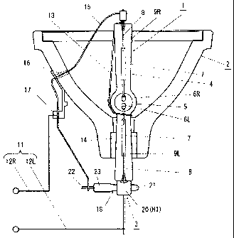
[Fig. 1] is an entire view showing an example of a light source
apparatus according to the present invention.
[Fig. 2] is a perspective view showing an example of a UV-enhancer
of a high pressure discharge lamp.
[Fig. 3] is a view showing an example of a holder forming an external
electrode of a discharge tube as the UV-enhancer.
[Fig. 4] is a view showing a modified example of a holder forming
the external electrode of the discharge tube.
[Fig. 5] is a view showing a modified example of a holder forming
the external electrode of the discharge tube.
[Fig. 6] is a view showing a modified example of the holder forming
the external electrode of the discharge tube.
[Fig. 7] is a view showing a prior art for enhancing the starting
performance of a high pressure discharge lamp.
[Fig. 8] is a view showing a prior art for enhancing the starting
performance of a high pressure discharge lamp.
[Fig. 9] is a view showing a prior art for enhancing the starting
performance of a high pressure discharge lamp.
[Fig. 10] is a view showing a prior art for enhancing the starting
performance of a high pressure discharge lamp.
[Fig. 11] is a view showing a prior art for enhancing the starting
performance of a high pressure discharge lamp.
[Description for References]
[0025]
1 ... high pressure discharge lamp
2 ... concave reflector
3 ... UV-enhancer
4 ... arc tube
- 14 -
CA 02734894 2011-03-29
... discharge bulb
6R ... electrode
6L ... electrode
7 ... metal foil
8 ... electrode lead
9R ... electrode sealed portion
9L ... electrode sealed portion
... end face of electrode seal portion
11 ... lighting circuit
14 ... bottom hole in a concave reflector
18 ... discharge tube
19 ... internal electrode
... external electrode
24 ... outer periphery of the discharge tube
Hl ... holder
H2 ... holder
H3 ... holder
... holder body
26 ... terminal (tab terminal)
27 ... window
H4 ... holder
31 ... holder body
32 ... terminal (sleeve terminal)
33 ... step
34 ... perforated hole
[Best Mode for Practicing the Invention]
[0026]
- 15 -
CA 02734894 2011-03-29
A best mode for practicing the light source apparatus according
to the present invention includes a high pressure discharge lamp in
which a pair of tungsten electrodes are disposed opposite each other
and mercury and a starting gas such as halogen and an argon gas are
sealed in a discharge bulb of an arc tube comprising a quartz glass
tube, a pair of electrode seal portions sealing each of the electrodes
are formed by airtightly sealing portions from the discharge bulb to
both ends of the arc tube and which is connected to a lighting circuit
by way of electrode leads comprising molybdenum wires protruding from
the endfacesofrespective electrode seal portions; a concave reflector
in which the lamp is attached by inserting one of the electrode seal
portions through the bottom hole opened in the bottom of the reflector;
and a UV-enhancer for radiating a UV-light for enhancing the starting
performance of the lamp upon starting the lighting thereof.
[0027]
The UV-enhancer comprises a discharge tube connected in parallel
with the lamp to a lighting circuit for applying a starting voltage
between the tungsten electrodes upon starting lighting of the lamp
and generating UV-light by the application of a starting voltage between
an external electrode and an internal electrode, the external electrode
of the discharge tube comprises a metal holder for holding the outer
periphery of the discharge tube so as to oppose the end face of one
of the electrode seal portions and securing the same to the electrode
lead protruding from the end face, and the holder comprises a holder
body for holding the outer periphery while exposing the surface of
the outer periphery opposite the end face of one of the electrode seal
portions and a terminal for securing and electrically connecting the
- 16 -
CA 02734894 2011-03-29
holder to the electrode lead.
[0028]
The main body of the discharge tube comprises a glass seal tube
made of quartz glass, in which a rare gas such as an argon gas is sealed,
an internal electrode comprising a metal foil such as a molybdenum
foil is contained and disposed inside the glass sealing tube, and a
lead welded to one end of the internal electrode protrudes from one
end of the glass sealing tube. The filler in the discharge tube is
not restricted onto the rare gas and it may also be a rare gas containing
mercury vapor.
[0029]
The holder body as the external electrode of the discharge tube
is formed of a metal sheet such as a stainless steel for spring bent
into a shape of gripping and holding the outer periphery of the discharge
tube. The metal sheet is bent into a shape of griping and holding
the outer periphery of the discharge tube at a position opposite the
end face of one of the electrode seal portions and formed with a window
for exposing the surface of the outer periphery opposing the end face,
or bent into a shape of gripping and holding the outer periphery so
as to expose the surface of the outer periphery of the discharge tube
opposite the end face at a the position opposing the end face of one
of the electrode seal portions.
[0030]
Further, the terminal for securing and electrically connecting
the holder to the electrode lead comprises a tub terminal formed from
17 -
CA 02734894 2011-03-29
a portion of the metal sheet forming the holder body, and the tab terminal
is bent so as to grip the electrode lead and spot welded to the electrode
lead.
[Example]
[0031]
Fig. 1 is an entire view showing an example of a light source
apparatus according to the present invention, Fig. 2 is a perspective
view showing a UV-enhancer of a high pressure discharge lamp used for
the light source apparatus, Figs. 3 (a) and (b) are a perspective view
and a side elevational view showing the constitution of a holder that
forms an external electrode of a discharge tube as the UV-enhancer
and the state of mounting the holder, respectively, Figs. 4(a) and
(b) and Figs. 5 (a) and (b) are a perspective view and a side elevational
view showing a modified example of the holder and the state of attaching
the holder respectively, and Figs. 6 (a) and (b) are a perspective view
and a partially cut away front elevatoinal view showing a modified
example and a state of mounting the holder, respectively.
[0032]
A light source apparatus shown in Fig. 1 includes a high pressure
discharge lamp 1, a concave reflector 2 for reflecting a light emitted
from the lamp 1, and a UV-enhancer 3 generating a UV-light for enhancing
the starting performance of the lamp 1. In the lamp i, a pair of tungsten
electrodes 6R and 6L are disposed and opposed at a short inter-electrode
distance of about 1 mm, and mercury and a starting gas such as a halogen,
for example, bromine and an argon gas are sealed in a discharge bulb
of an arc tube 4 comprising quartz glass, and portions from the
18 -
CA 02734894 2011-03-29
discharge bulb 5 to both ends of the arc tube 4 are airtightly sealed
to form a pair of electrode seal portions 9R and 9L that seal each
of the electrodes 6R and 6L, a metal foil 7 comprising a molybdenum
foil connected therewith, and electrode leads 8 comprising molybdenum
wires. Then, the electrode leads 8 and 8 protruding from the end faces
of respective electrode seal portions 9R and 9L are connected to
one side 12R and the other side 12L of the lighting circuit 11 for
supplying a lamp power, and a metal wire 13 as a trigger wire/antenna
wire for promoting arc discharge between the electrodes 6R and 6L is
wired such that one end thereof is connected with the electrode lead
8 protruding from the end face 10 of the electrode seal portion 9R
and the other end thereof is wound around in a loop form along the
outer periphery of the electrode seal portion 9L.
[0033]
The concave reflector 2 has, at its bottom, a bottom hole 14
apertured therein for allowing the electrode seal portion 9L on one
side of the high pressure discharge lamp 1 to pass therethrough and
securing the same with a cement or the like and, at its reflection
portion, a wiring hole 16 for allowing a lead wire 15 comprising a
nickel wire connected to an electrode lead 8 protruding from the
electrode seal portion 9R on the other side of the high pressure discharge
lamp 1 to pass therethrough. A wiring metal 17 is secured at the back
of the reflection portion for securing the lead wire 15 led out from
the wiring hole 16.
[0034]
The UV-enhancer 3 is connected in parallel with the lamp 1 to
- 19 -
CA 02734894 2011-03-29
the lighting circuit 11 for applying a starting voltage between the
electrodes 6R and 6L upon starting ignition of the high pressure
discharge lamp 1 and generates a UV-light by the application of the
starting voltage between the inner electrode 19 and the external
electrode 20 of the discharge tube 18.
[00351
The main body of the discharge tube 18 is formed of a glass sealing
tube 21 made of quartz glass and, in the inside of the glass sealing
tube 21, a rare gas such as an argon gas is filled, and an internal
electrode 19 comprising a metal foil such as a molybdenum foil having
a lead wire 22 welded at one end is contained and disposed. The glass
sealing tube 22 is sealed on one end by chipping off and pinch sealed
at the other end in which a welded portion between the internal electrode
19 and the lead wire 22 is sealed in the pinch sealed portion 23. Further,
the internal electrode 19 is connected by way of the lead wire 22
protruding from the pinch electrode seal portion 23 of the glass sealing
tube 21 to one side 12R (on the side of electrode 6R) of the light
circuit 11.
[00361
The external electrode 20 of the discharge tube 18 comprises a
metal holder H1 that holds the outer periphery 24 of the discharge
tube 18 so as to oppose the end face 10 of the electrode seal portion
9L of the lamp 1 inserted into the bottom hole 14 in the reflector
2 and secure the same to the electrode lead 8 protruding from the end
face 10. The holder H1 comprises a holder body 25 formed of a metal
sheet such as a stainless steel sheet (SUS 304-CSP) for spring of 0.2
- 20 -
CA 02734894 2011-03-29
mm thickness fabricated by bending into a shape of gripping and holding
the outer periphery 24 of the discharge tube 18, and a terminal 26
that secures and electrically connects the same to the electrode lead
8 protruding from the end face 10 of the electrode seal portion 9L.
[0037]
The metal sheet forming the body 25 of the holder H1 is bent into
a shape of gripping and holding the discharge tube 18 so as to cover
the outer periphery 24 of the tube at a position opposing to the end
face 10 of the electrode seal portion 9L. A window 27 for exposing
the surface of the periphery 24 opposing the end face 10 of the electrode
seal portion 9L is formed to the metal sheet. Further, a tab terminal
as a fixing terminal 26 is formed from a portion of the metal sheet
and the tub terminal is bent from the state indicated by a chain line
in Fig. 3 (a) so as to grip the electrode lead 8 as indicated by a solid
line and spot welded to the electrode lead 8, whereby the discharge
tube 18 is secured firmly to the electrode lead 8 comprising a rigid
molybdenum wire, and the external electrode 20 comprising the metal
holder Hl is connected electrically to the other side of the lighting
circuit 11 (on the side of the electrode 6L).
[0038]
Then, upon starting the lighting of the high pressure discharge
lamp 1, a starting voltage is applied from the lighting circuit 11
to a portion between the internal electrode 19 and the external electrode
20 of the discharge tube 18 to cause electric discharge in the rare
gas that excites the rare gas sealed in the glass seal tube 21
constituting the body of the discharge tube 18 thereby generating a
- 21 -
CA 02734894 2011-03-29
UV-light and the UV-light is radiated from the window 27 formed in
the body 25 of the holder H1 forming the external electrode 20, incident
to the end face 10 of the electrode seal portion 9L of the lamp 1,
transmitted and propagated inside the electrode seal portion 9L, and
is radiated into the discharge bulb 5, whereby the starting gas sealed
in the discharge bulb 5 is excited and tungsten forming the electrodes
6R and 6L emits initial electrons necessary for starting discharge
and promote starting of the high pressure lamp 1.
[0039]
Since the discharge tube 18 as the UV-enhancer 3 is inserted through
the bottom hole 14 in the reflector 2 and disposed at a position opposing
the end face 10 of the electrode seal portion 9L of the lamp protruding
to the outside of the reflector 2, it is not heated to a high temperature
during lighting of the lamp and, accordingly, can stably cause discharge
to generate a UV-light also during the hot state just after extinguishing
the lamp. Further, since the external electrode 20 of the discharge
tube 18 is formed of the holder H1 comprising the metal sheet bent
into the shape of gripping and holding the outer periphery 24 of the
discharge tube 18 where the internal electrode 19 is contained and
has a large electrode area, a UV-light can be generated in a necessary
and sufficient amount for enhancing the starting performance of the
lamp. Further, since the outer periphery 24 of the discharge tube
18 is opposed the end face 10 of the electrode seal portion 9L, the
UV-light generated in the discharge tube 18 can be incident efficiently
to the end face 10 of the electrode seal portion 9L.
[0040]
22 -
CA 02734894 2011-03-29
Further, since the discharge tube 18 has a simple constitution,
manufacturing cost thereof is not increased. Further, since the holder
H1 for holding the outer periphery 24 of the discharge tube 18 is secured
by welding to the electrode lead 8 of the lamp 1, there is no possibility
that it detaches fromthe electrode lead 8. Further, since the electrode
lead 8 is formed of a rigid molybdenum wire, there is no possibility
of causing such a disadvantage that the electrode lead 8 is
unintentionally bent and the outer periphery 24 of the discharge tube
18 held by the holder H1 does not oppose the end face 10 of the electrode
seal portion 9L.
[0041)
Further, in a holder H2 forming an external electrode 20 of a
discharge tube 18 shown in Fig. 4, its holder body 25 is formed of
a metal sheet comprising a stainless steel sheet for spring bent into
a shape of gripping and holding the outer periphery 24 so that the
surface of the outer periphery 24 of the discharge tube 18 opposing
the end face 10 is exposed at a position opposing the end face 10 of
the electrode seal portion 9L. A terminal 26 and a tab terminal for
securing and electrically connecting the holder H2 to the lead 8 are
formed from a portion of the metal sheet. That is, the metal sheet
forming the holder H2 is bent into a shape covering the peripheral
surface of the outer periphery 24 except for the surface of the outer
periphery 24 of the discharge tube 18 opposing the end face 10 of the
electrode seal portion 9L.
[0042]
With the constitution described above, since the UV-light emitted
- 23 -
CA 02734894 2011-03-29
from the outer periphery 24 of the discharge tube 18 to the end face
of the electrode seal portion 9L is incident directly to the end
face 10 thereof and, at the same time, the UV-light emitted from the
outer periphery 24 of the discharge tube 18 to the inner surface of
the body 25 of the holder H2 is also reflected at the inner surface
of the holder body 25 and incident to the end face 10 of the electrode
seal portion 9L, the amount of the UV-light radiated into the discharge
bulb 5 of the lamp 1 is increased to enhance the starting performance
of the lamp remarkably.
[0043]
Also in the holder H2 of Fig. 4, the terminal 26 comprising a
tab terminal is bent from the state indicated by a chain line so as
to grip the electrode lead 8 as shown by a solid line shown in Fig.
4(a) and welded to the electrode lead 8.
[0044]
Then, also in a holder H3 forming an external electrode 20 of
a discharge tube 18 shown in Fig. 5, a holder body 25 thereof is formed
of a metal sheet bent into a shape of gripping and holding an outer
periphery 24 of the discharge tube 18 in which the metal sheet has
a shape of gripping and holding one end of the outer periphery 24 of
the discharge tube 18 so as to dispose the other end of the outer periphery
24 thereof at a position opposing the end face 10 of an electrode seal
portion 9L. Further, also in the holder H3, a tab terminal as a terminal
26 is formed from a portion of the metal sheet forming the main body
25 thereof, and the tab terminal 26 is bent so as to grip the electrode
lead 8 as indicated by a solid line in Fig. 5 (a) from a state indicated
- 24 -
CA 02734894 2011-03-29
by a chain line and spot welded to the electrode lead 8. Further,
although not illustrated in the drawing, a heat resistant adhesive
is coated between the outer periphery 24 of the discharge tube 18 and
the main body 25 of the holder H3 for holding the outer periphery,
by which the discharge tube 18 is secured to the holder H3.
[0045]
Then, also an external electrode 20 of a discharge tube 18 shown
in Fig. 6 is formed as a holder H4 that holds the outer periphery 24
of a discharge tube 18 so as to oppose the end face 10 of an electrode
seal portion 9L and secures the same to an electrode lead 8 protruding
from the end face 10 thereof. The holder H4 is formed as a stepped
metal tube in which a large diameter portion as a holder body 31 that
holds the outer periphery 24 of the discharge tube 18 in a state of
exposing the surface of the outer periphery 24 of the discharge tube
18 opposing the end face 10 of an electrode seal portion 9L, and a
small diameter portion as a terminal 32 that secures and electrically
connects the holder to the electrode lead 8 are contiguous with each
other by way of a stepped portion 33.
[00461
In the stepped metal tube forming the holder H4, a pair of through
holes 34, 34 are perforated to the large diameter portion as the holder
body 31 for allowing the discharge tube 18 to be inserted therethrough
in the diametrical direction and holding the both ends of the outer
periphery 24 of the discharge tube 18, and the small diameter portion
as the terminal 32 forms a sleeve terminal for allowing an electrode
lead 8 to be inserted therethrough and securing the same to the electrode
- 25 -
CA 02734894 2011-03-29
lead 8 by caulking and welding.
[0047]
In the holder H4, as shown in Fig. 6 (a) , the electrode lead 8 protruding
from the end face 10 of the electrode seal portion 9L is at first inserted
through the holder body (large diameter portion) 31 and the sleeve
terminal (small diameter portion) 32 and then, as shown in Fig. 6 (b) ,
the sleeve terminal (small diameter portion) 32 is engaged by caulking
and welding to the electrode lead 8 and secured in a state of capping
the holder body (large diameter portion) 31 over the end of the electrode
seal portion 9L. Further, the discharge tube 18 inserted through the
through holes 34 and 34 of the holder body 31 and held is secured at
the portion protruding externally from the through holes 33, 33 of
the holder body 31 to the outer surface of the holder body 31 by heat
resistant adhesives.
[Industrial Applicability]
[0048]
The present invention contributes to the improvement of the
starting performance of a high pressure discharge lamp used as a light
source apparatus for liquid crystal projectors, DLP projectors, etc.
26 -