Note: Descriptions are shown in the official language in which they were submitted.
CA 02734907 2011-03-23
Method for mounting photovoltaic modules and a photovoltaic array
[0001] The invention relates to a method for mounting photovoltaic modules and
to a
photovoltaic array of the generic type described in European patent
application EP
2 109 153 A2.
[0002] European patent application EP 2 109 153 A2 discloses a solar element
for a
photovoltaic array that has several attachment elements on its back that are
attached by
means of an adhesive bond to the base body of the solar element. The
photovoltaic
module that has been prefabricated in this manner is subsequently mounted onto
a
stationary substructure that is situated, for example, on a roof and that has
a rail system
with several holding rails. A drawback of such a photovoltaic array is that
the modules
can be damaged or break, especially in the case of photovoltaic modules with a
large
surface area and in the case of exposure to mechanical load due to the
component stresses
that occur.
[0003] Before this backdrop, the invention is based on the objective of
putting
forward a way to mount photovoltaic modules such that a high mechanical load-
bearing
capacity of the modules can be achieved with minimal effort in terms of
production
technology and with low manufacturing and assembly costs.
[0004] According to the invention, this objective is achieved by a method for
mounting photovoltaic modules having at least one photovoltaic module that can
be
secured to a stationary substructure by means of attachment elements in that,
first of all, a
calculation of the structural load of the photovoltaic module is carried out
under the
mechanical load that can be expected during actual operation later on, in
order to
determine optimized attachment locations for the attachment elements, in that
the
attachment elements are then arranged at the attachment points that have been
optimized
as a function of the load, whereby the attachment elements extend partially
over a partial
-1-
CA 02734907 2011-03-23
section of the photovoltaic modules, and subsequently the photovoltaic modules
are
attached to the substructure by means of the attachment elements.
[0005] In comparison to the state of the art, it was recognized according to
the
invention that the mechanical load-bearing capacity of the attachment of
photovoltaic
modules can be improved by calculating the structural load of the photovoltaic
module
under mechanical load and by optimizing the arrangement of the attachment
elements to
the attachment points that have been determined as a function of the load. The
virtually
punctual attachment of the photovoltaic modules at defined attachment points
allows an
improved distribution of the load-dependent deformation of the modules. The
number
and dimensions of the attachment elements are preferably determined as a
function of the
module size and module shape. In this manner, it is possible to securely affix
modules
that have particularly large surface areas, especially frameless modules, and
that are
configured as glass-glass photovoltaic modules having a surface area of more
than 1 m2.
[0006] According to the invention, an overall high load-bearing capacity of
the
photovoltaic array is achieved with minimal material resources, so that the
effort in terms
of production technology is minimized and costs during the production,
transport and
assembly are reduced.
[00071 A load-dependent, punctual or sectional linear attachment of the
photovoltaic
modules is provided according to a proposal of the invention. The attachment
points are
preferably determined on the basis of computer-implemented strength models.
The
attachment that has been optimized according to the invention allows a better
distribution
of the load-dependent deformation of frameless photovoltaic modules.
[0008] It has proven to be especially advantageous for the calculation of the
structural
load to be carried out by means of computer-implemented simulation, preferably
by a
finite element analysis (FEA) method and/or y a stress analysis. For example,
the
-2-
CA 02734907 2011-03-23
attachment points of the attachment elements are determined by means of
computer-
implemented strength models.
[0009] Damping elements, especially made of an elastomer, can be provided in
the
area of the attachment points in order to further improve the load application
and in order
to minimize stresses in the glass, especially in the edge area of the modules
when they are
under load.
[0010] The substructure can be configured as a rail system with several
holding rails
extending essentially parallel, in order to affix the photovoltaic modules.
Such rail
systems can be arranged, for example, on the roof and/or on a wall of a
building or the
like.
[0011] The photovoltaic modules preferably span several of the holding rails,
whereby each holding rail has at least two attachment elements arranged at a
distance
from each other.
[0012] In a first concrete embodiment, each photovoltaic modules spans three
holding
rails, whereby each holding rail has three attachment elements arranged at a
distance
from each other.
[0013] In such a variant, the attachment elements are arranged essentially in
a circle,
whereby each attachment element is positioned in an angular range of 0 , 45 ,
90 , 135 ,
180 , 225 , 270 and 315 , and whereby the 0 or 180 axis of the angular
range extends
approximately at an angle of 90 with respect to the longitudinal axis of the
holding rails.
This results in a homogeneous stress distribution in the photovoltaic module
and an
optimized force application into the substructure.
[0014] In this embodiment, it has proven to be very advantageous in terms of
structural mechanics for the longitudinal axes of the attachment elements that
are
-3-
CA 02734907 2011-03-23
positioned in the angular range of 90 and in the angular range of 270 to
extend
approximately parallel, and for the longitudinal axes of the attachment
elements that are
positioned in the angular range of 0 , 45 , 135 , 180 , 225 and 315 to
extend
approximately perpendicular to the appertaining longitudinal axis of the
holding rail.
Moreover, it is preferable for at least one attachment element to be
positioned in the area
of the center of the circle. All in all, this allows a further optimized force
flow.
[0015] According to an alternative embodiment of the invention, each
photovoltaic
modules spans four holding rails, whereby each holding rail has at least two
attachment
elements arranged at a distance from each other whose longitudinal axes
preferably
extend at an angle in the range of approximately 90 with respect to the
longitudinal axis
of the holding rails. In a preferred embodiment, all of the attachment
elements are
attached to the photovoltaic module in such a way that they each extend at an
angle in the
range of about 90 with respect to the longitudinal axis of the holding rail.
[0016] However, it can also be advantageous for the attachment elements to be
simply arranged in parallel and orthogonally with respect to the holding
rails, whereby
the attachment elements can also extend over several holding rails.
[0017] According to the invention, it is especially advantageous for the
attachment
elements to be attached to the back of the photovoltaic modules by means of an
adhesive
bond. In this manner, the attachment elements can be mounted easily and
quickly onto
the photovoltaic modules. Moreover, in terms of production technology, the
attachment
elements can be affixed easily, for example, automatically, onto the bottom of
the
photovoltaic modules during their manufacture. Drilled holes and other
openings in the
modules are not necessary in order to attach the attachment elements, which
translates
into a high strength of the modules.
[0018] The attachment elements are especially advantageously attached to the
photovoltaic modules by means of silicon or an adhesive containing a silicon
compound.
-4-
CA 02734907 2011-03-23
Such adhesives have an elastic behavior with high strength so that no
mechanical stresses
between the substructure and the photovoltaic modules, or at least fewer, are
transmitted,
for example, due to different coefficient of thermal expansion.
[0019] As an alternative, the attachment elements can be attached to the
photovoltaic
modules by means of double-stick adhesive tape. In addition to being easy to
apply, this
also has the advantage that no curing times for the adhesive bond have to be
taken into
account.
[0020] Preferably, at least one of the attachment elements is arranged in an
edge area
of the photovoltaic module so that the modules are held especially securely as
a result of
the leverage ratios.
[0021] The photovoltaic module according to the invention has at least one
photovoltaic module that can be secured onto a stationary substructure by
means of
attachment elements. According to the invention, the photovoltaic module has
several
partially arranged attachment elements for attaching the module to the
substructure,
which extend only over a partial section of the photovoltaic modules, whereby
the
attachment points of the attachment elements were determined as a function of
the load.
[0022] In a preferred embodiment of the photovoltaic array, the attachment
elements
have an approximately omega-shaped profile cross section, whereby a middle
section of
the attachment elements is joined to the substructure and free profile legs
are attached to
the photovoltaic module. Any other profile cross section with which the
photovoltaic
module can be joined to the substructure is likewise conceivable.
[0023] In order to further reduce the mechanical stresses between the
attachment
elements and the substructure, for example, due to different coefficients of
thermal
expansion on the part of the modules and of the substructure, damping elements
are
-5-
CA 02734907 2011-03-23
preferably arranged between the attachment elements and the substructure. In
particular,
an elastomer can be provided as the damping element.
[0024] Other advantageous refinements of the invention are an integral part of
the
further subordinate claims.
[0025] The invention will be explained in greater detail below with reference
to
embodiments. The accompanying drawings show the following:
Figure 1 a top view of a mounted photovoltaic array in a first embodiment
according to the invention,
Figure 2 a side view of the photovoltaic array of Figure 1,
Figure 3 a top view of a mounted photovoltaic array in a second embodiment
according to the invention, and
Figure 4 a side view of the photovoltaic array of Figure 3.
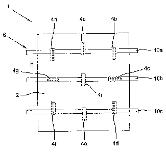
[0026] Figure 1 shows a photovoltaic array 1 according to the invention with a
flat
arrangement of the photovoltaic module 2 that is attached by means of several
attachment
elements 4a-4i provided on a stationary substructure 6. The photovoltaic
module 2,
shown by way of an example, is configured as a glass-glass laminate and, in
the
embodiment shown, is attached by means of the substructure 6 onto a building
roof 8.
[00271 According to the invention, before the photovoltaic module 2 is
mounted, a
calculation of the structural load of the module under the assumed mechanical
load later
on is carried out in order to determine optimized attachment points for the
attachment
elements 4a-4i. The calculation of the structural load was carried out by
means of a
computer-implemented finite element analysis. In this context, a determination
of the
attachment points on the basis of computer-implemented strength models has
proven to
-6-
CA 02734907 2011-03-23
be especially advantageous. The attachment elements 4a-4i were subsequently
arranged
at the attachment points that had been optimized as a function of the load,
whereby the
attachment elements 4a-4i extend partially over a partial section of the
photovoltaic
modules 2. The attachment elements 4a-4i each preferably extend over a length
encompassing approximately 10% to 20% of the length of the module.
[0028] Subsequently, the photovoltaic modules 2 were attached to the
substructure 6
by means of the attachment elements 4a-4i. Thanks to the calculated
arrangement of the
attachment elements 4a-4i to the attachment points that had been optimized as
a function
of the load, a high mechanical strength of the attachment is ensured, even in
case of a
high mechanical load. As a result, it is possible to securely affix modules
that have
particularly large surface areas, especially frameless modules, and that are
configured as
glass-glass photovoltaic modules having a surface area of more than I m2. The
depicted
module 2, for example, has a surface area of approximately 5.72 m2.
[0029] The substructure 6 is configured as a rail system with several holding
rails
I0a-IOc extending parallel to each other in order to affix the photovoltaic
modules 2. In
the embodiment shown, the photovoltaic modules 2 each span three holding rails
1Oa-IOc, whereby each holding rail I0a-10 has three attachment elements
arranged at a
distance from each other. The attachment elements 4a-4h are arranged
essentially in a
circle, whereby in each case, an attachment element 4a-4h is positioned in an
angular
range of 0 , 45 , 90 , 135 , 180 , 225 , 270 and 315 , and whereby the 0 or
180 axis
of the angular range extends approximately at an angle of 90 with respect to
the
longitudinal axis of the holding rails. Here, it has proven to be very
advantageous in
terms of structural mechanics for the longitudinal axes of the attachment
elements 4c, 4g
that are positioned in the angular range of 90 and in the angular range of
270 to extend
approximately parallel, and for the longitudinal axes of the attachment
elements 4a, 4b,
4d, 4e, 4f, 4h that are positioned in the angular range of 0 , 45 , 135 , 180
, 225 and
315 to extend approximately perpendicular to the appertaining longitudinal
axis of the
holding rails and to only be joined to the holding rail 10a, l Oc in an edge
area. The
-7-
CA 02734907 2011-03-23
attachment element 4i is arranged in the area of the center of the circle in
the middle of
the middle holding rail l Ob.
[0030] As can be seen in Figure 2, which shows a side view of the photovoltaic
array
1 from Figure 1, the attachment elements 4a-4i have an approximately omega-
shaped
profile cross section, whereby a middle section 12 of the attachment elements
4a-4i is
joined to the substructure 6, and free profile legs 14a, 14b are attached to
the photovoltaic
module 2. An elastomer damping element 16 with an approximately rectangular
cross
section is arranged between each of the attachment elements 4a-4i and the
substructure 6.
Here, the joining surface of the damping element 16 corresponds to the surface
of the
middle section 12 of the attachment elements 4a-4i. The attachment elements 4a-
4i are
attached to the back of the photovoltaic modules 2 by means of a silicon-based
adhesive,
so that no mechanical stresses, or at least fewer, occur. Drilled holes and
other openings
are not necessary in order to attach the modules 2, so that all in all, a high
strength is
achieved. It should be explicitly pointed out that the omega-shaped profile
cross section
can have any other shape with outer surfaces that are configured in parallel
opposite from
each other.
[0031] Figure 3 shows a photovoltaic array 100 according to a second
embodiment
according to the invention that differs from the above-mentioned embodiment
essentially
by a simplified arrangement of the attachment elements. According to Figure 3,
the
photovoltaic modules 102 here each span four holding rails 104a-104d, whereby
each
holding rail 104a-I04d has two attachment elements 106a-106h arranged at a
distance
from each other in edge areas of the modules 102. The attachment elements 106a-
106d
and the attachment elements 106e-106h are each arranged in a row with a shared
longitudinal axis. The longitudinal axes of the attachment elements 106a-106h
extend at
an angle of approximately 90 with respect to the longitudinal axis of the
holding rails.
104a-104d. The photovoltaic module 102 that is shown by way of an example and
that is
secured in a manner optimized according to the invention has a surface area of
approximately 2.86 m2.
-8-
CA 02734907 2011-03-23
[0032] As can be seen in Figure 4, which shows a side view of the photovoltaic
array
100 of Figure 3, the attachment elements 106a-106h are configured as already
explained
for Figure 2, so that reference is hereby made to this part of the
description.
[0033] According to the invention, all in all, a high load-bearing capacity of
the
photovoltaic array 1, 100 is achieved with minimal material resources, so that
the effort
in terms of production technology is minimized and costs are reduced during
the
production, transport and assembly.
[0034] A method is disclosed for mounting photovoltaic modules 2, 102 having
at
least one photovoltaic module 2, 102 that can be secured to a stationary
substructure 6 by
means of attachment elements 4, 106, comprising the steps:
a) calculation of the structural load of the photovoltaic module 2, 102 under
a
mechanical load that can be expected, in order to determine optimized
attachment
points for the attachment elements 4, 106,
b) arrangement of the attachment elements 4, 106 at the attachment points that
have
been optimized as a function of the load, whereby the attachment elements 4,
106
extend partially over a partial section of the photovoltaic modules 2, 102,
and
c) attachment of the photovoltaic modules 2, 102 to the substructure 6 by
means of
the attachment elements.
[0035] Moreover, a photovoltaic array is disclosed with several partially
arranged
attachment elements 4, 106, whereby the attachment points of the attachment
elements 4,
106 were determined as a function of the load.
-9-
CA 02734907 2011-03-23
List of reference numerals
1 photovoltaic array
2 photovoltaic module
4a-4i attachment element
6 substructure
8 building roof
lOa-10c holding rail
12 middle section
14a-14b profile leg
16 damping element
100 photovoltaic array
102 photovoltaic module
104a-104d holding rail
106a-106h attachment element
-10-