Note: Descriptions are shown in the official language in which they were submitted.
CA 02735219 2016-01-20
Fluid Recirculation Debris Handling System
Background
1[] Endometrial ablation is a procedure conducted to reduce or eliminate
excessive uterine bleeding by ablating the innermost lining of the uterus,
known as
the endometrium. One method of ablating the endometrium is by using the
HydroThermAblator System (HTA) which circulates heated fluid in the uterus. A
sheath is inserted into the uterus via the cervix to introduce and circulate
the
heated fluid and to maintain a target ablation temperature through the uterus.
An
ablation sheath generally includes an inlet lumen via which the heated fluid
is
introduced into the uterus and a return lumen via which the fluid may be
returned,
heated and circulated back into the body to maintain the target ablation
temperature.
Summary of the Invention
20 The present invention is directed to a device for circulating fluid to a
target
site within a living body, comprising a longitudinal member including an inlet
lumen
supplying fluid to the target site and a return lumen withdrawing fluid from
the
target
1
8007877.1
CA 02735219 2011-02-24
WO 2010/036434 PCT/US2009/049221
site, the return lumen surrounding the inlet lumen and a screen coupled to a
distal end
of the longitudinal member, the screen including a plurality of openings
extending
therethrough from a radially inner surface forming a radially outer wall of a
distal portion
of the return lumen to an outer surface thereof.
Brief Description of the Drawings
30 Fig. 1 shows a perspective view of a device according to a first exemplary
embodiment of the present invention;
Fig. 2 shows a longitudinal cross-sectional view of the device of Fig. 1;
Fig. 3 shows a lateral cross-sectional view of the device of Fig. 1;
Fig. 4 shows a perspective view of a distal end of the device of Fig. 1;
Fig. 5 shows a longitudinal cross-sectional view of a device according to a
second exemplary embodiment of the present invention;
Fig. 6 shows a perspective view of a distal end of the device shown in Fig. 5;
Fig. 7 shows a perspective view of a device according to a third exemplary
embodiment of the present invention; and
Fig. 8 shows a perspective view of a device according to a fourth exemplary
embodiment of the present invention.
Detailed Description
40 The present invention, which may be further understood with reference to
the
following description and the appended drawings, wherein like elements are
referred to
2
CA 02735219 2011-02-24
WO 2010/036434 PCT/US2009/049221
with the same reference numerals, relates to devices for treating an
endometrial lining
of a uterus. In particular, the present invention relates to devices for
circulating heated
fluid through hollow organs such as the uterus to treat tissue therein (e.g.,
the
endometrium). As the endometrial lining is ablated, debris is often generated
in the
uterus. Exemplary embodiments of the present invention provide a device for
circulating fluid, including a distal tip that prevents the debris from
returning into and
occluding the device, thereby preventing any impedance of the circulatory flow
of the
fluid. As would be understood by those skilled in the art, although this
invention is
described in conjunction with the ablation of the endometrium, the invention
may be
used in conjunction with the treatment of the tissue of any hollow organ.
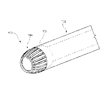
50 As shown in Figs. 1 -4, a device 100, according to an exemplary embodiment
of
the invention comprises a longitudinal member 102 and a screen 104 located at
a distal
end 106 thereof. The device 100 may be sized and shaped to be inserted into an
internal space of a living body, in particular, to be inserted into a uterus
via a cervix. In
a preferred embodiment, an outer diameter of the device 100 may range from
approximately 7.0 mm to 7.7 mm to ensure ease of insertion of the device 100
into the
uterus via the cervix. As shown in Figs. 2 -3, the longitudinal member 102
comprises a
first sleeve 108 housed within a second sleeve 110 which is housed within a
third
sleeve 112. The sleeves 108, 110, 112 in this example are co-axial. An inlet
lumen 114
within the first sleeve 108 extends from a proximal end (not shown)
connectable to a
supply of ablation fluid so that, when in a desired position within the body,
fluid
introduced thereinto flows into the uterus via a distal opening 122. The first
sleeve 108
may be formed of a metal such as, for example, stainless steel. It will be
understood by
those of skill in the art that the metal will provide mechanical stability and
stiffness of the
longitudinal member 102, while providing an optimal cross-sectional fluid flow
area. A
hysteroscope 116 may also be introduced into the body via the lumen 114 with
fluid
continuing to flow in an annular space between the hysteroscope and the wall
of the
lumen 114 as shown by the arrows in Fig. 2. The metal material of the first
sleeve 108
3
CA 02735219 2011-02-24
WO 2010/036434 PCT/US2009/049221
guides a sometimes sharp tip of the hysteroscope 116 without catching on or
damaging
the material of the first sleeve 108.
60 A return lumen 118 formed in an annular space between an outer surface of
the
first sleeve 108 and an inner surface of the second sleeve 110 opens to the
outside of
the device 100 via a plurality of slots 130 extending through a screen 104
which is
mounted over the distal end 106. The screen includes an opening 126 through
which
fluid from the distal opening 122 of the lumen 114 passes into the uterus.
Negative
pressure may be applied to the return lumen 118 to draw fluid from the region
surrounding the distal end 106 through the screen 104 into the return lumen
118 for
withdrawal from the body. In an alternative embodiment, a positive pressure
may be
applied through the lumen 114 elevating the pressure within the uterus and
forcing fluid
out of the uterus through the screen 104 and into the distal end 124 of the
return lumen
118. After removal from the body, the fluid from the return lumen 118 may be
filtered,
reheated and returned to the uterus via the lumen 114 or may be withdrawn from
circulation and replaced by fresh fluid as desired. The screen 104 facilitates
the return
of this fluid by providing an initial filtering of the fluid to reduce
particles suspended
therein. In one embodiment, an area of the return lumen 118 may be
approximately
0.009 sq. inches.
70 An insulative gap 120 is formed in an annular space between an inner
surface of
the third sleeve 112 and an outer surface of the second sleeve 110. The
insulative gap
120 may be filled with air to minimize heat transfer from the fluids flowing
through the
inlet lumen 114 and the fluid return lumen 118 to non-targeted tissue adjacent
to the
device 100 to prevent burns and/or other damage to this surrounding tissue. It
will be
understood by those of skill in the art that the second sleeve 110, which
forms part of
insulative gap 120, may be formed of a plastic or other thermally insulative
material. As
would be understood by those skilled in the art, one or more additional layers
of
insulation may be provided if desired.
4
CA 02735219 2011-02-24
WO 2010/036434 PCT/US2009/049221
80 As shown in Fig. 2, the first sleeve 108 extends distally past the second
sleeve 110
such that an opening 122 of the inlet lumen 114 is distally beyond a distal
opening 124
of the return lumen 118. Thus, fluid entering the return lumen 118 will do so
via the
screen 104 at locations proximal of the distal opening 122 of the lumen 114.
it will be
understood by those of skill in the art that a staggered flow pattern is
established such
that all of the fluid flow through the inlet lumen 114 is forced into the
uterus and back to
the return lumen 118. This staggered flow pattern creates greater turbulence
within the
uterus and allows for better heat distribution through the uterus. The screen
104 is
coupled to the distal end 106 of the device such that a distal end 126 of the
screen 104
is substantially aligned with the opening 122 of the inlet lumen 114 formed by
the first
sleeve 108. The screen 104 may be coupled to the longitudinal member 102 by
any
number of coupling means. For example, the screen 104 may include a male
mating
component 132 that is receivable within the insulative gap 120 between the
second and
third sleeves 110, 112, which acts as a female mating component. The male
mating
component 132 and the female mating component of the insulation gap 120 may be
locked together.
90 As shown in Fig. 4, the screen 104 includes an open distal end 126
substantially
similar in diameter to a diameter of the inlet lumen 114. The screen 104 is
substantially
dome-shaped with an outer surface of the screen 104 curved and a proximal end
128 of
the screen 104 shaped to be received within the insulative gap 120 between the
inner
surface of the third sleeve 112 and the outer surface of the second sleeve
110. During
endometrial ablation procedures, the cervix is generally dilated to
approximately 8mm to
reduce the force required to insert an HTA device therethrough. As would be
understood by those skilled in the art, the dome shape of the screen 104 and
the
tapered distal end 126 reduce the force required to insert the device 100 into
the body
possibly allowing the insertion of the device 100 with a lesser amount of
dilation
reducing trauma to the surrounding tissue. Additionally, the dome shape of the
screen
CA 02735219 2011-02-24
WO 2010/036434 PCT/US2009/049221
104 may increase the structural stability of the screen 104, as loads during
insertion are
distributed substantially evenly around a circumference of an outer surface of
the
screen 104. It will be understood by those of skill in the art, however, that
although the
screen 104 is shown to be dome-shaped, the screen 104 may take a variety of
shapes.
These shapes will generally include a taper with the distal opening 126 being
smaller
than the proximal end 128 to facilitate insertion. For example, the screen 104
may be
hemispherically shaped to provide an optimal level of strength. In an
alternative
embodiment, the screen 104 may have a truncated conical shape to facilitate
insertion
into the cervical cavity. In yet another embodiment, the screen 104 may be
have a
substantially parabolic dome shape such that the screen 104 may retain a level
of
strength, while still facilitating insertion into the cervical cavity.
100 The distal end 126 of the screen 104 extends from a distal end 138 of the
first
sleeve 108 proximally past a distal end 140 of the second sleeve 110 such that
return
fluid must first pass through the screen 104 to access the opening 124 of the
return
lumen 118. The screen 104 includes a plurality of slots 130 distributed around
at least a
portion of a circumference thereof with each slot extending along at least a
portion of
the length of the screen 104 (i.e., parallel to a longitudinal axis of the
device 100) and
passing from an opening in an outer surface 134 through an inner surface 136
of the
screen 1 04. A width of each slot 130 may be made smaller than a width of the
return
lumen 118 to ensure that any debris that is able to pass through the screen
104, is too
small to occlude the return lumen 118. As the screen 104 extends distally past
the
distal end of the second sleeve 110, the slots 130 increase the total area
available for
fluid to enter the return lumen 118 without substantially affecting the
pressure in the
return lumen 118. In a preferred embodiment, the aggregate area of the slots
130 is
approximately five times the cross-sectional area of the return lumen 118. For
example,
if the cross-sectional area of the return lumen 118 is approximately 0.009 sq.
inches,
the aggregate area of the slots 130 may be approximately 0.05 sq. inches. This
allows
the pressure and the flow characteristics of the return lumen 118 to remain
acceptable
6
CA 02735219 2011-02-24
WO 2010/036434
PCT/US2009/049221
even if 80% or more of the screen 104 were occluded with debris. Additionally
as will
be understood by those of skill in the art, the distribution of the total area
of the slots
130 over the surface of the screen 104 reduces the velocity and pressure with
which
fluid first contacts the longitudinal member 102 reducing the likelihood of
large debris
becoming embedded within the slots 130.
110 As shown in Figs. 5 - 6, a device 200 according to another embodiment of
the
present invention comprises a longitudinal member 202 and a screen 204 coupled
to a
distal end 206 thereof. Similarly to the device 100, the longitudinal member
202
includes a first sleeve 208, a second sleeve 210, and a third sleeve 212, each
of which
share a longitudinal axis. In the device 200, the first sleeve 208 extends
slightly distally
of the second and third sleeves, 210 and 212, respectively, with an outer wall
of a distal
portion of the return lumen 218 being formed by an inner surface of a mating
component 232 of the screen 204. The mating component 232 is received within
an
annular space 220 between the outer surface of the second sleeve 210 and an
inner
surface of the third sleeve 212 and extends distally to a screen portion ,234
of the
screen 204. As described above, this annular space 220 serves as an insulation
gap
minimizing heat transfer between the heated fluids in the longitudinal member
202 and
surrounding tissue. When mated to the longitudinal member 202, the mating
component 232 ends at a point substantially aligned with the distal end 238 of
the first
sleeve 208 so that the return lumen 218 terminates at a point aligned with the
distal
opening 222 of the working channel 214. As shown in Fig. 5, the working
channel 214
is sized so that, when a hysteroscope 216 is inserted therein, an annular
space
surrounding the hysteroscope 216 functions as an inlet lumen 217 for the
device 200.
120 The screen 204 may be substantially similar to the screen 104. A distal
opening
226 of the screen 204, however, may be smaller than the distal opening 126 and
the
mating component 232 of the screen 204 may mate with the longitudinal member
202
such that a proximal end 228 of the screen portion 234 substantially aligns
with the
7
CA 02735219 2011-02-24
WO 2010/036434 PCT/US2009/049221
distal end 238 of the first sleeve 208. The screen 204 covers the entire
distal end 206
of the longitudinal member 202 to prevent debris from entering the debris
lumen 218. It
will be understood by those of skill lin the art, that the aggregate area of
the slots 230 is
preferably substantially greater than an aggregate cross-sectional area of the
inlet and
return lumens 217, 218, respectively, so that the flow characteristics of
these lumens
may remain unchanged even when a significant portion of the area of the slots
230 is
blocked by debris removed from the return fluid.
130 As shown in Fig. 6, the screen 204 includes a plurality of slots 230
substantially
similar to the slots 130 of screen 104. The slots 230 extend around at least a
portion of
a circumference of the screen 230, and each slot 230 may extend along at least
a
portion of a length of the screen 204. A width of each of the slots 230 is
preferably
smaller than a width of the opening 224 of the return lumen 218 so that any
debris that
passes through the screen 204 via the slots 230 will be too small to occlude
the return
lumen 218.
140 As shown in Fig. 7, a device 300, according to an alternate embodiment of
the
present invention, comprises a longitudinal member 302 and a screen 304
coupled to a
distal end 306 thereof. The longitudinal member 304 may be substantially
similar to
either of the longitudinal members 102 and 202, respectively, described above
in regard
to devices 100, 200. The screen 304 may also be substantially similar to the
screens
104 and 204, including an open distal end 326 that is smaller in diameter than
a
proximal end 328 of the screen 304. It will be understood by those of skill in
the art that
although the screen 304 is shown to be substantially conically shaped, the
screen 304
may take a variety of shapes so long as the distal opening 326 is smaller than
the
proximal end 328. For example, the screen 304 may be dome-shaped,
150 The screen 304 further includes a plurality of holes 330 distributed
around at least
a portion of a circumference and a portion of a length of the screen 404, Each
of the
holes 330 extends from an outer surface 334 to an inner surface 336 such that
return
8
CA 02735219 2011-02-24
WO 2010/036434 PCT/US2009/049221
fluid must pass through the holes 330 to access a return lumen (not shown).
Each of the
holes 330 may be smaller in size than an opening of the return lumen to ensure
that any
debris that is able to pass through the holes 330 are too small to occlude the
return
lumen. It will be understood by those of skill lin the art, that the aggregate
area of the
holes 330 is preferably substantially greater than an aggregate cross-
sectional area of
the inlet and return lumens of the longitudinal member 302 so that the flow
characteristics of these lumens may remain unchanged even when a significant
portion
of the area of the holes 330 is blocked by debris removed from the return
fluid.
160 As shown in Fig. 8, a device 400, according to an alternate embodiment of
the
present invention, comprises a longitudinal member 402 and a screen 404
attached to a
distal end 406 thereof. The longitudinal member 402 may be substantially
similar to
either of the longitudinal members 102 and 202, respectively, described above
in regard
to devices 100, 200. The screen 404 may also be substantially similar to the
screens
104, 204 and 304, including an open distal end 426 that is smaller in diameter
than a
proximal end 428 of the screen 404. It will be understood by those of skill in
the art that
although the screen 404 is shown to be substantially conically shaped, the
screen 404
may take a variety of shapes. As indicated above, tapered shapes may be
desired to
facilitate insertion. For example, the screen 404 may be dome-shaped, conic,
etc.
17n The screen 404 further includes a plurality of slots 430 distributed along
at least a
portion of a length of the screen 404, each of the slots 430 extending around
at least a
portion of a circumference of the screen 404. Each of the slots 430 extends
from an
outer surface 434 to an inner surface 436 such that return fluid must pass
through the
slots 430 to access a return lumen (not shown). Each of the slots 430 may be
smaller in
width than opening of the return lumen to ensure that any debris that is able
to pass
through the slots 430 is too small to occlude the return lumen. It will be
understood by
those of skill in the art, that the aggregate area of the holes 430 is
preferably
substantially greater than an aggregate cross-sectional area of the inlet
and/or return
9
CA 02735219 2011-02-24
WO 2010/036434
PCT/US2009/049221
lumens of the longitudinal member 402 so that the flow characteristics of
these lumens
may remain unchanged even when a significant portion of the area of the slots
430 is
blocked by debris removed from the return fluid.
180 It
will be understood by those of skill in the art that various modifications and
variations can be made in the structure and the methodology of the present
invention
without departing from the sprit or the scope of the invention. Thus, it is
intended that
the present invention cover the modifications and the variations of this
invention
provided that they come within the scope of the appended claims and their
equivalents.
I0