Language selection

Search

Patent 2735448 Summary

Third-party information liability

Some of the information on this Web page has been provided by external sources. The Government of Canada is not responsible for the accuracy, reliability or currency of the information supplied by external sources. Users wishing to rely upon this information should consult directly with the source of the information. Content provided by external sources is not subject to official languages, privacy and accessibility requirements.

Claims and Abstract availability

Any discrepancies in the text and image of the Claims and Abstract are due to differing posting times. Text of the Claims and Abstract are posted:

  • At the time the application is open to public inspection;
  • At the time of issue of the patent (grant).
(12) Patent: (11) CA 2735448
(54) English Title: CURVED SHOWER ROD MOUNTING SYSTEM
(54) French Title: SYSTEME DE MONTAGE DE TIGE DE DOUCHE COURBE
Status: Expired and beyond the Period of Reversal
Bibliographic Data
(51) International Patent Classification (IPC):
  • A47H 01/142 (2006.01)
  • A47K 03/38 (2006.01)
(72) Inventors :
  • MANGA, IOSIF OVIDIU (United States of America)
  • WELKER, KEVIN (United States of America)
(73) Owners :
  • BRASSTECH INC.
(71) Applicants :
  • BRASSTECH INC. (United States of America)
(74) Agent: HEENAN BLAIKIE LLP
(74) Associate agent:
(45) Issued: 2013-09-10
(22) Filed Date: 2011-03-28
(41) Open to Public Inspection: 2011-10-13
Examination requested: 2011-03-28
Availability of licence: N/A
Dedicated to the Public: N/A
(25) Language of filing: English

Patent Cooperation Treaty (PCT): No

(30) Application Priority Data:
Application No. Country/Territory Date
12/759,193 (United States of America) 2010-04-13

Abstracts

English Abstract

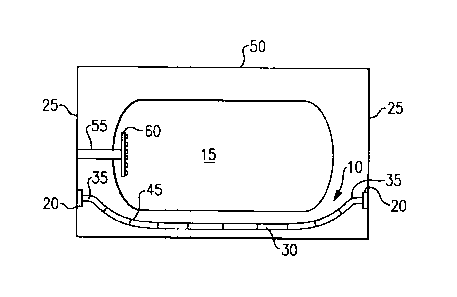
A shower curtain mount has a bracket having a plate for attaching to a surface and a post having a first shaped indentation in an outer surface thereof; an escutcheon covering the plate and having a tube projecting therefrom, the tube encircling the post and maintaining the tube a distance from the post; and, a shower rod having an end portion having second shaped indentation that mates with the first shaped indentation whereby the shower rod is disposed around the post within the distance between the hollow tube and the post.


French Abstract

Un système d'installation d'un rideau de douche comprend une plaque pour l'installation sur une surface et une tringle ayant un premier renfoncement sur sa surface extérieure; une calotte recouvrant la plaque et comportant un tube qui s'en projette, le tube encerclant la tringle et maintenant le tube à distance de la tringle et une tringle de rideau de douche ayant une portion d'extrémité comportant un deuxième renfoncement qui correspond au premier renfoncement par lequel la tringle de rideau de douche est disposée autour de la tige à l'intérieur de la distance entre le tube creux et la tringle.

Claims

Note: Claims are shown in the official language in which they were submitted.


CLAIMS:
1. A shower curtain mounting apparatus, said shower curtain mounting
apparatus
comprising:
a bracket having;
a plate for attaching to a surface, and
a post having a first shaped indentation in an outer surface thereof;
an escutcheon covering said plate and having a tube projecting therefrom, said
tube
encircling said post and maintaining said tube a distance from said post; and
a shower rod having an end portion having a second shaped indentation that
mates
with said first shaped indentation whereby said shower rod is disposed around
said post
within said distance between said tube and said post.
2. The shower curtain mounting apparatus of claim 1 further comprising a
spacer
disposed between said tube and said post to maintain said distance between
said tube and said
post.
3. The shower curtain mounting apparatus of claim 2 wherein said spacer is
an o-ring.
4. The shower curtain mounting apparatus of claim 1 wherein said post
further
comprises a chamfered surface for receiving said shower rod.
5. The shower curtain mounting apparatus of claim 1 wherein said surface is
a wall.
6. The shower curtain mounting apparatus of claim 1 wherein the first
shaped
indentation of the post is a v-shaped groove, and the second shaped
indentation of the shower
rod is a v-shaped indentation.
7. The shower curtain mounting apparatus of claim I wherein there is no
structure
between an outer surface of the post of the bracket and an inner surface of
the tube of the
escutcheon.
5

8. The shower curtain mounting apparatus of claim 1 wherein the shower rod
includes a
curved portion.
6

Description

Note: Descriptions are shown in the official language in which they were submitted.


CA 02735448 2011-03-28
CURVED SHOWER ROD MOUNTING SYSTEM
FIELD OF THE INVENTION
The present disclosure is directed to a shaped shower curtain rod and more
particularly to an apparatus for mounting a shaped shower rod to a shower
wall.
BACKGROUND OF THE DISCLOSURE
In the construction of most bathrooms, it is common to position a shower
nozzle mounted on the wall of an enclosure above a tub or shower basin. Water
splashing out of the enclosure is limited by the use of a shower curtain that
also
defines the enclosure. The shower curtain is ordinarily arranged to drape
loosely
from a set of eyelets or curtain rings that slide along the curtain rod at the
height of
the showerhead or nozzle.
The shower curtain is draped in the bathtub below so that water is not
splashed out of the tub and water hitting the curtain is directed into the
tub. Because
some tubs are elliptical and because bathers demand more elbowroom in their
baths,
curtain rods have evolved into shapes that mimic the shape of the tubs and to
give
bathers more elbow room.
SUMMARY
According to a non-limiting embodiment of the invention, a shower curtain
mounting apparatus has a bracket including a plate for attaching to a surface
and a
post having a first shaped indentation in an outer surface thereof; an
escutcheon
covering the plate and having a tube projecting therefrom, the tube encircling
the
post and maintaining the tube a distance from the post; and, a shower rod
having an
end portion having second shaped indentation that mates with the first shaped
indentation whereby the shower rod is disposed around the post within the
distance
between the hollow tube and the post.
Because the indentations mate and the shower rod does not rotate relative to
the mounting bracket, set screws that are intended to prevent rod rotation,
but tend to
loosen and allow rotation, are eliminated. Because the escutcheon encloses the
shower rod and the bracket, a decorative look is provided for consumers.
1

CA 02735448 2013-02-05
BRIEF DESCRIPTION OF THE DRAWINGS
Figure 1 shows a schematic top view of an embodiment of a shower rod.
Figure 2 shows a schematic view of the shower rod and bracket of Figure 1.
Figure 3 shows a blown-up side view of the shower rod of Figure 2.
DETAILED DESCRIPTION OF THE PREFERRED EMBODIMENT
Referring to Figures 1 and 2, a shower rod 10 disposed over a shower/tub 15
is shown. The shower rod 10 is mounted by a pair of brackets 20 to a pair of
walls 25
(e.g., surfaces. The shower rod 10 has a major shaped portion 30 and, at each
end 35
thereof, a relatively straightened portion that mates with the brackets 20 as
will be
described herein below. A curtain 40 depends from shower rod 10 via rings 45.
The shower/tub is also defined by a back wall 50 that joins the walls 25. A
shower inlet tube 55 joins to a shower head 60 in a manner that is known in
the art.
The shower head 60 is disposed below a top 77 of the shower curtain to ensure
that
water deflected by a bather (not shown) or directed by the shower head 60
falls
against the curtain to be directed into the shower/tub 15 as opposed to out of
the
shower/tub 15.
Referring now to Figures 2 and 3, the bracket 20 is shown with more
particularity. The bracket 20 has a support 65, and an escutcheon 70. The
support 65
has a plate 75 and a transversely extending post 80. The transversely
extending post
80 has a v-shaped groove 85 disposed in a top portion 90 thereof and a base 95
having a shoulder 100 for receiving a spacer such as o-ring 105 as will be
discussed
herein. The base 95 attaches to the plate 75 and extends to the groove 85. The
plate
75 has a pair of openings 110 that receive a screw 115 for mounting into or
through
the wall 25 (see fig.2) via a molly 118 disposed in the drywall or the like.
One of
ordinary skill in the art will recognize that the screw 115 and molly 118 may
be
replaced by a dry wall screw 119 or a similar attachment means. The plate 75
has an
exterior rim 120. The post has a chamfered surface 122 to enable the shower
rod 10
to slip over the post 80.
2

CA 02735448 2013-02-05
The escutcheon 70 has a decorative body 125 having edges 130 that forms an
interference fit over the exterior rim 120 of the plate 75. Though the
decorative body
125 and plate 75 are roughly rectangular with rounded ends, other shapes are
contemplated herein. The decorative body 125 attaches to a transversely
extending
hollow tube 130 that has an inner diameter D that is greater than the outer
diameter
D' of the post 80 and the diameter D" of the shower rod 10. However the
diameter
D" of the shower rod 10 is greater than the diameter D' of the post 80. Given
the
diameters D, D', D", the post 80 fits within the hollow tube 130 and the
shower rod
fits over the post 80 and within the hollow tube 130. The hollow tube 130 may
be
10 attached to the decorative body 125 by any suitable means such as
brazing or the like.
Referring to Figure 2, the shower rod 10 has, at an outer upper end portion
132
thereof, a v-shaped indentation 135 that mates with the v-shaped groove 85 in
the
post 80.
To attach the shower rod 10 to the bracket 20, the plate 75 is fixed to the
wall
25 at a level above the shower head 60. The decorative body 125 of the
escutcheon
70 is inserted over the plate 75 such that the post 80 extends through the
hollow tube
130. The hollow tube 130 engages the o-ring 105 on the post 80 to create a
seal there
between and to ensure a spaced relationship between the hollow tube 130 and
the post
80 into which the shower rod 10 fits. The edge of the escutcheon 70 mates with
the
rim 120 of the plate.
The shower rod 10 is flexed slightly to enable its ends 35 to be inserted over
the post 80 and within the hollow tube 130. The v-shaped indentation 135 of
the
shower rod 10 mates with the v-shaped groove 85 in the post 80 to prevent the
shower
rod 10 from rotating relative to the post 80. No set screws (not shown) are
required.
Though a v-shaped indentation 135 mating with a v-shaped groove 85 is shown,
other
mating shapes that prevent relative rotation between the post 80 and the
shower rod
10 are contemplated herein. The escutcheon 70 ensures that the bracket 20 will
have
a decorative look while the plate 75 and post 80 securely hold the shower rod
10
against rotation.
It should be understood that like reference numerals identify corresponding or
similar elements throughout the several drawings. It should also be understood
that
3

CA 02735448 2013-02-05
although a particular component arrangement is disclosed in the illustrated
embodiment, other arrangements will benefit herefrom.
The foregoing description is exemplary rather than defined by the limitations
within. Various non-limiting embodiments are disclosed herein, however, one of
ordinary skill in the art would recognize that various modifications and
variations in
light of the above teachings will fall within the scope of the appended
claims. For
instance, one of ordinary skill in the art will recognize that other designs
such as
objects, abstracts, architectural features may be substituted for the designs
shown
herein. It is therefore to be understood that with the scope of the appended
claims,
the invention may be practiced other than as specifically described. For that
reason
the appended claims should be studied to determine true scope and content.
4

Representative Drawing
A single figure which represents the drawing illustrating the invention.
Administrative Status

2024-08-01:As part of the Next Generation Patents (NGP) transition, the Canadian Patents Database (CPD) now contains a more detailed Event History, which replicates the Event Log of our new back-office solution.

Please note that "Inactive:" events refers to events no longer in use in our new back-office solution.

For a clearer understanding of the status of the application/patent presented on this page, the site Disclaimer , as well as the definitions for Patent , Event History , Maintenance Fee  and Payment History  should be consulted.

Event History

Description Date
Time Limit for Reversal Expired 2023-09-28
Letter Sent 2023-03-28
Letter Sent 2022-09-28
Letter Sent 2022-03-28
Common Representative Appointed 2019-10-30
Grant by Issuance 2013-09-10
Inactive: Cover page published 2013-09-09
Pre-grant 2013-06-26
Inactive: Final fee received 2013-06-26
Notice of Allowance is Issued 2013-05-15
Letter Sent 2013-05-15
Notice of Allowance is Issued 2013-05-15
Inactive: Approved for allowance (AFA) 2013-05-03
Amendment Received - Voluntary Amendment 2013-02-05
Inactive: S.30(2) Rules - Examiner requisition 2012-10-12
Inactive: Adhoc Request Documented 2012-03-08
Application Published (Open to Public Inspection) 2011-10-13
Inactive: Cover page published 2011-10-12
Inactive: IPC assigned 2011-05-30
Inactive: First IPC assigned 2011-05-30
Inactive: IPC assigned 2011-05-30
Inactive: Filing certificate - RFE (English) 2011-04-12
Letter Sent 2011-04-12
Application Received - Regular National 2011-04-12
Request for Examination Requirements Determined Compliant 2011-03-28
All Requirements for Examination Determined Compliant 2011-03-28

Abandonment History

There is no abandonment history.

Maintenance Fee

The last payment was received on 2013-01-03

Note : If the full payment has not been received on or before the date indicated, a further fee may be required which may be one of the following

  • the reinstatement fee;
  • the late payment fee; or
  • additional fee to reverse deemed expiry.

Patent fees are adjusted on the 1st of January every year. The amounts above are the current amounts if received by December 31 of the current year.
Please refer to the CIPO Patent Fees web page to see all current fee amounts.

Owners on Record

Note: Records showing the ownership history in alphabetical order.

Current Owners on Record
BRASSTECH INC.
Past Owners on Record
IOSIF OVIDIU MANGA
KEVIN WELKER
Past Owners that do not appear in the "Owners on Record" listing will appear in other documentation within the application.
Documents

To view selected files, please enter reCAPTCHA code :


To view images, click a link in the Document Description column. To download the documents, select one or more checkboxes in the first column and then click the "Download Selected in PDF format (Zip Archive)" or the "Download Selected as Single PDF" button.

List of published and non-published patent-specific documents on the CPD .

If you have any difficulty accessing content, you can call the Client Service Centre at 1-866-997-1936 or send them an e-mail at CIPO Client Service Centre.


Document
Description 
Date
(yyyy-mm-dd) 
Number of pages   Size of Image (KB) 
Description 2011-03-27 4 161
Abstract 2011-03-27 1 14
Claims 2011-03-27 1 28
Drawings 2011-03-27 2 39
Representative drawing 2011-09-15 1 5
Description 2013-02-04 4 161
Claims 2013-02-04 2 37
Drawings 2013-02-04 2 48
Representative drawing 2013-08-20 1 5
Acknowledgement of Request for Examination 2011-04-11 1 178
Courtesy - Certificate of registration (related document(s)) 2011-04-11 1 104
Filing Certificate (English) 2011-04-11 1 157
Reminder of maintenance fee due 2012-11-28 1 111
Commissioner's Notice - Application Found Allowable 2013-05-14 1 163
Notice: Maintenance Fee Reminder 2014-12-29 1 121
Notice: Maintenance Fee Reminder 2015-12-29 1 120
Notice: Maintenance Fee Reminder 2016-12-28 1 121
Notice: Maintenance Fee Reminder 2018-01-01 1 120
Notice: Maintenance Fee Reminder 2018-12-30 1 120
Commissioner's Notice - Maintenance Fee for a Patent Not Paid 2022-05-08 1 551
Courtesy - Patent Term Deemed Expired 2022-11-08 1 536
Commissioner's Notice - Maintenance Fee for a Patent Not Paid 2023-05-08 1 550
Correspondence 2013-06-25 1 28