Note: Descriptions are shown in the official language in which they were submitted.
CA 02735584 2011-02-28
WO 2010/028184
PCT/US2009/055940
MATERIAL WITHDRAWAL APPARATUS AND METHODS
OF REGULATING MATERIAL INVENTORY IN ONE OR MORE UNITS
BACKGROUND OF THE INVENTION
Field of the Invention
[0001] Embodiments of the invention generally relate to a material withdrawal
apparatus and method of such. Particularly, the invention relates to material
withdrawal
apparatus and methods of metering and withdrawing one or more materials from
one or
more fluid catalytic cracking (FCC) unit and one or more non-FCC units such as
manufacture of acrylonitrile, as manufacture of pyridine and its derivatives,
and other
industrial processes, etc.
Description of the Related Art
[0002] FIG. 1 is a simplified schematic of a conventional fluid catalytic
cracking system
130. The fluid catalytic cracking system 130 generally includes a fluid
catalytic
cracking (FCC) unit 110 coupled to a catalyst injection system 100, a
petroleum feed
stock source 104, an exhaust system 114 and a distillation system 116.
[0003] The FCC unit 110 includes a regenerator 150 and a reactor 152. The
reactor 152
primarily houses the catalytic cracking reaction of the petroleum feed stock
and delivers
the cracked product in vapor form to the distillation system 116. Spend
catalyst from
the cracking reaction is transfer from the reactor 152 to the regenerator 150
to
regenerate the catalyst by removing coke and other materials. The rejuvenated
catalyst
is reintroduced into the reactor 152 to continue the petroleum cracking
process to bum
off coke from the catalyst. The regenerated catalyst is then reintroduced into
the reactor
152 to continue the petroleum cracking process.
[0004] The fluid catalytic cracking system generally includes a FCC unit
coupled to a
catalyst injection system 100 that maintains a continuous or semi continuous
addition of
fresh catalyst to the inventory circulating between a regenerator and a
reactor.
[0005] During the catalytic process, there is a dynamic balance of the total
catalyst
within the FCC unit. For example, catalyst is periodically added utilizing the
catalyst
injection system and some catalyst is lost in various ways such as through the
distillation system, through the effluent exiting the regenerator, etc.
CA 02735584 2011-02-28
WO 2010/028184
PCT/US2009/055940
[0006] If the amount of catalyst within the FCC unit diminishes over time, the
performance and desired output of the FCC unit will diminish, and the FCC unit
will
become inoperable. Conversely, if the catalyst inventory in the FCC unit
increases over
time or becomes deactivated, the catalyst bed level within the regenerator
reaches an
upper operating limit and the deactivated or excess catalyst is withdrawal to
prevent
unacceptably high catalyst emissions into the flue gas stream, or other
process upsets.
[0007] Thus, there is a need for a material withdrawal apparatus suitable for
withdrawing materials from one or more units, like FCC units.
BRIEF DESCRIPTION
[0008] The purpose and advantages of embodiments of the invention will be set
forth
and apparent from the description of exemplary embodiments that follows, as
well as
will be learned by practice of the embodiments of the invention. Additional
advantages
will be realized and attained by the methods and systems particularly pointed
out in the
written description and claims hereof, as well as from the appended drawings.
[0009] An embodiment of the invention provides a material withdrawal
apparatus. The
material withdrawal apparatus includes a heat exchanger and a sensor. The heat
exchanger includes a material inlet, material outlet, cooling fluid inlet, and
cooling fluid
outlet. The material inlet is coupled to at least a unit and the sensor is
coupled to the
heat exchanger to provide a metric indicative of the temperature at the
material inlet;
material outlet; cooling fluid inlet and cooling fluid outlet.
[0010] A second embodiment of the invention provides a material withdrawal
apparatus
having a vessel suitable for high temperature operation. The vessel includes
an outer
wall, a liner, a fill port and a discharge port. The liner comprises a heat
insulating
refractory material. The liner at least partially covers the inner surface of
the outer wall
and the liner comprising a heat insulating refractory material. The fill port
and discharge
port are defined in the vessel and the fill port is configured to receive
withdrawn
material from at least a unit.
[0011] A third embodiment provides a method. The method includes: withdrawing
material from a unit to a heat exchanger coupled to the unit; wherein the heat
exchanger
has a material inlet; a material outlet; a cooling fluid inlet and a cooling
fluid outlet with
respective temperatures; measuring the respective temperatures at the material
inlet;
2
CA 02735584 2011-02-28
WO 2010/028184
PCT/US2009/055940
material outlet; cooling fluid inlet and cooling fluid outlet of the heat
exchanger;
determining a change in temperature between the material inlet and material
outlet and
determining a change in temperature between the cooling fluid inlet and
cooling fluid
outlet; and correlating the change in temperature between the material inlet
and material
outlet and the change in temperature between the cooling fluid inlet and
cooling fluid
outlet to a metric of material withdrawn from the unit.
[0012] A fourth embodiment provides a method. The method includes: withdrawing
material from a unit into vessel coupled to at least a unit; and measuring the
metric of
material withdrawn into the vessel. The vessel includes an outer wall, a
liner, a fill port
and a discharge port. The liner comprises a heat insulating refractory
material. The
liner at least partially covers the inner surface of the outer wall and the
liner comprising
a heat insulating refractory material. The fill port and discharge port are
defined in the
vessel and the fill port is configured to receive withdrawn material from at
least a unit.
[0013] A fifth embodiment provides a system. The system includes a unit
coupled to a
material withdrawal apparatus. Material withdrawal apparatus includes at least
a
member selected from a group consisting of heat exchanger, a vessel, and
combinations
thereof. The heat exchanger includes a material inlet, material outlet,
cooling fluid inlet,
and cooling fluid outlet. The material inlet is coupled to at least a unit and
the sensor is
coupled to the heat exchanger to provide a metric indicative of the
temperature at the
material inlet; material outlet; cooling fluid inlet and cooling fluid outlet.
The vessel
includes an outer wall, a liner, a fill port and a discharge port. The liner
comprises a
heat insulating refractory material. The liner at least partially covers the
inner surface of
the outer wall and the liner comprising a heat insulating refractory material.
The fill port
and discharge port are defined in the vessel and the fill port is configured
to receive
withdrawn material from at least a unit.
DESCRIPTION OF THE DRAWINGS
[0014] The accompanying figures, which are incorporated in and constitute part
of this
specification, are included to illustrate and provide a further understanding
of the
method and system of the invention. Together with the description, the
drawings serve
to explain the principles of the invention.
3
CA 02735584 2011-02-28
WO 2010/028184
PCT/US2009/055940
[0015] FIG.1 is a schematic diagram of a conventional material withdrawal
apparatus in
accordance with an embodiment of the present invention;
[0016] FIG.2 is a schematic diagram of a material withdrawal apparatus in
accordance
with an embodiment of the present invention;
[0017] FIG.3 is schematic diagram detailing a heat exchanger in accordance
with an
embodiment of the present invention;
[0018] FIG.4 is another schematic diagram of a heat exchanger with a seal in
accordance with an embodiment of the present invention;
[0019] FIG.5 is another schematic diagram of a heat exchanger with a seal in
accordance with an embodiment of the present invention;
[0020] FIG.6 is a schematic diagram of a material withdrawal apparatus with a
delivery
vessel in accordance with an embodiment of the present invention;
[0021] FIG.7 is a flow diagram of a method of regulating material in at least
one unit in
accordance with an embodiment of the present invention; and
[0022] F1G.8 is a flow diagram of another method of regulating material in at
least one
unit in accordance with an embodiment of the present invention
[0023] To facilitate understanding, identical reference numerals have been
used, where
possible, to designate identical elements that are common to the figures,
except that
suffixes may be added, when appropriate, to differentiate such elements. The
images in
the drawings are simplified for illustrative purposes and are not depicted to
scale. It is
contemplated that features or steps of one embodiment may be beneficially
incorporated
in other embodiments without further recitation.
DETAILED DESCRIPTION
[0024] In the following description, like reference characters designate like
or
corresponding parts throughout the several views shown in the figures. It is
also
understood that terms such as "top," "bottom," "outward," "inward," and the
like are
words of convenience and are not to be construed as limiting terms.
[0025] Reference will now be made in detail to exemplary embodiments of the
invention which are illustrated in the accompanying figures and examples.
Referring to
the drawings in general, it will be understood that the illustrations are for
describing a
4
CA 02735584 2011-02-28
WO 2010/028184
PCT/US2009/055940
particular embodiment of the invention and are not intended to limit the
invention
thereto.
[0026] Whenever a particular embodiment of the invention is said to comprise
or
consist of at least one element of a group and combinations thereof, it is
understood that
the embodiment may comprise or consist of any of the elements of the group,
either
individually or in combination with any of the other elements of that group.
Furthermore, when any variable occurs more than one time in any constituent or
in
formula, its definition on each occurrence is independent of its definition at
every other
occurrence. Also, combinations of substituents and/or variables are
permissible only if
such combinations result in stable compounds.
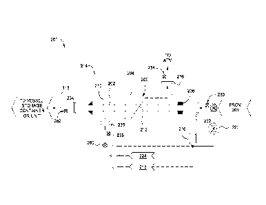
[0027] FIG. 2 is a schematic representation of an embodiment of a material
withdrawal
system 200 for removing one or more types of materials from one or more units
201.
The material withdrawal apparatus includes a heat exchanger 214 and one or
more
sensors 280, 282, 284, 286 and 290. The heat exchanger 214 includes one or
more
material inlets 232, one or more material outlets 234, one or more cooling
fluid outlets
236, and one or more cooling fluid inlets to 238. The material inlet coupled
to at least a
unit 201 so that material from the unit 201 may be passed through the heat
exchanger
214 and cooled prior to exiting the heat exchanger 214 through the material
outlet 234.
The material passing through the heat exchanger 214 is cooled by a cooling
fluid
entering the heat exchanger 214 through the cooling fluid inlet 232 and
exiting the heat
exchanger 214 through the cooling fluid outlet 234.
[0028] In one embodiment, heat exchanger 214 includes a plurality of sensors
such as
one or more material inlet temperature sensors 280, one or more material
outlet
temperature sensors 282, one or more cooling fluid outlet temperature sensors
284, and
one or more cooling fluid inlet temperature sensor 286 to respectively provide
metrics
indicative of the temperatures at the material inlet 232, material outlet 234,
cooling fluid
inlet 238, and cooling fluid outlet 236. The temperature at the material inlet
232 is
indicative of the temperature of the material entering the heat exchanger 214
from the
unit 201. The temperature at the material outlet 234 is indicative of the
temperature of
the material exiting the heat exchanger 214. The temperature at the cooling
fluid inlet
238 is indicative of the temperature of cooling fluid entering the heat
exchanger 214
while temperature at the cooling fluid outlet 236 is indicative of the
temperature of
CA 02735584 2011-02-28
WO 2010/028184
PCT/US2009/055940
cooling fluid exiting the heat exchanger 214. Non-limiting examples of
temperature
sensors, for illustration and not limitation, include Thermocouples, Pt
Resistance
Thermometers, and IR cameras, either individually or in a combination of two
or more
thereof Pt Resistance Thermometers measure temperature based on changes in
electrical
resistance of Platinum (Pt) at different temperatures. IR cameras use the
measurement of
infrared light emissions to measure the temperature of an object. In one
embodiment,
cooling fluid outlet to 236 and the material inlet 232 are located at one end
of the heat
exchanger 214 while the cooling fluid inlet 238 and the material outlet 234
are located
at the opposite end of the heat exchanger 214.
[0029] The sensor 290 is configured to provide a metric indicative of the
amount of
cooling fluid passing through the heat exchanger 214. The sensor 290 may be
interfaced
with at least one of the conduits coupled to the cooling fluid outlet 236 or
the cooling
fluid inlet 238. Alternatively, the sensor 290 may be interfaced with the heat
exchanger
214 to determine the amount of cooling fluid passing through the heat
exchanger 214.
In the embodiment depicted in FIG. 2, the sensor 290 is a flow meter
interfaced with the
conduit supplying cooling fluid to the cooling fluid inlet 238.
[0030] The mass or quantity of withdrawn materials from the unit 201 may be
derived
using the temperature information obtained from the withdrawn material and
cooling
fluid passing through the heat exchanger 214 using a heat balance model. In
one
embodiment, since the mass or quantity of withdrawn material from the unit is
measured by a heat balance around the heat exchanger system, a separate weight
measuring vessel or other equipment for determining the amount of material
withdrawn
from the unit 201 is not required such that the material withdrawal system 200
is
substantially free of a vessel utilized for measuring material (i.e., a
metering vessel). In
another embodiment, a withdrawn material flows from a unit 201 through the
heat
exchanger 214 and then through a delivery line 118 which connects the heat
exchanger
214 to a vessel. The vessel may be a simple storage or shipping container, or
a metering
vessel which can be used for redundancy or calibration of the heat balance.
Thus, in one
embodiment, the delivery line 118 delivers withdrawn cooled material from the
heat
exchanger to the vessel. It should be appreciated that the material withdrawal
apparatus
200 may be used in units or processes which have varying degree of specificity
in
metered the amount of withdrawn material. Thus, depending upon the specificity
of
6
CA 02735584 2011-02-28
WO 2010/028184
PCT/US2009/055940
calculating the amount of withdrawn material, the mass or quantity of
withdrawn
material from the unit (i.e. the catalyst cooled and transferred to the spent
catalyst
hopper) may be calculated by a heat balance around the heat exchanger system
by the
use of the following equation, with or without a metering vessel:
Mass of cooling fluid X Specific Heat of cooling fluid X (temperature of
cooling fluid
at cooling fluid outlet - temperature of cooling fluid at cooling fluid inlet)
= Mass of
material X Specific heat of material X (temperature of material at material
inlet -
temperature of material at material inlet); wherein temperature of cooling
fluid at the
cooling fluid outlet may be derived from information from the sensor 284,
wherein
temperature of cooling fluid at the cooling fluid inlet may be derived from
information
from the sensor 286, wherein temperature of material at the material outlet
may be
derived from information from the sensor 282, wherein temperature of material
at the
material inlet may be derived from information from the sensor 280. In one
embodiment, the material is catalyst or other material withdrawn from unit
201. In one
embodiment, the cooling fluid is air or other suitable cooling fluid. The mass
of
cooling fluid may be derived from information obtained from the sensor 290. It
is
contemplated that the a metric of the amount of material being passed through
a heat
exchanger may be determined using the heat balance described above utilizing
heat
exchangers of other types and/or having other configurations.
[00311 In one embodiment, the heat exchanger 214 includes a first conduit 202
and a
housing 204. Material (i.e. catalyst) flows from the unit 201 via the conduit
202 and a
coolant is circulated through the coolant volume 206 defined between the first
conduit
202 and the housing 204 to extract heat from the material in the first conduit
202. In one
embodiment, the first conduit 202 of the heat exchanger 214 is substantially
non-
tortuous and substantially free of bends or curves. It should be noted that
some bends or
curves may exist. In one embodiment, the first conduit 202 is substantially
non-tortuous
and free of bends or curves to an amount of less than about 10% by surface
area. hi
another embodiment, the first conduit 202 is substantially non-tortuous and
free of
bends or curves to an amount of less than about 5% by surface area. In a
particular
embodiment, the first conduit 202 is substantially non-tortuous and free of
bends or
curves to an amount of less than about 1% by surface area. In one embodiment,
the first
conduit 202 of the heat exchanger is substantially linear. In a particular
embodiment,
7
CA 02735584 2011-02-28
WO 2010/028184
PCT/US2009/055940
first conduit 202 is substantially linear up to about 99%, up to about 95%, up
to about
90%, up to about 85%, up to about 80%, and up to about 75%.
[0032] "Substantially free" of bends or 'substantially linear' expressly
allows the
presence of trace amounts on non-linear surfaces and is not to be limited to a
specified
precise value, and may include values that differ from the specified value. In
one
embodiment, "substantially free" expressly allows the presence of trace
amounts of non-
linear surfaces. In a particular embodiment, "substantially free" expressly
allows the
presence of trace amounts of non-linear circumference, area, or volume, in
respectively
continuous or discrete fashion, such that the total circumference, area, or
volume of a
first conduit 202 is substantially non-tortuous and free of bends or curves by
less than
about 10%, by less than about 5%, by less than about 1%, by less than about
0.5%, and
less than about 0.1 %. "Substantially free" expressly allows the presence of
the
respective trace amounts of non-linear surfaces, etc. but does not require the
presence
non-linear surfaces, such as bends or curves.
[0033] Approximating language, as used herein throughout the specification and
claims,
may be applied to modify any quantitative or qualitative representation that
could
permissibly vary without resulting in a change in the basic function to which
it is
related. Accordingly, a value modified by a term such as "less than about" or
"substantially free of' is not to be limited to a specified precise value, and
may include
values that differ from the specified value. In at least some instances, the
approximating
language may correspond to the precision of an instrument for measuring the
value.
Furthermore, "withdrawal of material" may be used in combination with a term,
and
include a varying amount of withdrawn material and is not to be limited to a
specified
precise value, and may include values that differ from a specified value.
[0034] In one embodiment of the heat exchanger 214, the housing 204 includes a
tube
maintained at a spaced apart relation from the first conduit 202. The shape
and size of
the housing may vary and is adjustable based on intended use. The first
conduit 202
includes one or more protrusions 210 to hold the first conduit in spaced apart
relation
relative to the housing. In one embodiment, the protrusion 210 is unattached
to the
housing 204 to allow the longitudinal expansion of the conduit 202 relative to
the
housing 204. In one embodiment, the heat exchanger 214 includes a first
conduit 202
8
CA 02735584 2011-02-28
WO 2010/028184
PCT/US2009/055940
and a housing 204 wherein the housing 204 wraps around the first conduit 202
like a
helix.
[0035] The shape and size of the protrusions 210 or housing 204 may vary. For
illustration and not limitation, the protrusions 210 may be in the shape of a
sphere, fiber,
plate, cube, tripod, pyramid, rod, tetrapod, fins, studs, etc, either
individually or in a
combination thereof. In one embodiment, protrusions 210 include fins, studs or
other
geometric shape extending into the coolant volume 206 defined between the
housing
204 and the first conduit 202 that increases the heat transfer area.
Properties of each
protrusion 210 may be selected independent of any other protrusions 210. For
example,
the dimensions of each protrusion 210, including, for example, such dimensions
as
depth, width, length and shape, may independently vary from embodiment to
embodiment and FIG. 2 depicts the protrusion 210 as studs or fins for
illustration only.
The size of the protrusions 210 also may vary and can depend on its heat
exchanger and
intended use.
[0036] In one embodiment, the heat exchanger 214 has an operational
temperature
range from about ambient to 870 "C. The sliding seal and the coupled
protrusions 210
allow the first conduit 202 to expand longitudinally relative to the housing
204 over
such operational temperatures. The heat exchanger 214 may further comprise a
coolant
fluid (i.e. cooling fluid) path 212 extending through the coolant volume. The
coolant
fluid path may be coupled to a blower 224, a source of cooling fluid 216 (such
as plant
air or other suitable fluid), or an eductor 218, either individually or in
combination
thereof. The sensor 290 may be interfaced with the coolant fluid path 212 to
obtain a
metric indicative of the mass of cooling fluid flowing through the heat
exchanger 214
for use in the heat balance computation. Non-limiting examples of coolant
fluid
include but is not limited to, air, low pressure water, high pressure water,
nitrogen, inert
gas, heat transfer fluids such as phenoxybenzene, phenylbenzene (also known by
DowthermTM) 1,1'-Biphenyl, chloro derivatives (also known by Santothermlm,)
steam.
[0037] In one embodiment, coolant fluid includes coolant fluids which minimize
boiling such as high pressure water In one embodiment, the sensor 290 may
provide a
coolant flow rate that may be measured by such as but not limited to turbine
meter,
positive displacement meter, orifice meter, pitot tube, Venturi meter,
magnetic flow
9
CA 2735584 2017-04-13
meter, mass flow meter etc., either individually or in a combination of two or
more thereof.
[0038] In one non-limiting embodiment, a plurality of material inlets 232 are
respectively coupled to a plurality of units 201. In another non-limiting
embodiment,
the plurality of material inlets 232 are respectively coupled to a plurality
of units 201
in parallel. In a particular non-limiting embodiment, at least one of the
material inlets
232 is selectively coupled to a plurality of units 201.
[0039] In one non-limiting embodiment, a plurality of heat exchangers 214 may
be
serially coupled to a single unit 201. In one non-limiting embodiment, a
plurality of
heat exchangers 214 may be coupled in parallel to an outlet of a single unit
201. In
another non-limiting embodiment, a plurality of heat exchangers 214 are
respectively
coupled to a plurality of units 201.
[0040] In another embodiment of a material withdrawal apparatus 200, a
plurality of
material inlets 232 are respectively coupled to a unit 201in parallel. In
another
embodiment, a material inlet 232 is alternatively coupled to a plurality of
units 201 by
a diverter valve.
[0041] In an embodiment, the material withdrawal apparatus 200 are configured
to
withdraw material from one or more units 201, such as but not limited to, an
FCC unit,
fixed bed or moving bed unit, bubbling bed unit, units suitable for the
manufacture of
pyridine and its derivatives, units suitable for the manufacture of
acrylonitrile, and
other units suitable for industrial processes, etc., either individually or in
a combination
of two or more. In a particular embodiment, the material withdrawal apparatus
200
may be configured to withdraw material from a plurality of units 201 that are
FCC
units. In such embodiment, the material withdrawal apparatus may have an
operational
pressure of about 0 to about 100 pounds per square inch. The FCC unit is
adapted to
promote catalytic cracking of petroleum feed stock provided from a source and
may be
configured in a conventional manner. One example of a material withdrawal
apparatus
that may be adapted to benefit from the invention is described in United
States Patent
Application Number 11/184,125, filed July 19, 2005. Another example of a
material
withdrawal apparatus that may be adapted to benefit from the invention is
described in
United States Patent Application Serial Number 61/026,343 filed February 5,
2008.
CA 02735584 2016-10-05
In one embodiment, the material withdrawal apparatus 200 is configured to
withdraw material from the plurality of units 201 through material inlet 232.
In another
embodiment, the material withdrawal apparatus 200 is configured to withdraw
material
from units designed to crack gasoline into Liquefied Petroleum Gas (LPG) such
as but
not limited to SuperflexTM process or crack heavy feed into LPG instead of
gasoline
such as but not limited to Indmaxm4 process or. In another particular
embodiment, the
material withdrawal apparatus 200 may be configured to withdraw material from
a unit
201for processing acrylonitrile. The material withdrawal apparatus has at
least one
material inlet 232 adapted for coupling to the unit 201. An example of a unit
201
suitable for the manufacture of acrylonitrile is a fluidized bed process.
Similar units are
also used for manufacturing other chemicals such as pyridine.
[00421 The embodiments of the material withdrawal apparatus 200 are configured
to
withdraw various materials and embodiments of the invention are not limited by
what
material is being withdrawn or the form of the material being withdrawn.
Examples of
compositions of material include but are not limited to alumina, silica,
zirconia,
aluminosilicates, etc., either individually or in a combination of two or more
compositions. Non-limiting examples of the form of material include liquid,
powder,
formed solid shapes such as microspheres, beads, and extrudates, either
individually or
in a combination of two or more forms. Non-limiting examples of materials may
be
referred as and include catalyst, product, powder, additive, equilibrium spent
catalyst,
and catalyst fines. Non-limiting examples of material withdrawal apparatus
include a
suitably adapted material addition vessel such as a pressurized vessel, a
batching vessel
for delivering as liquid, powders, and formed solid shapes such as
microspheres, beads,
and extrudes, either individually or in a combination of two or more.
[0043] Embodiments of the heat exchanger 214 include, but are not limited to,
as
described above. In one embodiment of the heat exchanger, a housing confines a
coolant volume around at least a portion of the conduit; and a sliding seal
208 seals the
housing to the conduit in a manner that allows the first conduit to expand
longitudinally
relative to the housing. Non-limiting embodiments of sliding seal are
described in FIG.
3-5.
11
CA 02735584 2011-02-28
WO 2010/028184
PCT/US2009/055940
[0044] FIG 3. includes an embodiment of the sliding seal 208. The sliding seal
208
includes a seal housing 304, a retainer 306, and a seal 308. The seal housing
204 is
coupled to an end cap 204.
[0045] FIG. 4 includes another embodiment of a sliding seal 400. The sliding
seal 400
couples a first portion 402 of the housing to a second portion 404 of the
housing. The
sliding seal 400 includes a sleeve 406, seal housing 408, a retainer 410, and
a seal 412.
The sleeve 406 is welded, brazed or otherwise fastened or connected in a
substantially
leak free manner to the first portion 402 of housing. The seal housing 408 is
coupled to
the sleeve. 406. The retainer 410 is threaded into the seal housing 408 to
retain the seal
against the first conduit 202.
[0046] FIG.5. includes another embodiment of a sliding seal 500. The sliding
seal
includes one or more bellows 502. The bellows 502 couples the first portion
402 of the
housing to the second portion 404 of the housing.
[0047] The material withdrawal apparatus 200 may also include a gas source 216
coupled to the first conduit 202 of the heat exchanger 214. The air or other
gas source
216 may be utilized to fluidize, aerate and/or otherwise cool the withdrawn
material
disposed in the vessel. The material withdrawal apparatus may also include a
dynamic
control valve 220 to control the amount of gas delivered from the gas source
into the
first conduit. In one embodiment, the flow of material through heat exchanger
is
maintained at a rate from about 1 meter/second to about 10 meters/second. In
another
embodiment, the flow of material through heat exchanger is at a rate from
about 1
meter/second to about 5 meters/second. In a particular embodiment, the flow of
material through heat exchanger is at a rate of about 3 meters second, with a
tolerance of
up to about +/-30%. In another embodiment, the flow of material through heat
exchanger is at a rate of about 3 meters second, with a tolerance of up to
about +/-20%.
In yet another embodiment, the flow of material through heat exchanger is at a
rate of
about 3 meters second, with a tolerance of up to about +/-10%.
[0048] In another embodiment, as depicted in Figure 6, a material withdrawal
apparatus
600 includes a vessel 602 suitable for high temperature operation. The vessel
602
includes an outer wall 610, liner 620, fill port 104 and a discharge port 106.
The liner
620 at least partially covers the inner surface of the outer wall 610. The
fill port and
12
CA 02735584 2011-02-28
WO 2010/028184
PCT/US2009/055940
discharge port are defined in the vessel. The fill port is configured to
receive withdrawn
material from one or more units 201.
[0049] Cooling fluid may be provided to the bottom of the vessel such that the
cooling
fluid bubbles up through and cools the material disposed in the vessel. The
cooling
fluid, such as air or other suitable fluid, may be distributed among the
withdrawn
material in the vessel 602 to cool the withdrawn material. The source of
coolant may be
a blower 224 or source of cooling fluid 216 (for example, a source of plant
air).
[0050] In one embodiment, cooling coils to be used within the vessel to
distribute the
cooling fluid among the material; any of the coolant fluids mentioned above,
either
individually or in combination of two or more, can be used, when the one or
more
coolant fluids are circulated through the cooling coils. The cooling coils may
by a
closed loop system (e.g., a system that prevents contact between the cooling
fluid and
the material disposed within the vessel) or an open system (e.g., a system
that allows
direct contact between the material disposed within the vessel and a cooling
fluid
suitable for contact with the material). Non-limiting examples of coolant
fluid include
but is not limited to, air, low pressure water, high pressure water, nitrogen,
inert gas,
heat transfer fluids such as phenoxybenzene, phenylbenzene (also known by
DowthermTm) 1,1'-Biphenyl, chloro derivatives (also known by SantothermTm,)
steam,
etc. either individually or in combination of two or more thereof.
[0051] In one embodiment, the material withdrawal apparatus 600 further
includes a
metering device 256 coupled to the fill port 104 to monitor or control the
amount of
material received from one or more units 201. The metering device 256 may be
an
on/off valve such as an everlasting valve, a rotary valve or other device
suitable for
regulating the amount of material withdrawn from the unit 201 into the vessel
602. The
metering device 256 may determine the amount of material by weight, volume,
timed
dispense or by other manners. The material requirements of a unit 201 may
vary. In one
embodiment wherein the unit 201 is an FCC unit, the metering device 256 is
typically
configured to remove about 0.1 to about 30 tons per day of catalyst from the
regenerator
150 without interruption of processing in the FCC unit. The metering device
256
typically removes catalysts from the FCC unit periodically over the course of
a planned
production cycle, typically 24 hours, in multiple shots of predetermined
amounts spaced
13
CA 02735584 2011-02-28
WO 2010/028184
PCT/US2009/055940
over the production cycle. However, catalysts may also be removed from the FCC
unit
in an "as needed" basis as discussed above.
[0052] In the embodiment, the metering device 256 is a control valve that
regulates the
amount of material delivered from a unit 201 into the storage vessel 602 by
timed
actuation. The control valve may include shear disk (not shown) for opening
and
closing a valve orifice. In one embodiment, the shear disk rotates
eccentricity while
additionally rotating clear of the orifice to provide a self-lapping, seat
cleaning action
that prevents the withdrawn catalyst from grooving the sealing surfaces of the
shear disk
and valve seat that could cause the valve leakage. One valve that may be
adapted to
benefit from the invention is available from the Everlasting Valve Company,
located in
South Plainfield, New Jersey. Other control valves may alternatively be
utilized.
[0053] The metering device 256 is opened when the vessel 602 is at a pressure
less than
the unit 201 to allow withdrawn material to flow into the interior of the
vessel. In one
embodiment, vent control valves 690, 692 may be opened to vent the vessel to
atmosphere through a filter 116 while the vessel 602 is being filled through
the metering
device 256.
[0054] An outlet valve 260 is coupled to the discharged port 106 to control
the amount
of withdrawn catalyst removed from the vessel 602 to the spent catalyst
storage/disposal
(not shown) through an outlet line 694. In one embodiment, the outlet valve
260 is
opened after the withdrawn catalyst residing in the vessel 602 has cooled to a
predetermined or has resided in the vessel 602 for a predetermined period of
time
sufficient to allow the temperature of the withdrawn catalyst to reach a
temperature
suitable of handling outside of the vessel 602. The predetermined period of
time may
be set or adjusted by the controller 120 controlling the operation of the
outlet valve 260.
[0055] In one embodiment, the control valve of the metering device 256 and the
outlet
valve 260 are interlocked to prevent simultaneous opening. This allows data to
be
obtained between valve openings such that the amount of catalyst entering and
leaving
the vessel 602 may be accurately resolved. In one embodiment, the outlet valve
260 is
opened while a flow control circuit 108 provides air at about 60 psi (about
4.2 kg/cm2)
into the interior of the vessel 602 to cause catalyst to flow from the vessel
602 through
the valve 260 and into the spent catalyst storage/disposal via the outlet port
106.
Embodiments of the invention also include the outlet valve 260 being opened
while the
14
CA 02735584 2011-02-28
WO 2010/028184
PCT/US2009/055940
flow control circuit 108 provides other gas such as nitrogen or inert gas,
either
individually or in a combination thereof.
[0056] In one embodiment, the material withdrawal apparatus 600 further
includes one
or more heat exchangers 214, and one or more delivery lines 118. The delivery
line 118
is coupled to the inlet 104 for delivering withdrawn material from one or more
units 201
to the vessel 602.
[0057] In one embodiment, the liner 620 comprises heat insulating refractory
material.
Examples of heat insulating refractory material include one or more materials
such as
but not limited to oxides of aluminum (alumina), silicon (silica), magnesium
(magnesia),calcium (lime), Zirconia, either individually or in a combination
of two or
more thereof. In one embodiment, the insulating refractory material comprises
a
thickness from about 25 mm to about 125 mm. In another embodiment, the
insulating
refractory material comprises a thickness from about 50 mm to about 100 mm. In
yet
another embodiment, the insulating refractory material comprises a thickness
from
about 75 mm to about 100 mm. An example of insulating refractory material is
Resco
Cast 17ECTM. Resco Cast 17EC may have a thickness from about 50 mm to about
100
mm.
[0058] Embodiments of the invention are also not limited by what the heat
insulating
refractory material is and is also not limited by the amount, thickness, or
form of the
heat insulating refractory material. What the heat insulating refractory
material is and
the amount, thickness, or form of the heat insulating refractory material may
readily be
adjusted according to the conditions and application of the vessel 602. For
example, in
one embodiment, heat insulating refractory material includes capability of
withstanding
extremely high temperatures such as such as but not limited to oxides of
aluminum
(alumina), silicon (silica), magnesium (magnesia),calcium (lime), Zirconia,
either
individually or in a combination of two or more thereof.
[0059] In one embodiment, the liner 620 may comprise a thickness based on one
or
more liners. In other embodiments, the liner 620 may comprise a thickness
based on two
or more different types of liners such as a first outer liner 622 and a second
inner liner
624. Thus, the liner 620 may comprise multilayers wherein the first and the
second
liner are the same or differ from each other. In one embodiment, the inner
liner 624
comprises abrasion resistant material suitable for use at temperatures in
excess of 600r.C.
CA 02735584 2011-02-28
WO 2010/028184
PCT/US2009/055940
An example of abrasion resistant material includes but is not limited to Resco
AA
22STM. Embodiments of the invention are not limited by what the abrasion
resistant
material is and is also not limited by the amount, thickness, or form of the
abrasion
resistant material. In a particular embodiment, liner 620 comprises a first
inner liner 624
comprising a thin layer of abrasion resistant material suitable for use at
temperatures in
excess of 600*C and second outer liner 622 comprising a thicker layer of heat
insulating
refractory material.
[0060] In one embodiment, the outer wall 610 includes one or more materials
such as
but not limited to carbon steel. The outer wall 610 may be a carbon steel in
the form of
a jacket around the liner 620. In one embodiment, the outer wall 610 has a
metallic
surface. The outer wall 610 may include one or more metals, such as but not
limited to,
Au, Ag, Cu, Ni, Pd, Pt, Al, and Cr, either individually or through any
combination
thereof. In another embodiment, the outer wall 610 may include iron, nickel,
cobalt,
manganese, tin, vanadium, nickel, titanium, chromium, manganese, cobalt,
germanium,
bismuth, molybdenum, antimony, and vanadium, either individually or in a
combination
of two or more thereof.
[0061] In one embodiment, the outer wall 610 comprises a thickness from about
25 mm
to about 50 mm. In another embodiment, the outer wall 610 comprises a
thickness from
about 9 mm to about 50 mm. In yet another embodiment, the outer wall 610
comprises a
thickness from about 9 mm to about 16 mm. In one embodiment, the outer wall
610
may comprise a thickness based on multiple layers, which are the same or
differ from
each other.
[0062] Embodiments of the invention are not limited by what the outer wall 610
is and
is also not limited by the amount, thickness, or form of the outer wall. What
the outer
wall 610 is and the amount, thickness, or form of the outer wall 610 may
readily be
adjusted according to the conditions and application of the vessel 602. For
example, in
one embodiment, the outer wall 610 is capable of withstanding extremely high
temperatures and the outer wall 610 thicknesses may be varied based on vessel
diameter 630 and design pressures of the vessel 602 as shown in table 1:
16
CA 02735584 2011-02-28
WO 2010/028184
PCT/US2009/055940
Table 1
3.5 kg/cm2 3.5 kg/cm2 8.6 kg/cm2 8.6 kg/cm2
Elliptical Elliptical
Diameter Head Shell Head Shell
1 m 9 mm 9 mm 9 mm 9 mm
2m 12 mm 12 mm 12 mm 12 mm
16 mm 16 mm
3m 16 mm 16 min
[0063] The liner 620 may comprise a thickness based on one type of lining in
one
embodiment. In other embodiments, liner 620 may comprise a thickness based on
two
or more different types of lings, such as a first liner 622 and a second liner
624. Thus,
the liner 620 may comprise multilayer coatings wherein the first and the
second liners
are the same or differ from each other.
[0064] In one embodiment, the material withdrawal apparatus 600 further
includes a
control valve 220 configured to control the amount of gas to the delivery
line118 and
entrained with the material. In a particular embodiment, the material
withdrawal
apparatus 600 optionally includes one or more heat exchanger 214 and or one or
more
flow control circuits 108 coupled to the vessel.
[0065] In one embodiment, material withdrawal apparatus 600 further includes a
flow
control circuit 108 configured to dynamically regulate backpressure within the
vessel
602 to control the flow of material into the vessel 602 from the unit 201.
Advantages of
positioning of the flow control circuit 108 downstream of the vessel 602 may
include,
but is not restricted to, preventing abrasive material contacting with the
flow control
circuit 108, and preventing dust emissions to atmosphere. For example, the
flow control
circuit 108 may increase the pressure within the vessel 602 such that the rate
of material
entering the vessel through the fill port 104 is slowed. Conversely, the flow
control
circuit 108 may reduce the pressure within the vessel to allow more material
to flow into
the vessel 602 through the fill port 104. When flow control circuit 108 used
in
conjunction with a heat exchanger 214 coupled to the fill port 104, the amount
of
cooling of the material passing through the heat exchanger 214 into the vessel
602 may
17
CA 02735584 2011-02-28
WO 2010/028184
PCT/US2009/055940
be controlled and additionally, the rate of material flowing through the
conduit 118 may
be controlled to prevent settling of material in the conduit 118 and clogging.
Additionally, the flow control circuit 108 may be coupled to a controller 120,
such that
the pressure of the vessel 602 is dynamically regulated in response to at
least one of the
amount of material in the vessel 602, the rate of material passing through the
heat
exchanger 214 and the temperature of the material exiting the heat exchanger
214.
[0066] In one embodiment, the vessel 602 is suitable for high temperature
operation. In
a particular embodiment, the vessel 602 is suitable for receiving catalyst at
a
temperature in excess of about 600 C. In another embodiment, the vessel 602
is
suitable for receiving material at a temperature in a range from about 600 C
to about
850 C. In yet another embodiment, the vessel 602 is suitable for receiving
material at a
temperature in excess of about 800 C. In yet another embodiment, the vessel
602 is
suitable for receiving material at a temperature in a range from about 600 C
to about
850 C. In yet another embodiment, the vessel 602 is suitable for receiving
material at a
temperature in excess of about 800 C. In yet another embodiment, the vessel
602
comprises a pressure vessel. For example, the pressure vessel is pressurizable
from
about 5 to about 60 pounds per square inch (about 0.35 to about 4.2 kg/cm2)
during
withdrawal operations. Intermittently, the vessel 602 may be vented to about
atmospheric pressure.
[0067] In one embodiment, the unit 201 comprises fluid catalyst cracking unit
(FCCU).
It should be appreciated that the material withdrawal apparatus 200 and method
may
apply to other fluidized bed systems as well, such as but not limited to,
fluidized bed
combustors in the power industry and fluidized bed system with lower
temperature
applications. It should be appreciated that the material withdrawal apparatus
200 may
remove material from one or more of such units 201, simultaneously or
sequentially. In
one embodiment, the material withdrawal apparatus 600 may remove material from
a
plurality of units 201, wherein the units may be the same or differ from each
other. In an
embodiment, venting occurs in multiple stages.
[0068] In one embodiment, the material withdrawal apparatus may include one or
more
filters 116 disposed between the vessel 602 and the flow control circuit 108.
An
advantage may be the filter prevents abrasive materials such as catalyst from
reaching
the flow control circuit. Non-limiting examples of filters include ceramic,
hastelloy,
18
CA 02735584 2011-02-28
WO 2010/028184
PCT/US2009/055940
titanium, or other sintered metal material, either individually or through any
combination thereof
[0069] Filter 116 may be a woven metal mesh. In one embodiment, the metal
filter has
a metallic surface. The metal filter 116 may include one or more metals, such
as but not
limited to, Au, Ag, Cu, Ni, Pd, Pt, Al, and Cr, either individually or through
any
combination thereof. In another embodiment, the metal filter metal filter 116
may
include titanium, austenitic nickel-based superalloys such as INCONELTM,
ceramic,
iron, nickel, cobalt, manganese, tin, vanadium, nickel, titanium, chromium,
manganese,
cobalt, germanium, bismuth, molybdenum, antimony, and vanadium, either
individually
or in a combination of two or more thereof. In one embodiment, benefits of
using a
filter may include but is not limited to keeping or minimizing potentially
toxic dust out
of the atmosphere.
[0070] In a particular embodiment, the filter 116 comprises stainless steel.
In a
particular embodiment, the metal filter comprises a woven stainless steel mesh
filter. It
should be appreciated that the filter 116 may include any other inorganic or
organic
material provided the filter includes a sufficient amount of metal or ceramic
to provide
heat resistance. In one embodiment, the filter 116 comprises a sufficient
amount of
metal or ceramic Save to withstand heat from the withdrawn catalyst. In one
embodiment, the filter 116 is suitable for receiving catalyst at a temperature
in excess of
about 600 C. In yet another embodiment, the filter 116 is suitable for
receiving catalyst
at a temperature in a range from about 600 C to about 850 C. In yet
another
embodiment, the filter 116 is suitable for receiving catalyst at a temperature
in excess of
about 800 C. In another embodiment, the filter 116 has an operational
temperature at a
range from about ambient to 760 C.
[0071] The shape and size of the filter 116 may vary. For example, the filter
116 may
be in the shape of a tubular and or pleated or any non-spherical object.
[0072] The size of the filter 116 also may vary and can depend on its
composition and
intended use. In one embodiment, air flow may be reversed to clean the filter
116 such
that any trapped particulate in the filter remains in the vessel 602.
[0073] In one embodiment, the material withdrawal apparatus 600 includes one
or more
sensors coupled to the vessel and configured to provide a metric indicative of
material
entering the vessel through a metering device. Non-limiting examples of
sensors, for
19
CA 02735584 2011-02-28
WO 2010/028184
PCT/US2009/055940
illustration and not limitation, include a load cell, a differential pressure
sensor, flow
sensor, and a level sensor, either individually or in a combination thereof.
The material
withdrawal apparatus may be equipped with one or more sensors that provide a
metric
indicative of a material level within a unit, such as the regenerator of an
FCCU. In one
embodiment, the unit includes a first sensor and a second sensor configured to
detect
when the level of material within the regenerator exceeds an upper or lower
threshold.
The sensor may be a differential pressure measurement device, optical
transducer, a
capacitance device, a sonic transducer or other device suitable for providing
information
from which the level or volume of material disposed in the regenerator may be
resolved.
For example, if the first sensor provides an indication to a controller that
the material
level is low, the controller may initiate material injection by the material
injection
system. Conversely, if the second sensor provides an indication to the
controller that the
material level is high, the controller may initiate a material withdrawal from
the unit 201
by the material withdrawal apparatus 600, or speed up these otherwise semi-
continuous
withdrawal processes.
[0074] In one embodiment, the material withdrawal apparatus 600 includes one
or more
sensors 640 for providing a metric suitable for resolving the amount of
material passing
through a metering device during each withdrawal of material from unit 201,
such as an
FCCU unit_ The sensor or plurality of sensors may be configured to detect the
level
(i.e., volume) of material, the weight of material, and/or the rate of
material movement
through at least one of the vessel, in let, outlet, regenerator, or the
metering device.
Non-limiting examples of sensors include load cell, a differential pressure
sensor, flow
sensor, and a level sensor, either individually or in a combination thereof.
[0075] In the embodiment, the sensor 640 includes a plurality of load cells
adapted to
provide a metric indicative of the weight of material in a vessel 602. The
load cells are
respectively coupled to a plurality of legs that supports the vessel above a
surface such
as a concrete pad. Each of the legs has one load cell coupled thereto. Only
one leg and
load cell is shown in FIG.6 for the sake of clarity. The controller receives
the outputs of
the load cell and utilizes sequential data samples obtained therefrom to
resolve the net
amount of withdrawn material after each actuation of the metering device. Data
samples
are also taken after actuation of the outlet valve such that the true amount
of material
withdrawn from the unit 201 via the material withdrawal apparatus 600 may be
CA 02735584 2011-02-28
WO 2010/028184
PCT/US2009/055940
accurately determined. Additionally, the net amount of material withdrawn over
the
course of the production cycle may be monitored so that variations in the
amount of
material dispensed in each individual shot may be compensated for by adjusting
the
withdrawal attributes of the metering device, for example, changing the open
time of the
flow control circuit 108 to allow more (or less) material to pass therethrough
and be
removed from the unit 201.
[0076] Alternatively, the sensor 640 may be a level sensor coupled to the
vessel and
adapted to detect a metric indicative of the level of material within the
vessel 602. The
level sensor may be a differential pressure measuring device, an optical
transducer, a
capacitance device, a sonic transducer or other device suitable for providing
information
from which the level or volume of material disposed in the vessel my be
resolved. By
utilizing the sensed difference in the level of material disposed in the
vessel after
dispenses, the amount of material removed from the regenerator may be resolved
for a
known vessel geometry.
[0077] Alternatively, the sensor 640 may be a flow sensor adapted to detect
the flow of
material through one of the components of the material withdrawal apparatus
600. The
flow sensor maybe a contact or non-contact device and may be mounted to the
vessel,
the metering device or the conduit coupling the vessel to a waste container.
In the
embodiment, the flow sensor may be a sonic flow meter or capacitance device
adapted
to detect the rate of entrained particles (i.e., catalyst) moving through the
delivery line.
[0078] Another embodiment of the material withdrawal apparatus includes one or
more
heat exchangers 214 coupled to the vessel 602. In a particular embodiment, the
material
withdrawal apparatus 200 optionally includes one or more control valves 220
and one or
more flow control circuits 108 coupled to the vessel 602.
[0079] With reference to FIG. 7, next is depicted a method of withdrawing one
or more
materials from one or more units 201. The method includes a step 710 of
withdrawing
material from a unit to a heat exchanger 214 coupled to the unit 201. The heat
exchanger 214 includes one or more material inlets 232, one or more material
outlets
234, one or more cooling fluid outlets 236, and one or more cooling fluid
inlets 238.
[0080] The method also includes a step 720 of measuring the respective
temperatures at
the material inlet; material outlet; cooling fluid inlet and cooling fluid
outlet of the heat
exchanger 214. The step 720 of measuring the temperature may be performed by
21
CA 02735584 2011-02-28
WO 2010/028184
PCT/US2009/055940
temperature sensors 280, 282, 284, and 286 such as but not limited to
thermocouples, Pt
Resistance Thermometers, and IR cameras.
[0081] Step 730 includes determining a change in temperature between the
material
inlet and material outlet and determining a change in temperature between the
cooling
fluid inlet and cooling fluid outlet.
[0082] Step 740 includes correlating the change in temperature between the
material
inlet and material outlet and the change in temperature between the cooling
fluid inlet
and cooling fluid outlet to a metric of material withdrawn from the unit 201
as discussed
above. Information obtained from the sensor 290 is used during the correlation
to
provide a metric indicative of the amount of cooling fluid passing through the
heat
exchange. Thus, Step 740 includes determining a metric of the amount of
material being
withdrawn from the unit 201. In an embodiment, the method further includes a
vessel
coupled downstream to the material outlet of the heat exchanger. In a
particular
embodiment, the vessel comprises heat insulating refractory material.
[0083] With reference to FIG. 8, next is depicted another method of
withdrawing one or
more materials from one or more units 201. The method includes a step 810 of
withdrawing material from a unit into vessel coupled to at least a unit. The
vessel 602
includes an outer wall 610, liner 620, fill port 104 and a discharge port 106.
The liner
comprises a heat insulating refractory material and the fill port is
configured to receive
withdrawn material from at least a unit.
[0084] The method also includes a step 820 measuring the metric of material
withdrawn
into the vessel. Step 820 of measuring the metric of material withdrawn into
the vessel
may be performed by a metering device to 256. In the embodiment, one or more
sensors
640 are coupled to the vessel 602 and configured to provide the metric
indicative of
material entering the vessel 602 via a metering device. Non-limiting examples
of
sensors, for illustration and not limitation, include a load cell, a
differential pressure
sensor, flow sensor, and a level sensor, either individually or in a
combination thereof.
[0085] Optionally, in an embodiment, the step 820 of metering may be executed
by a
step 822 of obtaining a metric of material lost and/or removed from the unit
201. The
metric of material lost may be a predefined value. For example, based on
empirical
data, or calculated data, or maybe a provided real time and/or as an updated
metric.
Examples of updated and/or provided metrics include a metric of material
entrained in
22
CA 02735584 2011-02-28
WO 2010/028184
PCT/US2009/055940
the product stream, material exiting the regenerator through the exhaust
system, material
removed from the metered withdrawal system, among others.
[0086] At step 824, a metric of material added is obtained. The metric of
material
addition are typically attained from the material addition system, in the form
of catalyst
and/or additives added to the unit.
[0087] At step 826, a metric of the amount of material within the unit is
determined. In
one embodiment, the amount of material is determined by summing the material
additions of 824 minus the material removed from the system obtained at step
822. The
determination of material within the unit may be made from data obtained over
a
predetermined period of time. The predetermined period of time may be in
fractions of
an hour, hourly, daily or over other time periods. The determination of
material within
the unit 201 may be made from data obtained real time, for example, by
monitoring a
data stream such as regenerator bed level. As the process described above is
iterative,
the total material determined may, alternatively, be calculated by subtracting
the
material removed over the period from the last determination and adding the
material
added over the same period.
[0088] Optionally, at step 828, the material amount is compared against a
threshold
value or process window. If the determined material is outside of a predefined
process
window (or exceeds the threshold), appropriate material additions or
withdrawals are
made at step 810. This cycle of monitoring the amount of material is repeated
in order
to maintain the dynamic material equilibrium in the unit. Advantageously, this
allows
the unit to continue operating at or near processing limits with minimal
fluctuation,
thereby providing the desired product mix and emissions composition with
minimal dis-
optimisation, thereby maximizing the profitability of the FCC system refiner.
[0089] Optionally, a controller 120 is provided to control the function of at
least the
material withdrawal apparatus. The controller 120 generally includes a
processor,
support circuits and memory. The controller 120 may be any suitable logic
device for
controlling the operation of the material withdrawal apparatus 600. In one
embodiment,
the controller 120 is a programmable logic controller (PLC), such as those
available
from GE Fanuc. However, from the disclosure herein, those skilled in the art
will
realize that other controllers such as microcontrollers, microprocessors,
programmable
23
CA 02735584 2011-02-28
WO 2010/028184
PCT/US2009/055940
gate arrays, and application specific integrated circuits (ASICs) may be used
to perform
the controlling functions of the controller 120.
[0090] The controller 120 is coupled to various support circuits that provide
various
signals to the controller 120. These support circuits include, power supplies,
clocks,
input and output interface circuits and the like. Other support circuits
couple to the flow
control circuit 108, the control valve 220, and the like, to the controller
120. In one
embodiment, the controller 120 controls the actuation of the control valve 220
such that
the flow through the delivery line 118 and/or first conduit 202 of the heat
exchanger 214
is maintained a rate that provides good heat transfer and substantially
prevents the
material from settling out of the flow with in the line 118 and/or conduit
202, while
minimizing the abrasive, sandblasting effect, of the entrained material, such
as the rates
described above. In another embodiment, the controller 120 controls the
actuation of
one or more valves comprising the fluid control circuit108 such that
backpressure with
in the vessel 602 may be regulated in a manner that controls the flow of
material within
the delivery line 118 from the unit 201 and into the vessel 602.
[0091] In another embodiment of a method for regulating material within a
unit, the
material withdrawal apparatus may be set to remove a predefined amount of
material
over a predefined period of time. For example, the material withdrawal
apparatus 200
may be set to remove a target withdrawal of about 4 tons of material per day.
The
withdrawal may be made in predetermined increments, such that a total
withdrawal
amount will be made over the predefined period. In one embodiment the operator
may
manually initiate withdrawals from the regenerator using the system. For
example, the
operator may initiate a withdrawal in response to the material bed level
within the
regenerator, such as provided by information obtained by the sensor. The
manual
withdrawal may be made in addition to the target withdrawal, or count against
the target
withdrawal for that time period.
[0092] In an embodiment, the methods further includes withdrawing material
from a
unit by heat exchanging with one or more heat exchangers 214, regulating back
pressure
with one or more flow control circuits 108, and regulating amount of gas flow
with one
or more control valves 220 configured to control the amount of gas to the
delivery line
118 and entrained with the material, either individually or in a combination
thereof. In a
particular embodiment, the method further includes heat exchanging with one or
more
24
CA 02735584 2011-02-28
WO 2010/028184
PCT/US2009/055940
heat exchangers 214 as described above. In one embodiment, the method includes
dynamically regulating backpressure within the vessel with one or more flow
control
circuits 108. In one embodiment, the method includes regulating amount of gas
flow
with a control valve 220 configured to control the amount of gas to the
delivery line and
entrained with the material. In one embodiment, the method includes
withdrawing the
material from the vessel and or recycling or re-adding the withdrawn material
to the
unit.
[0093] The described methods are not limited by a sequence of when and how
heat
exchanging with a heat exchanger, regulating back pressure with a flow control
circuit,
withdrawing to a vessel, regulating amount of gas with a control valve. Heat
exchanging with a heat exchanger, regulating back pressure with a flow control
circuit,
and regulating amount of gas with a control valve may occur either
sequentially or
simultaneously. In one embodiment, heat exchanging with a heat exchanger
occurs
before, during or after optionally regulating back pressure with a flow
control circuit,
and regulating amount of gas with a control valve. In another embodiment,
regulating
back pressure with a flow control circuit occurs before, during or after
optionally heat
exchanging with a heat exchanger and regulating amount of gas with a control
valve. In
another embodiment, regulating amount of gas with a control valve occurs
before,
during or after optionally heat exchanging with a heat exchanger or regulating
back
pressure with a flow control circuit.
[0094] The method is also not limited by the frequency of heat exchanging with
a heat
exchanger, regulating back pressure with a flow control circuit, and
regulating amount
of gas with a control valve. The method is also not limited by the form of the
heat
exchanger, flow control circuit, control valve. Examples of the form of heat
exchanger,
flow control circuit, control valve include, but are not limited to, are
described above.
[0095] The following examples are for illustration and not limitation.
[0096] When the weight measuring pressure vessel is bypassed, the mass of the
catalyst
cooled and transferred to the spent catalyst hopper will be calculated by a
heat balance
around the heat exchanger system by the use of the following equation:
Mass of cooling fluid X Specific Heat of cooling fluid X (temperature of
cooling fluid at cooling fluid outlet - temperature of cooling fluid at
cooling fluid inlet) = Mass of material X Specific heat of material X
CA 02735584 2016-10-05
(temperature of material at material inlet - temperature of material at
material inlet)
Mass of material = (Mass of cooling fluid X Specific Heat of cooling fluid
X (temperature of cooling fluid at cooling fluid outlet - temperature of
cooling fluid at cooling fluid inlet))/(Specific heat of material X
(temperature of material at material inlet - temperature of material at
material inlet))
[0097] Example Calculation:
Mass of Catalyst kg/min = ( 117.1 kg air per mm. X 1.0
kJ/kg.DegC X (130.2 C ¨37.8 C)) / (1.13 kJ/kg.DegC X
(732.2 C ¨426.7 C) = 31.5 kg catalyst per min
[0098] It will be apparent to those skilled in the art that various
modifications and
variations can be made in the method and system of the present invention
without
departing from the scope of the
invention. Thus, it is intended that the present
invention include modifications and variations that are within the scope of
the appended
claims and their equivalents.
[0099] While the invention has been described in detail in connection with
only a
limited number of aspects, it should be understood that the invention is not
limited to
such disclosed aspects. Rather, the invention can be modified to incorporate
any
number of variations, alterations, substitutions or equivalent arrangements
not
heretofore described, but which are commensurate with the scope of the claims.
Additionally, while various embodiments of the invention have been described,
it is to
be understood that aspects of the invention may include only some of the
described
embodiments. Accordingly, the invention is not to be seen as limited by the
foregoing
description, but is only limited by the scope of the appended claims.
26